Table of Contents
Advertisement
Quick Links
Advertisement
Table of Contents

Related Manuals for Geeetech Rostock 301


Summary of Contents for Geeetech Rostock 301
- Page 1 Geeetech Rostock 301 Building Instruction (Document version: 07-7, 2016)
-
Page 2: Table Of Contents
CONTENT Preparation ........................2 1 Base Assembly ......................3 1.1 Motor holder assembly ..................3 1.2 Connect motor ends to base plate ..............5 1.3 Mount the LCD panel ..................8 1.4 Mount the fan ....................13 1.5 Mount the control board.................. 15 1.6 Mount the print bed. - Page 3 ShenZhen GETECH CO.,LTD www.geeetech.com Safety Instructions Building your printer will require a certain amount of physical dexterity, common sense and a complete understanding of what you are doing. These detailed instructions have been provided to help you easily assemble your 3D printer.
-
Page 4: Preparation
9. Due to parts upgrade and production batch is different, the pictures on the manual might be a bit different with what you actually received, but the function and installation will not be change. Geeetech reserves the right to explain. -
Page 5: Base Assembly
*The video was originally made for G2 pro and G2s Pro, you can also refer to it for the assembly of this Rostock 301. For different parts, we have made new videos. If you have any doubt, please feel free to contact us. - Page 6 ShenZhen GETECH CO.,LTD www.geeetech.com Step1: Select 1 A3 and 2 A4 parts and screw them together with the M3 x 16 (#21) screws, M3 square nut (#13) and M3 washers (#5) provided. Take note, when assembled one side of the assembly is longer than the other side.
-
Page 7: Connect Motor Ends To Base Plate
ShenZhen GETECH CO.,LTD www.geeetech.com Repeat the above steps for the other 2 motor holder assemblies. Videos 1.2 Connect motor ends to base plate Name Part # Qty. Pic. Base plate Square nut M3 x 16 Screw Page... - Page 8 ShenZhen GETECH CO.,LTD www.geeetech.com M3 washer Stepper motor Pulley M3 x 12 Screw Step1: Mount the motor holder assemblies to the 3 tower locations of the base plate (#A2). Fix them with 9 M3 x 16 Screws (#21), Square nuts (#13) and M3 washers (#5).
- Page 9 ShenZhen GETECH CO.,LTD www.geeetech.com Step 2. Mount the pulley on to the motor shaft. One of the screws should be screwed on the flat section of the shaft – ensure to screw them tightly, be careful not to damage the screws.
-
Page 10: Mount The Lcd Panel
ShenZhen GETECH CO.,LTD www.geeetech.com Videos 1.3 Mount the LCD panel Name Part # Qty. Picture LCD frame LCD support LCD2004 Page... - Page 11 ShenZhen GETECH CO.,LTD www.geeetech.com Square nut M3 x 16 Screw M3 x 12 Screw Spacer M3 washer Knob Upgrade item: LCD2004. We have upgraded the LCD controller connector so that it can be compatible with more control board. In this kit, we will use the FPC Ribbon cable. Pictures shown in the following steps are another type.
- Page 12 ShenZhen GETECH CO.,LTD www.geeetech.com Step 1. Attach the LCD frame (#A8) to the support plate (#A9) with the M3 x 16 Screws (#21) and M3 square nuts (#13). Step 2. Plug the aircraft-type spacer (#39) in to the 4 screw holes on the LCD2004 (#A8) frame.
- Page 13 ShenZhen GETECH CO.,LTD www.geeetech.com Step 3. Assemble the LCD frame (#A8) and LCD2004 (#49) with 4 M3 x 12 Screws (#20) and washers (#5). Step 4. Install the knob over the protruding stalk and screw it in place with the screw located in the hole.
- Page 14 ShenZhen GETECH CO.,LTD www.geeetech.com Step 5. Mount the assembled LCD kit onto the base plate. Screw it up with 2 M3 x 16 screws (#21), M3 square nuts (#13) and washers (#5). Page...
-
Page 15: Mount The Fan
ShenZhen GETECH CO.,LTD www.geeetech.com Videos 1.4 Mount the fan Name Part # Qty. Picture Fan (40x40x10) M3 x 16 Screw M3 x 25 screw Page... - Page 16 ShenZhen GETECH CO.,LTD www.geeetech.com M3 Square nut M3 nut M3 washer Step 1. Mount the fan to the fan mount, screwing it up with 2 M3 x 25 screws (#23), M3 nuts (#9) and washers (#5). Page...
-
Page 17: Mount The Control Board
ShenZhen GETECH CO.,LTD www.geeetech.com Step 2. Mount the assembled fan mount to the base plate (#A2) with a M3 x 16 screw (#21) and M3 square nut (#13) and washer (#5). Videos 1.5 Mount the control board. Name Part # Qty. - Page 18 ShenZhen GETECH CO.,LTD www.geeetech.com Spacer M3 x 12 Screw M3 washer Step 1. Plug the aircraft-type spacer (#39) into the 4 screw holes on the underside of the control board (#55). Step 2. Attach the control board (#55) to the base plate (#A2) with 4 M3 x 12 Screws (#20) and m3 washers (#5).
-
Page 19: Mount The Print Bed
ShenZhen GETECH CO.,LTD www.geeetech.com Don’t forget to stick the heat sink (#44) on the chip of the A4988 stepper motor driver with sticker (#43). Videos in the video, we take GT2560 control board as example, still you can refer to 1.6 Mount the print bed. - Page 20 ShenZhen GETECH CO.,LTD www.geeetech.com * Note: For your convenience the heat-bed has been pre-soldered you can quickly and easily mount them together. Step1. Stack the building platform (#M5) on top of the heat-bed (#56) keeping the holes aligned. Do not let the soldered part directly attached to the metal building platform in case of...
- Page 21 ShenZhen GETECH CO.,LTD www.geeetech.com Step 2. Thread the M3x30mm Hex sunk screw (#15) through the building platform (M5) and heat-bed (#56), add washers (#5) and spring (#30); the assembly should now like this: Page...
- Page 22 ShenZhen GETECH CO.,LTD www.geeetech.com Step 3. Locate the assembly over the holes provided in the base plate (#A2) anf then lock the complete assembly in place with a wing nut (#12). Here is the finished picture. Make sure the building platform is leveled.
-
Page 23: Top Plate Assembly
ShenZhen GETECH CO.,LTD www.geeetech.com Videos 2 Top Plate Assembly 2.1 Drive wheel mount Name Part # Qty. Picture Drive wheel mount M3x25 Screw M3 nut M3 washer Page... -
Page 24: Endstop Mount
ShenZhen GETECH CO.,LTD www.geeetech.com Step 1. Mount the drive wheel mount to the top plate (#A5) on A1; screw them up with M3 x 25 screws (#23) , M3 nut (#9) and washers (#5). Repeat the procedure for the other two drive wheel mounts. - Page 25 ShenZhen GETECH CO.,LTD www.geeetech.com M3 x 16 Screw Square nut M3 washer M2.5 nut Upgraded item: The holes design of the extruder is upgraded to fit different model of Rostock type 3d printers, such as the single extruder, the dual extruder and this 3 extruder model.
- Page 26 ShenZhen GETECH CO.,LTD www.geeetech.com Step 2. Bend the wire connector a small amount taking care not to break the connector. Page...
- Page 27 ShenZhen GETECH CO.,LTD www.geeetech.com Note: You should be very gentle and note the direction, or the connector will easily break. Page...
- Page 28 ShenZhen GETECH CO.,LTD www.geeetech.com Step 2. Mount the assembled parts onto the top plate (#A1). And attach them with the M3 x 16 screws (#21), M3 square nuts (#13) and M3 washers (#5). Again, take note of the endstop mounting direction.
- Page 29 ShenZhen GETECH CO.,LTD www.geeetech.com X axis endstop Y axis endstop Z axis endstop Page...
-
Page 30: Assembling The Carriage
ShenZhen GETECH CO.,LTD www.geeetech.com Videos 3 Assembling the carriage Name Part # Qty. Picture Carriage mount #A12 Belt mount Endstop trigger mount Diagonal Rod joint PCS10UU Linear Bearing M3x8mm Screw M3x12mm Screw M5x16mm Screw M5x20mm Screw M3x40mm Screw Page... - Page 31 ShenZhen GETECH CO.,LTD www.geeetech.com Spring M3 washer Rod-end bearing holder M5 nut * PCS8UU linear bearings is a modified version of PCS8UU linear bearings, the block is made of high strength ABS, which is lighter and more flexible. Why we changed the PCS8UU linear bearings into the PCS8UU ?
- Page 32 ShenZhen GETECH CO.,LTD www.geeetech.com Step 1. Fix the belt mount (#M2)on the carriage mount (#A12) using 2 M3 x12 screws (#20) and washer (#5). Step 2. On the other side of the carriage mount (#A12) fix the endstop trigger mount again with 2 M3 x 12mm screws (#20) and washer (#5).
- Page 33 ShenZhen GETECH CO.,LTD www.geeetech.com Step 3. Now insert the M3x40mm screw (#24) into the endstop trigger mount with a spring (#31) in between. Here you need to use washers (#5) to correctly complete the assembly. Page...
- Page 34 ShenZhen GETECH CO.,LTD www.geeetech.com Repeat the steps for the remaining two carriages. When you have completed these all three carriages should be exactly the same and look as in this picture: Step 4. Finally insert the rod-end bearing holder (#3) into the diagonal rod joint (#M4) fixing it place with M3x8mm screw (#19) and M3 washer (#5).
-
Page 35: Mount The Hotend
ShenZhen GETECH CO.,LTD www.geeetech.com Videos 4. Mount the print head. Video 4.1 Mount the hotend. Name Part # Qty. Picture Hotend M3 x 16 screw Spider Page... -
Page 36: Mount The Rod-End Bearing Holder And Diagonal Rod
ShenZhen GETECH CO.,LTD www.geeetech.com Step 1.Mount the hotend (#60) on the spider (#M1) with 3 M3 x 16 screws (#21). 4.2 Mount the rod-end bearing holder and diagonal rod Name Part # Qty. Picture Diagonal Rod Page... - Page 37 ShenZhen GETECH CO.,LTD www.geeetech.com rod-end bearing holder Round head screw with pad M3 washer M3 x 8 screw Page...
- Page 38 ShenZhen GETECH CO.,LTD www.geeetech.com Step 1. Insert the rod-end bearing holder (#3) into the diagonal rod joint location of the spider (#M1), fix it in place with M3x8mm screw (#19) and M3 washer (#5). Page...
-
Page 39: Mount The Smooth Rods
ShenZhen GETECH CO.,LTD www.geeetech.com Step 2. Slide the diagonal rod (#4) on to the rod-end bearing holder (#3) and fix it in place with a round head screw with pad (#16). 5 Mount the smooth rods Name Part # Qty. - Page 40 ShenZhen GETECH CO.,LTD www.geeetech.com M4 x 8 Screw M8 Washers M4 washer Step 1. Slide a M8 washer (#7) on to an end of the smooth rod (#1). Insert that end of the rod (#1) into one of the holes located on the tower of base plate (#A1).
- Page 41 ShenZhen GETECH CO.,LTD www.geeetech.com Step 2. Repeat this step for the remaining 5 rods (#1). Videos Page...
-
Page 42: Mount The Carriage And The Top Plate
ShenZhen GETECH CO.,LTD www.geeetech.com 6 Mount the carriage and the top plate Name Part # Qty. Picture M4 x 8 Screw M8 Washers M4 washer Step 1. Slide the carriages down the smooth rods (#1) pairing one carriage with each set of 2 smooth rods (#1). You should now have the beginnings of three towers (X, Y and Z). - Page 43 ShenZhen GETECH CO.,LTD www.geeetech.com *Note: At this point it may be a good opportunity to check that the carriage endstop screws (#24) actually connect with the endstops (#47). Align the top place (#A1) on to the top of the rods (#1) and check that the endstops are correctly orientated.
- Page 44 ShenZhen GETECH CO.,LTD www.geeetech.com *Photos with PCS8UU linear bearings in this instruction is the previous version, here we use PCS8UU instead. Picture is just for reference. Page...
- Page 45 ShenZhen GETECH CO.,LTD www.geeetech.com Videos Page...
-
Page 46: Mount The Belt
ShenZhen GETECH CO.,LTD www.geeetech.com 7 Mount the Belt 7.1 Assemble the drive wheel Part name Part # Qty. Picture Drive wheel holder Drive wheel R84zz Ball Bearing M3 x16mm screw M4 x 20mm screw M4 washer M4 lock nut wing nut... - Page 47 ShenZhen GETECH CO.,LTD www.geeetech.com Step 1. Thread the M3 x 16 screw (#21) through the top hole on the drive wheel holder (#35). Step 2. Pick up 2 MR84zz ball bearings (#33). Insert 1 MR84zz ball bearings (#33) into both ends of the drive wheel (#34).
- Page 48 ShenZhen GETECH CO.,LTD www.geeetech.com Page...
- Page 49 ShenZhen GETECH CO.,LTD www.geeetech.com Step 3. Place the drive wheel (#34) in to the drive wheel holder (#35) and fix it in place with an M4 x20 screw (#27) and M4 washer (#6). Lock the other end with a M4 lock nut (#11). You may need a wrench to tighten M4 locking nut (#11).
-
Page 50: Add The Belt
ShenZhen GETECH CO.,LTD www.geeetech.com *Note: Do not screw it too tightly as it may restrict the free movement of the drive wheel. It is important that you leave enough room for the wheel to turn freely. Repeat these steps to assemble the other two drive wheel assemblies. - Page 51 ShenZhen GETECH CO.,LTD www.geeetech.com M3 washer Step 1. Thread the timing belt (#38) through the drive wheel with the pitched side in direct contact with the drive wheel and the smooth side facing out. Step 2. Punch a 2-2.5mm hole in to the timing belt with a leather hole punch or similar (not supplied).
- Page 52 ShenZhen GETECH CO.,LTD www.geeetech.com *Note: Before you cut the belt, be sure that you have the correct length; it should be about 110cm long in total. Page...
-
Page 53: Connect The Diagonal Rod To The Carriage
ShenZhen GETECH CO.,LTD www.geeetech.com Step 5.Tighten the wing nut (#12) to to reduce the slack in the timing belt. Repeat the above steps for the other 2 timing belts. Videos 8 Connect the Diagonal Rod to the carriage Video Name Part # Qty. - Page 54 ShenZhen GETECH CO.,LTD www.geeetech.com Step 1. Place the print head assembly on to the building platform. Working with the “X” axis first, slide the diagonal rod (#4) on to the on the Step 2. rod-end bearing holder located on the assembled print assembly, fixing it on with a round head screw with pad (#16).
-
Page 55: Mount The Extruder
ShenZhen GETECH CO.,LTD www.geeetech.com *You can insert the PTFE pipe later after extruder is mounted. Fix the remaining diagonal rods (#4) to the carriages with a round head screw with pad (#16). Videos 9 Mount the extruder Video Name Part # Qty. - Page 56 ShenZhen GETECH CO.,LTD www.geeetech.com Extruder Extension board Extruder wire Extension wire Extruder Motor wire Hex copper spacer Extension board cover M3 x 5screw Page...
- Page 57 ShenZhen GETECH CO.,LTD www.geeetech.com M4 x 12 screw Mount extruder 0(E0) For this extruder, we will connect the wires of the hotend to it. Step1. Take one extruder and mount it on the top plate with 4 M4x12mm screw. Step2. Thread the motor wire and the fan wire on the extruder into the metal sheet. Do the same with the wires on the hotend.
- Page 58 ShenZhen GETECH CO.,LTD www.geeetech.com Mount extruder 1(E1) and extruder 2(E2) Extruder 1 and Extruder 2 are much easier to be assembled. You can follow the above steps except that there are no wires for the hotend, so you just need to connect the motor wire and the fan wire.
- Page 59 ShenZhen GETECH CO.,LTD www.geeetech.com Page...
- Page 60 ShenZhen GETECH CO.,LTD www.geeetech.com Page...
-
Page 61: Mount The Filament Holder
ShenZhen GETECH CO.,LTD www.geeetech.com Cut a piece of PTFE pipe and insert it into the filament feeding hole. 10 Mount the filament holder Note: If you prefer, this step can be left for the very end of the assembly and configuration process. - Page 62 ShenZhen GETECH CO.,LTD www.geeetech.com Spool holder #A11 Side panel M3x16 screw Square nut locking ring Filament Spool Step 1. Fit the spool holder side panel (#A10) in to the locating holes on the top plate (#A1) and fix in place with M3x16 screw (#21), M3 square nut (#13) and washer (#5).
- Page 63 ShenZhen GETECH CO.,LTD www.geeetech.com Page...
-
Page 64: Connect The Bowden Tubes
ShenZhen GETECH CO.,LTD www.geeetech.com 11 Connect the Bowden tubes Name Part # Qty. Picture bowden tubes Step 1. Plug one end of the bowden tubes (#1) into the push-fitting located at the top of the hot end (identified by the blue plastic ring) and the other end into that of the extruder. - Page 65 ShenZhen GETECH CO.,LTD www.geeetech.com 1. Before inserting the bowden tube into the HeatSinks, cut off a small piece perpendicular the end as to make a perfect right angle cut. This is to eliminate the gap between the tube and the hotend which will also help avoid clogging.
-
Page 66: Wiring
ShenZhen GETECH CO.,LTD www.geeetech.com 12 Wiring Before you start wiring, please take a look at the wiring schematics. Page... -
Page 67: Connect Wires For Motors
ShenZhen GETECH CO.,LTD www.geeetech.com 1 Connect wires for motors. Step 1.Connect wires for E0. Step 2.Connect wires for E1. Page... -
Page 68: Connect X/Y/Z Motor(S)
ShenZhen GETECH CO.,LTD www.geeetech.com Step 3.Connect wires for E2. 2 Connect X/Y/Z motor(s) Step 1.Identify which MOTOR you are connecting; this connector plug is for X/Y/Z. Page... -
Page 69: 3Connect Heat-Bed Wires
ShenZhen GETECH CO.,LTD www.geeetech.com 3Connect heat-bed wires 4 Connect wires for endstop Page... -
Page 70: Connect Wires For Fan
ShenZhen GETECH CO.,LTD www.geeetech.com 6 Connect wires for Fan Step 1.Connect control board fan to FAN0. Page... -
Page 71: Connect Wires For Lcd Panel
ShenZhen GETECH CO.,LTD www.geeetech.com 7. Connect wires for LCD panel 8 Connect wires for power input Page... -
Page 72: Assembly Of Psu Protective Case
ShenZhen GETECH CO.,LTD www.geeetech.com 13 Assembly of PSU protective case Name Part NO. Power Supply NO.58 Unit Power Cable Power Cable PSU case part1 Page... - Page 73 ShenZhen GETECH CO.,LTD www.geeetech.com PSU case part2 PSU case part3 PSU case part4 sunk screw M3 nut M3 x 12 mm screw Square nut M3 x 5mm screw Video Page...
- Page 74 ShenZhen GETECH CO.,LTD www.geeetech.com Caution: You must take extreme care at this point. Ensure that you connect the correct wires to the corresponding locations on the power supply. Step 1. Connect the wires as shown below. You should take note of the colors and their corresponding connection as a mistake can cause you harm or damage the printer.
- Page 75 ShenZhen GETECH CO.,LTD www.geeetech.com BROWN Live (L) BLUE Neutral (N) GREEN / Ground (GND) YELLOW Positive (+) BLACK Common (COM) As the power supply unit (PSU) is not physically connected to the actual printer, it is best to be kept next to the printer, you should take good care of it; keep it away from kids and pets.
- Page 76 ShenZhen GETECH CO.,LTD www.geeetech.com Page...
-
Page 77: Tidy Out The Wires
ShenZhen GETECH CO.,LTD www.geeetech.com 14Tidy out the wires Use the provided spiral coil and zip ties to neatly bundle those wires together. If you bundle the wires up before wiring the printer, you are advised to mark each wire with its function or location so as not to mix them up. - Page 78 ShenZhen GETECH CO.,LTD www.geeetech.com Page...
- Page 79 ShenZhen GETECH CO.,LTD www.geeetech.com Page...
- Page 80 ShenZhen GETECH CO.,LTD www.geeetech.com Page...
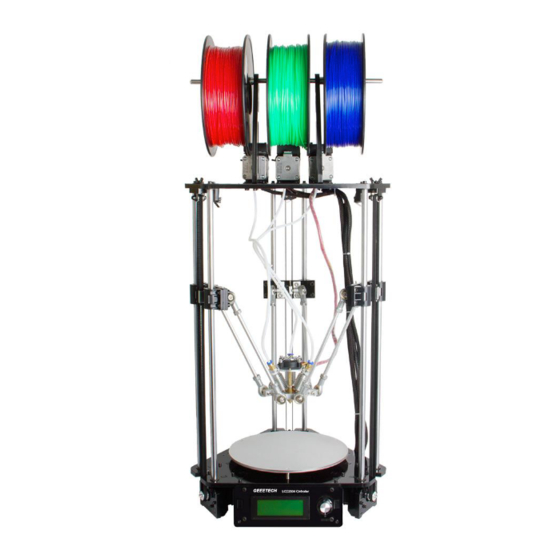
- Page 81 ShenZhen GETECH CO.,LTD www.geeetech.com The Rostock 301 has been fully assembled. Page...
-
Page 82: Tips
ShenZhen GETECH CO.,LTD www.geeetech.com 15 Tips Before printing your first project, it is critical that you correctly calibrate the printer. Skipping or rushing this step will result in frustration and failed prints later, so it is important to take the time to make sure your printer is correctly set up.
Need help?
Do you have a question about the Rostock 301 and is the answer not in the manual?
Questions and answers