Sign In
Upload
Manuals
Brands
YASKAWA Manuals
Control Unit
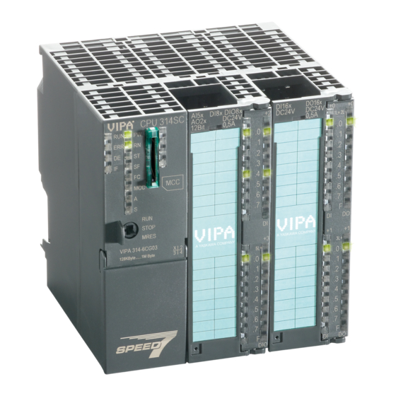
SPEED7 CPU-SC 313-5BF23
YASKAWA SPEED7 CPU-SC 313-5BF23 Manuals
Manuals and User Guides for YASKAWA SPEED7 CPU-SC 313-5BF23. We have
2
YASKAWA SPEED7 CPU-SC 313-5BF23 manuals available for free PDF download: Manual
YASKAWA SPEED7 CPU-SC 313-5BF23 Manual (244 pages)
Brand:
YASKAWA
| Category:
Control Unit
| Size: 9 MB
Table of Contents
Table of Contents
3
1 General
6
Copyright © VIPA Gmbh
6
About this Manual
7
Safety Information
8
2 Basics
9
Safety Information for Users
9
Operating Structure of a CPU
10
General
10
Applications
10
Operands
10
Cpu 313-5Bf23
12
Basic Differences to the Siemens CPU 313C
13
General Data
16
3 Assembly and Installation Guidelines
18
Installation Dimensions
18
Assembly Standard Bus
19
Cabling
21
Installation Guidelines
23
4 Hardware Description
25
Properties
25
Structure
26
General
26
Interfaces
26
In-/Output Area CPU 313-5BF23
28
Memory Management
34
Slot for Storage Media
34
Battery Backup for Clock and RAM
35
Operating Mode Switch
35
Leds
36
Technical Data
38
5 Deployment CPU 313-5BF23
49
Assembly
49
Start-Up Behavior
49
Addressing
50
Overview
50
Addressing Backplane Bus I/O Devices
50
Address Assignment
52
Hardware Configuration - CPU
53
Hardware Configuration - I/O Modules
53
Hardware Configuration - Ethernet PG/OP Channel
54
CPU Parametrization
55
Parametrization Via Siemens CPU
55
CPU Parameters
56
Project Transfer
58
Transfer Via MPI
58
Transfer Via Ethernet
59
Transfer Via Memory Card
60
Accessing the Web Server
61
Operating Modes
68
Overview
68
Function Security
70
Overall Reset
71
Firmware Update
72
Reset to Factory Settings
75
Deployment Storage Media - MMC, MCC
76
Extended Know-How Protection
78
CMD - Auto Commands
79
Diagnostic Entries
80
Control and Monitoring of Variables with Test Functions
81
6 Deployment I/O Periphery
83
Overview
83
In-/Output Area CPU 313-5BF23
84
Address Assignment
91
Analog Part
92
Access to the I/O Part
93
Analog Value Representation
95
Analog Part - Wiring
98
Analog Part - Measurement Principle
99
Analog Part - Parameterization
100
Digital Part
101
Access to the I/O Part
105
Digital Part - Parameterization
106
Counter
107
Counter - Fast Introduction
107
SFB 47 - COUNT - Counter Controlling
111
Counter - Functions
116
Counter - Additional Functions
121
Frequency Measurement
128
Overview
128
Inputs for the Frequency Measurement
128
Parameterization
130
SFB 48 - FREQUENC - Frequency Measurement
131
Pulse Width Modulation - PWM
134
Overview
134
Parameterization
136
SFB 49 - PULSE - Pulse Width Modulation
138
Diagnostic and Interrupt
146
Process Interrupt
146
Diagnostic Interrupt
148
7 Deployment Ptp Communication
155
Fast Introduction
155
Principle of the Data Transfer
156
Deployment of RS485 Interface for Ptp
157
Parametrization
158
FC/SFC 216 - SER_CFG - Parametrization Ptp
158
Communication
158
FC/SFC 217 - SER_SND - Send to Ptp
158
FC/SFC 218 - SER_RCV - Receive from Ptp
159
Protocols and Procedures
159
Modbus - Function Codes
163
Modbus - Example Communication
167
8 Winplc7
169
System Conception
169
Installation
169
Example Project Engineering
170
Job Definition
170
Project Engineering
171
Test the PLC Program in the Simulator
177
Transfer PLC Program to CPU and Its Execution
178
9 Configuration with TIA Portal
180
TIA Portal - Work Environment
180
General
180
Work Environment of the TIA Portal
181
TIA Portal - Hardware Configuration - CPU
181
TIA Portal - Hardware Configuration - I/O Modules
183
TIA Portal - Hardware Configuration - Ethernet PG/OP Channel
184
TIA Portal - VIPA-Include Library
187
TIA Portal - Project Transfer
188
Appendix
190
A System Specific Event Ids
192
B Integrated Blocks
240
CSSL Partial List
244
Advertisement
YASKAWA SPEED7 CPU-SC 313-5BF23 Manual (239 pages)
Brand:
YASKAWA
| Category:
Computer Hardware
| Size: 10 MB
Table of Contents
Table of Contents
3
1 General
6
Copyright © VIPA Gmbh
6
About this Manual
7
Safety Information
8
2 Basics
9
Safety Information for Users
9
Operating Structure of a CPU
10
General
10
Applications
10
Operands
10
Cpu 314-6Cf23
12
General Data
14
3 Assembly and Installation Guidelines
16
Overview
16
Installation Dimensions
17
Assembly SPEED-Bus
18
Assembly Standard Bus
21
Cabling
24
Installation Guidelines
26
4 Hardware Description
28
Properties
28
Structure
29
General
29
Interfaces
29
Memory Management
31
Slot for Storage Media
31
Battery Backup for Clock and RAM
31
Operating Mode Switch
32
Leds
32
In-/Output Range CPU 314-6CF23
35
Technical Data
38
5 Deployment CPU 314-6CF23
49
Assembly
49
Start-Up Behavior
49
Addressing
50
Overview
50
Address Assignment I/O Part
53
Hardware Configuration - CPU
54
Switching CPU Type to CPU 318-2AJ00
55
Hardware Configuration - I/O Modules
56
Hardware Configuration - Ethernet PG/OP Channel
56
Hardware Configuration - SPEED-Bus
58
Preconditions
58
Proceeding
59
Setting Standard CPU Parameters
59
Parameterization Via Siemens CPU
59
Parameters CPU
59
Parameters for DP
62
Parameters for MPI/DP
62
Setting VIPA Specific CPU Parameters
63
Proceeding
63
VIPA Specific Parameters
64
Project Transfer
67
Transfer Via MPI/PROFIBUS
67
Transfer Via Ethernet
69
Transfer Via Memory Card
69
Accessing the Web Server
70
Operating Modes
78
Overview
78
Function Security
80
Overall Reset
81
Firmware Update
82
Reset to Factory Settings
84
Deployment Storage Media - MMC, MCC
85
Extended Know-How Protection
87
CMD - Auto Commands
88
Diagnostic Entries
90
Control and Monitoring of Variables with Test Functions
90
6 Deployment I/O Periphery
92
Overview
92
In-/Output Range CPU 314-6CF23
93
Address Assignment I/O Part
95
Analog Part
96
Analog Part - Parametrization
100
Analog Part - Diagnostic Functions
105
Digital Part
108
Counter - Fast Introduction
110
Counter - In-/Output Area
112
Counter - Parametrization
114
Counter - Functions
120
Counter - Additional Functions
125
Counter - Diagnostic and Interrupt
131
Process Interrupt
132
Diagnostic Interrupt
132
7 Deployment Ptp Communication
137
Fast Introduction
137
Principle of the Data Transfer
138
Deployment of RS485 Interface for Ptp
138
Parametrization
141
FC/SFC 216 - SER_CFG - Parametrization Ptp
141
Communication
141
FC/SFC 217 - SER_SND - Send to Ptp
141
FC/SFC 218 - SER_RCV - Receive from Ptp
142
Protocols and Procedures
142
Modbus - Function Codes
146
Modbus - Example Communication
150
8 Deployment PROFIBUS Communication
152
Overview
152
Fast Introduction
152
Hardware Configuration - CPU
153
Switching CPU Type to CPU 318-2AJ00
154
Deployment as PROFIBUS DP Master
155
Deployment as PROFIBUS DP Slave
156
PROFIBUS Installation Guidelines
158
Commissioning and Start-Up Behavior
161
9 Winplc7
162
System Conception
162
Installation
162
Example Project Engineering
163
Job Definition
163
Project Engineering
164
Test the PLC Program in the Simulator
170
Transfer PLC Program to CPU and Its Execution
171
10 Configuration with TIA Portal
173
TIA Portal - Work Environment
173
General
173
Work Environment of the TIA Portal
174
TIA Portal - Hardware Configuration - CPU
175
TIA Portal - Hardware Configuration - I/O Modules
176
TIA Portal - Hardware Configuration - Ethernet PG/OP Channel
177
TIA Portal - Setting VIPA Specific CPU Parameters
179
TIA Portal - VIPA-Include Library
182
TIA Portal - Project Transfer
183
Appendix
185
A System Specific Event Ids
187
B Integrated Blocks
235
CSSL Partial List
239
Advertisement
Related Products
YASKAWA SM-AIO
YASKAWA SVB
YASKAWA SVB-01
YASKAWA CANopen SI-S3/V
YASKAWA MECHATROLINK Sigma 2 Series
YASKAWA SGDV-OCA03A
YASKAWA SGDH Sigma-II Series
YASKAWA SLIO 050-1BB30
YASKAWA SPEED7 300S+ CPU 315PN
YASKAWA SP-V1M
YASKAWA Categories
Controller
DC Drives
Servo Drives
Robotics
Control Unit
More YASKAWA Manuals
Login
Sign In
OR
Sign in with Facebook
Sign in with Google
Upload manual
Upload from disk
Upload from URL