JRC JCY-1900 Instruction Manual
Voyage data recorder
Hide thumbs
Also See for JCY-1900:
- Instruction manual (170 pages) ,
- Service manual (116 pages) ,
- Operation manual (2 pages)

Related Manuals for JRC JCY-1900


Summary of Contents for JRC JCY-1900
- Page 1 JCY - 1900 1900 VOYAGE DATA RECORDER VOYAGE DATA RECORDER Conforming to IMO MSC.333 ( 90 ) INSTRUCTION INSTRUCTION MANUAL MANUAL...
- Page 3 OTICE - Reproduction of all or part of this manual without permission is prohibited. - The contents of this manual are subject to change without notice. Copyright© Japan Radio Co., Ltd. 2014 All rights reserved. 7ZPNA4384C...
- Page 5 Cautions for High Voltage High voltages, ranging from several hundreds to tens of thousands of volts, are used in electronic apparatus, such as radio and radar instruments. These voltages are totally harmless in most operations. However, touching a component inside the unit is very dangerous. (Any person other than authorized service engineers should not maintain, inspect, or adjust the unit.) High voltages on the order of tens of thousands volts are most likely to cause instant deaths from electrical shocks.
- Page 6 Method of First-Aid Treatment Precautions for First-Aid Treatments Whenever a person is struck by an electrical shock, give the patient artificial respiration immediately on the spot, unless it is absolutely necessary to move the patient for safety's sake. Once started, artificial respiration should be continued rhythmically. (1) Refrain from touching the patient carelessly as a result of the accident;...
- Page 7 Treatment to Give When the Patient Has a Pulse Beating but Has Ceased to Breathe * Performing mouth-to-mouth artificial respiration (see Figure 1). (1) Bend the patient's face backward until it is directed to look back. (A pillow may be placed under the neck.) (2) Pull up the lower jaw to open up the airway.
- Page 8 Flow of Cardiopulmonary Resuscitation (CPR) Using the AED (Automated External Defibrillator) A person is collapsing. - Secure the safety of the surronding area. - Prevent secondary disasters. Listen to the appeal of the Responding Check for response. injured or ill person and give - Call while tapping the shoulder.
- Page 9 Procedure for Cardiopulmonary Resuscitation (CPR) Using the AED (Automated External Defibrillator) 1. Check the scene for safety to prevent secondary disasters a) Do not touch the injured or ill person in panic when an accident has occurred. (Doing so may cause electric shock to the first-aiders.) b) Do not panic and be sure to turn off the power.
- Page 10 6. Check for breathing a) After opening the airway, check quickly for breathing for no more than 10 seconds. Put your cheek down by the mouth and nose area of the injured or ill person, look at his/her chest and abdomen, and check the following three points.
- Page 11 8. Cardiopulmonary resuscitation (CPR) (combination of chest compressions and rescue breaths) a) Position of chest compressions Position the heel of one hand in the center of the chest, approximately between the nipples, and place your other hand on top of the one that is in position. b) Perform chest compressions - Perform uninterrupted chest compressions of 30 at the rate of about 100 times per minute.
- Page 12 9. When to stop cardiopulmonary resuscitation (CPR) a) When the injured or ill person has been handed over to the emergency services. b) When the injured or ill person has started moaning or breathing normally, lay him/her on his/her side in a recovery position and wait for the arrival of emergency services.
- Page 13 12. Electrocardiogram analysis a) The AED automatically analyzes electrocardiograms. Follow the voice prompts of the AED and ensure that nobody is touching the injured or ill person while you are operating the AED. b) On some AED models, you may need to push a button to analyze the heart rhythm.
- Page 14 (Blank page)
-
Page 15: Preface
Preface Preface Thank you for purchasing the JRC JCY-1900 Voyage Data Recorder (VDR). This equipment records the navigation data and the hull data of the vessel, as required by international standards. If a maritime accident occurred, this equipment helps investigators to investigate the cause and prevent the recurrence in the future. - Page 16 Preface (Blank page)
-
Page 17: Before Operation
Before Operation Before Operation Pictorial indication Various pictorial indications are included in this manual and are shown on this equipment so that you can operate them safely and correctly and prevent any danger to you and / or to other persons and any damage to your property during operation. - Page 18 Before Operation (Blank page)
-
Page 19: Precautions
Precautions Precautions DANGER The prohibited matter of a battery and a lithium battery. - To short-circuit the + pin and - pin - Using for non-specified applications - Disassembling, modifying, destroying - Throwing into fire, heating - Using expired battery There is a danger that causes leakage of fluid, generation of heat, fire, explosion, destruction, or injury by heat. - Page 20 Precautions WARNING If equipment malfunctions, make sure to turn off the main power, open the circuit breaker, and please contact our head office, or a nearby branch or local office to request servicing. The continuous use of the equipment may cause a fire or electric shock. The recording control unit (NDV-1900) has a built-in battery.
- Page 21 Precautions WARNING The recording control unit (NDV-1900) has the power socket. When you connect the power plug to the power socket, insert it firmly. Failure to do so may cause fire, burns or electric shock. The recording control unit (NDV-1900) has the power socket. Clean dust from the power plug.
- Page 22 Precautions CAUTION This equipment has warning labels. Do not try to remove, break or modify the label. Do not install the equipment on the location where infringed by water, humidity, steam, dust, or soot. Otherwise, it may cause a fire, electric shock, or malfunction. Do not touch this equipment, if hands or gloves are wet with water.
- Page 23 Precautions CAUTION Do not block up the air vent of this equipment. Otherwise, the inside of equipment is filled with heat, and it may cause fire or malfunction. Do not install the equipment on the unstable place such as on the shaky stand or inclined surface.
- Page 24 Precautions (Blank page)
-
Page 25: Operation Guide When A Maritime Accident Occurred
Operation Guide When a Maritime Accident Occurred Operation Guide When a Maritime Accident Occurred - If a maritime accident occurred, preserve the recorded data in the VDR until the time of accident. - The fixed protective capsule unit or the float-free capsule unit store 48 hours data. The internal storage of RCU store 720 hours data. - Page 26 Operation Guide When a Maritime Accident Occurred 1. Preserving the recorded data So that the VDR does not overwrite the recorded data, preserve the recorded data in the internal storage of RCU. 1) Tap the [Save] button in the HOME screen. 2) Tap the [PROTECT] button in the “Save the recorded data at a marine accident case”...
- Page 27 Operation Guide When a Maritime Accident Occurred 2. Stopping the data recording Stop the recording of data in the fixed protective capsule unit, float-free capsule unit, and internal storage of the RCU. 1) Tap the [Save] button in the HOME screen. 2) Tap the [RECORD STOP/START] button in the “Save the recorded data at a marine accident case”...
- Page 28 Operation Guide When a Maritime Accident Occurred (Blank page) xxiv...
-
Page 29: Exterior Of System Components
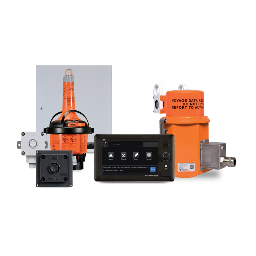
Exterior of System Components Exterior of System Components Recording Control Unit (RCU) Operation Panel Unit (OPU) Fixed Protective Capsule unit (FPC) Float-free Capsule unit (FFC) - Page 30 Exterior of System Components Microphone Waterproof microphone Junction box xxvi...
-
Page 31: Table Of Contents
Contents Contents Preface ............................xi Before Operation ........................xiii Precautions ..........................xv Operation Guide When a Maritime Accident Occurred .............. xxi Exterior of System Components ....................xxv Contents ..........................xxvii Abbreviations and Terms ......................xxxi Chapter 1 Outline of the Equipment ..................1 Functions ........................ -
Page 32: Contents
Contents System Setup - [Setup] Button ..................54 4.6.1 The SYSTEM SETUP screen ................54 4.6.2 Adjusting the screen brightness ................55 4.6.3 Adjusting the volume of screen touch sound ............56 4.6.4 Checking the replacement parts ................58 4.6.5 Checking the system information ................ - Page 33 Contents NWP-69 Frame Grabber Unit ................... 117 8.10 NCT-84 Data Acquisition Unit ................... 118 8.11 NQE-7700A Junction Box ..................119 8.12 General Environmental Condition ................120 Chapter 9 Outside Drawings ....................123 NDH-338 Fixed Protective Capsule Unit ..............123 NDH-339 Float-free Capsule Unit ................
- Page 34 Contents (Blank page)
-
Page 35: Abbreviations And Terms
Abbreviations and Terms Abbreviations and Terms Abbreviations Automatic Identification System Audio Recording Board COSPAS COsmicheskaya Sistyema Poiska Avariynich Sudov (Space System for the Search of Vessels in Distress) Data Acquisition Board Data Acquisition Unit Digital Signal Converter ECDIS Electronic Chart Display and Information System EPIRB Emergency Position Indicating Radio Beacon Float-free Capsule unit... - Page 36 Abbreviations and Terms Terms A.861 IMO Performance Standard for VDR Heading true sentence header ID of IEC61162-1 IEC60945 General Requirements IEC61162 Maritime navigation and radiocommunication equipment and systems - Digital interfaces - IEC61162-1 Part 1: Single talker and multiple listeners IEC61162-2 Part 2: Single talker and multiple listeners, high-speed transmission IEC61162-450...
-
Page 37: Chapter 1 Outline Of The Equipment
Features - Fully compliant with the latest international standards The JCY-1900 is fully compliant with the latest international standards for VDR such as IMO MSC.333(90) and IEC61996-1 Ed.2 that have recently been revised. - Collection of the recorded data via the IP network. -
Page 38: Configuration
Chapter 1 Outline of the Equipment Configuration Table 1-1 shows the standard configuration list of this equipment. Table 1-1 Standard configuration list Component Name Type Name Function Recording Control Unit NDV-1900 - Output the recorded data to the (RCU) fixed protective capsule unit, the float-free capsule unit Main Control Board CDJ-2510... - Page 39 Chapter 1 Outline of the Equipment Table 1-1 Standard configuration list (continued) Component Name Type Name Function Microphone unit NVT-181 - Recording the conversation in the bridge Accessories Spare parts for RCU H-7ZXNA4015 - Cooling fan and fuse for NDV-1900 Table 1-2 lists optional units for the VDR.
-
Page 40: System Diagram
Chapter 1 Outline of the Equipment System Diagram Figure 1-1 Example of system diagram... -
Page 41: Chapter 2 Names And Functions
Chapter 2 Names and Functions Chapter 2 Names and Functions The following describes the name and function of each part of the VDR. NDV-1900 Recording Control Unit 1) Key Figure 2-1 Recording Control Unit (when the front door is closed) 4) Cooling fan b) Audio Recording a) Main Control... - Page 42 Chapter 2 Names and Functions Table 2-1 Name and function of each part of the RCU Name Description The key for the front door. DATA port The accident investigator uses to retrieve the recorded data from the VDR. Battery The battery becomes the backup power supply when an AC input power is lost.
-
Page 43: Ncg-1900 Operation Panel Unit
Chapter 2 Names and Functions NCG-1900 Operation Panel Unit 1) Touch panel 2) Speaker 3) Rotary knob 4) HOME button 5) USB port Figure 2-3 Name of each part of the Operation Panel Unit (OPU) Table 2-3 Name and function of each part of the OPU Name Function Touch panel... - Page 44 Chapter 2 Names and Functions (Blank page)
-
Page 45: Chapter 3 Starting And Stopping The System
Chapter 3 Starting and Stopping the System Chapter 3 Starting and Stopping the System Starting the System 1. Start the Recording Control Unit (RCU) 1) Unlock and open the front door. 2) Turn on the POWER switch. 3) After approximately 2 minutes, make sure that the MCB's LED (SYS., REC.) lights up in green. - Page 46 Chapter 3 Starting and Stopping the System 4) The OPU starts up and displays the startup screen to show in Figure 3-2. Figure 3-2 Startup screen 5) Close and lock the front door. [Information] If the RCU's POWER switch turns on, the following units automatically turn on. - Operation Panel Unit (OPU) - Fixed Protective Capsule unit (FPC) - Float-free Capsule unit (FFC)
- Page 47 Chapter 3 Starting and Stopping the System 2) Turn on the POWER switch. NCT-82 NCT-83 Figure 3-4 The power switch position of the DSC 3. Data Acquisition Unit (DAU) - Option 1) Remove the four setscrews from the front cover. Figure 3-5 The screw position of the DAU...
- Page 48 Chapter 3 Starting and Stopping the System 2) Turn on the POWER switch. Figure 3-6 The power switch position of the DAU 4. Frame Grabber Unit (FGU) - Option 1) Turn on the POWER switch of the front panel. Figure 3-7 The power switch position of the FGU...
- Page 49 Chapter 3 Starting and Stopping the System 5. Check the VDR system starts up normally on the OPU screen. If the VDR system starts up normally, the OPU displays the HOME screen. Figure 3-8 HOME screen If alerts have occurred, clear it by following the procedure described in “4.3 Checking the Alert”. [Information] If the optional DAU is added, an alert occurs in the start-up because the VDR system is not setting the initial heading angle data.
-
Page 50: Stopping The System
Chapter 3 Starting and Stopping the System Stopping the System [NOTE] Do not turn off the circuit breaker of the power distribution board when the RCU is in operation. Otherwise, the uninterruptible power supply is activated and the VDR system operates in the battery. - Page 51 Chapter 3 Starting and Stopping the System 2. Digital Signal Converter (DSC) - Option 1) Remove the four setscrews from the front cover. NCT-82 NCT-83 Figure 3-9 The screw position of the DSC 2) Turn off the POWER switch. NCT-82 NCT-83 Figure 3-10 The power switch position of the DSC...
- Page 52 Chapter 3 Starting and Stopping the System 3. Data Acquisition Unit (DAU) - Option 1) Remove the four setscrews from the front cover. Figure 3-11 The screw position of the DAU 2) Turn off the POWER switch. Figure 3-12 The power switch position of the DAU...
- Page 53 Chapter 3 Starting and Stopping the System 4. Frame Grabber Unit (FGU) 1) Turn off the POWER switch of the front panel. Figure 3-13 The power switch position of the FGU [Information] The POWER switch of following optional units always can keep ON. After the RCU turned off, the following optional units can turn off with the circuit breaker.
- Page 54 Chapter 3 Starting and Stopping the System (Blank page)
-
Page 55: Chapter 4 Operation Method
Chapter 4 Operation Method Chapter 4 Operation Method The operation of the VDR system performs by the OPU. But turning on and turning off the power switch is excluded. CAUTION Do not carry out the tap of the screen by the sharp object. Otherwise, the screen may be damaged. -
Page 56: Screen Transition List
Chapter 4 Operation Method 4.1.2 Screen transition list The screen transition list is displayed to the top of each function screen. Looking at the screen transition list, the current screen can check what is displaying. Figure 4-3 shows [Home] - [Check] - [Image] - [Data check]. -
Page 57: Screen Scrolling
Chapter 4 Operation Method 4.1.3 Screen scrolling If the screen scrollable, the [▲] button, [▼] button, and the display position indicator are displayed. Tapping the [▲] button, the list scrolls up. Tapping the [▼] button, the list scrolls down. The display position indicator shows an approximate position of the selected item on the entire item list. -
Page 58: Number Input
Chapter 4 Operation Method 4.1.5 Number input The number input conducts by the on-screen numeric keypad. The input numbers and the period are displayed to the number input box. But the password is displayed with “●”. Numeric input box Numeric keypad Figure 4-7 Number input Table 4-1 Numeric keypad functions Button... -
Page 59: Home Screen
Chapter 4 Operation Method HOME Screen The HOME screen is the VDR's main screen. The VDR system displays each function screen from the HOME screen. [Information] If nothing is operated for 10 minutes, it returns to the HOME screen automatically. However, if the ALERT CHECK screen is displayed, it doesn't return to the HOME screen. - Page 60 Chapter 4 Operation Method Table 4-2 Function button Button Function Description Checking the Displays the ALERT screen. Takes actions to the alert. alert See “4.3 Checking the Alert”. Alert Checking the Displays the DATA CHECK screen. Checks the recorded data connected units to the VDR system.
- Page 61 Chapter 4 Operation Method ALERT screen HOME screen DATA CHECK screen DATA COPY screen SETUP screen (Option) GYRO I/F screen Figure 4-9 Screen transition from the HOME screen...
- Page 62 Chapter 4 Operation Method 4. Accident countermeasure guidance If a maritime accident occurred, tap the [Save] button to protect the recorded data. See “4.8 Actions to Take in the Event of an Accident”. HOME screen Save the recorded data at a marine accident case Figure 4-10 Save the recorded data at a marine accident case...
-
Page 63: Checking The Alert - [Alert] Button
Chapter 4 Operation Method Checking the Alert - [Alert] Button The currently occurring alert can check on the HOME screen and the ALERT screen. If the expiration date of the replacement parts is under 1 year, the INFORMATION alert is displayed in the ALERT CHECK screen. -
Page 64: Checking For Alerts
Chapter 4 Operation Method 4.3.2 Checking for alerts If the alert occurs, the alert button and contents of the alert are displayed on the HOME screen. - Alert display - Alert contents display Alert contents display Alert button Alert display (When the alert occurred) WARNING button CAUTION button... - Page 65 Chapter 4 Operation Method The dialog box of alert contents is displayed in the following case: - If new alert occurs. - If the alert button taps. If new alert occurs, the dialog box of alert contents is displayed automatically. Alert state icon [ACK] button Switching button...
-
Page 66: If New Alert Occurs
Chapter 4 Operation Method 4.3.3 If new alert occurs 1. If new alert occurs, the dialog box of alert contents is displayed automatically. If the WARNING alert occurs, sounds the alert sound with the alert indication. [Information] If the screen that is not the HOME screen is displayed, return to the HOME screen. Then, the dialog box is displayed. -
Page 67: Checking The Contents Of Alert By The Alert Button
Chapter 4 Operation Method [Information] If the multiple WARNING alerts occur, the next WARNING alert is displayed automatically. 3. Solve the cause of the alert. See “6.3 Troubleshooting” and solve the cause of the alert. If the cause of the alert solves. Closes the dialog box of alert contents. - Page 68 Chapter 4 Operation Method 3. Check the contents of alert. - If the WARNING alert occurs: Check the contents of alert and taps the [ACK] button. Tapping the [ACK] button, the alert sound disappears. If so the [ACK] button is disabled and the alert state icon changes from Before acknowledgement of the alert contents [ACK] button: enable →...
-
Page 69: Displaying The Alert List Display
Chapter 4 Operation Method 4.3.5 Displaying the alert list display In the ALERT screen, the list of alert that is occurring now is displayed. The alert is displayed in order of its priority. 1. Tap the ALERT button on the HOME screen. HOME screen ALERT screen Figure 4-18 ALERT screen... - Page 70 Chapter 4 Operation Method 2. Tapping the list item that would like to display, the contents of alert is displayed. ALERT screen Dialog box of alert contents Figure 4-19 Alert details display screen...
-
Page 71: Copying The Recorded Data - [Copy] Button
Chapter 4 Operation Method Copying the Recorded Data - [Copy] Button The preserved data by the PROTECT operation and the recorded data in the internal storage can copy to the USB flash drive for up to 6 hours. [Information] The recorded data can't copy to the secure USB flash drives and the USB card reader. 1. - Page 72 Chapter 4 Operation Method 3. Tap the [Select] button in the DATA COPY screen. DATA COPY screen DATA SELECT screen Figure 4-22 DATA SELECT screen 4. Tap the [Select] button in the DATA SELECT screen and select from the drop-down list the recorded data that would like to copy.
- Page 73 Chapter 4 Operation Method 5. If [Latest data] is selected, change the date and time of recorded data that would like to copy by the button shown in Table 4-7. The date and time of recorded data that would like to copy Figure 4-24 Setting the date and time of recorded data In Figure 4-24, selects the recorded data for six hours from 23:00 on April 1, 2014 to 5:00 on April 2, 2014.
- Page 74 Chapter 4 Operation Method 6. Tap the [Set] button in the DATA SELECT screen. Returns to the DATA COPY screen and displays the date and time that would like to copy in the [Period] field. DATA SELECT screen DATA COPY screen Figure 4-25 Deciding date and time of recorded data 7.
- Page 75 Chapter 4 Operation Method 8. Tap the [Copy] button in the DATA COPY screen, then starts copying. If the data starts to be copied, the progress bar is displayed. During copying, the [Copy] button turns into the [Cancel] button. Tapping the [Cancel] button, stops a copy. DATA COPY screen Figure 4-27 Copy operation [Information]...
-
Page 76: Checking The Recorded Data - [Check] Button
Chapter 4 Operation Method Checking the Recorded Data - [Check] Button The recorded data in the VDR system can check in the DATA CHECK screen. Table 4-8 Recorded data that can check Item Description Sensor The sensor data of the GPS, the AIS, the gyro and so on. Image The image data of the radar, and the ECDIS. - Page 77 Chapter 4 Operation Method Table 4-10 indicates the indications in the DATA CHECK screen. Table 4-10 Indication in DATA CHECK screen Indication Color [Status] field [Check] field Normal judgment. All items Green Normal operation judged the [Good]. There is the non-judgment Yellow Abnormal operation item.
-
Page 78: Checking The Sensor Data
Chapter 4 Operation Method 4.5.2 Checking the sensor data 1. Tap the [Sensor] field in the DATA CHECK screen. DATA CHECK screen SENSOR DATA LIST screen Figure 4-29 SENSOR DATA LIST screen Table 4-12 indicates the items in the SENSOR DATA LIST screen. Table 4-12 Item in SENSOR DATA LIST screen Item Description... - Page 79 Chapter 4 Operation Method 2. Tap the equipment field that would like to check. SENSOR DATA LIST screen SENSOR DATA CHECK screen Figure 4-30 SENSOR DATA CHECK screen 3. Check that the sensor data are received normally. [Good] button [Fail] button Displays the presence of the communication within 1 minute [Up] button...
-
Page 80: Checking The Image Data
Chapter 4 Operation Method 4. The [Check] field displays the judgement result. SENSOR DATA LIST screen Figure 4-32 SENSOR judgment result 5. For all registered equipments in the list, conduct from Step 2 to Step 4. 4.5.3 Checking the image data 1. - Page 81 Chapter 4 Operation Method Table 4-14 indicates the items in the IMAGE DATA LIST screen. Table 4-14 Item in IMAGE DATA LIST screen Item Description Equipment The equipment name. The identification code: R*: Radar E*: ECDIS D*: Multi function display Status The status of recorded data.
- Page 82 Chapter 4 Operation Method 3. Check that the image data is received normally. If the image data is received normally, tap the [Good] button. If the image data can't receive, tap the [Fail] button. Tapping the [Good] button or the [Fail] button, returns to the IMAGE DATA LIST screen.
- Page 83 Chapter 4 Operation Method 4. In the ECDIS, check that the chart information is received normally. Tap the [info.] button in the IMAGE DATA CHECK screen. Then the chart information is displayed. Tapping the [Image] button in the CHART INFORMATION CHECK screen, returns to the IMAGE DATA CHECK screen.
-
Page 84: Checking The Audio Data
Chapter 4 Operation Method 4.5.4 Checking the audio data 1. Tap the [Audio] field in the DATA CHECK screen. DATA CHECK screen AUDIO DATA LIST screen Figure 4-38 AUDIO DATA LIST screen Table 4-16 indicates the items in the AUDIO DATA LIST screen. Table 4-16 Item in AUDIO DATA LIST screen Item Description... - Page 85 Chapter 4 Operation Method 2. Tap the equipment that would like to check. AUDIO DATA LIST screen AUDIO DATA CHECK screen Figure 4-39 AUDIO DATA CHECK screen...
- Page 86 Chapter 4 Operation Method 3. Records the conversation of the bridge, the wings, and the VHF radio communication. Then, plays back those audio data. 1) Tap the [REC] button. Then the recording starts. During the recording, the recording time is displayed with the display of “Recording”. If the recording time passes 1 minute, the recording stops automatically.
-
Page 87: Checking The Recording Time
Chapter 4 Operation Method 4. Conducts the self-diagnosis test of the microphone. [Information] The self-diagnosis test is function only for the microphone. 1) Tap the [Test] button in the AUDIO DATA CHECK screen. Then the self-diagnosis test starts. 2) After approximately 1 minute, the result of self-diagnosis test is displayed to the right side of the [Test] button, and the indication of the [Status] field changes. -
Page 88: Saving The Judgment Results
Chapter 4 Operation Method 2. Check the recording period of the FPC, the FFC, and the internal storage. Table 4-20 Indication in MEDIUM screen Indication Color Description The Data for the specified length of time or more has been Green recorded. -
Page 89: Displaying The Data Check History
Chapter 4 Operation Method 4.5.7 Displaying the data check history 1. Tap the [History] in the DATA CHECK screen. DATA CHECK screen DATA CHECK HISTORY screen Figure 4-43 DATA CHECK HISTORY screen Table 4-21 Indication in DATA CHECK HISTORY screen Indication Color Description... -
Page 90: System Setup - [Setup] Button
Chapter 4 Operation Method System Setup - [Setup] Button In the SYSTEM SETUP screen, it's possible to change the VDR system settings and check the VDR system information. 4.6.1 The SYSTEM SETUP screen 1. Tapping the [Setup] button, then the SYSTEM SETUP screen is displayed. HOME screen SYSTEM SETUP screen Figure 4-44 SYSTEM SETUP screen... -
Page 91: Adjusting The Screen Brightness
Chapter 4 Operation Method 4.6.2 Adjusting the screen brightness 1. Tap the [Setup] button. The SYSTEM SETUP screen is displayed. HOME screen SYSTEM SETUP screen Figure 4-45 SYSTEM SETUP screen 2. Tap the [Dimmer]. The BRIGHTNESS ADJUSTMENT screen is displayed. SYSTEM SETTING screen BRIGHTNESS ADJUSTMENT screen Figure 4-46 BRIGHTNESS ADJUSTMENT screen... -
Page 92: Adjusting The Volume Of Screen Touch Sound
Chapter 4 Operation Method 3. Adjust the screen brightness by operating the buttons listed in Table 4-23. Table 4-23 Brightness adjustment button Button Function Turns down the screen brightness. Turns up the screen brightness. Indicates the current screen brightness. The range of screen brightness adjustment is “0” to “30”. “0” is a minimum brightness and “30”... - Page 93 Chapter 4 Operation Method 2. Tap the [Volume]. The VOLUME ADJUSTMENT screen is displayed. SYSTEM SETUP screen VOLUME ADJUSTMENT screen Figure 4-48 VOLUME ADJUSTMENT screen 3. Adjust the volume by operating the button listed in Table 4-24. Table 4-24 Volume adjustment button Button Function Turns down the volume of screen touch sound.
-
Page 94: Checking The Replacement Parts
Chapter 4 Operation Method 4.6.4 Checking the replacement parts 1. Tap the [Setup] button. The SYSTEM SETUP screen is displayed. HOME screen SYSTEM SETUP screen Figure 4-49 SYSTEM SETUP screen... - Page 95 Chapter 4 Operation Method 2. Tap the [Replacement parts]. In the REPLACEMENT PARTS screen, it's possible to check the following items: - The expiration date of the FPC underwater acoustic beacon - The expiration date of the FFC built-in battery - The expiration date of the FFC Hydrostatic Release Unit (HRU) - The expiration date of the RCU built-in battery - The expiration date of the RCU built-in fan...
-
Page 96: Checking The System Information
Chapter 4 Operation Method 4.6.5 Checking the system information 1. Tap the [Setup] button. The SYSTEM SETUP screen is displayed. HOME screen SYSTEM SETUP screen Figure 4-51 SYSTEM SETUP screen 2. Tap the [System information]. In the SYSTEM INFORMATION screen, it's possible to check the software version of the VDR system. -
Page 97: Changing The Password
Chapter 4 Operation Method 4.6.6 Changing the password 1. Tap the [Setup] button. The SYSTEM SETUP screen is displayed. HOME screen SYSTEM SETUP screen Figure 4-53 SYSTEM SETUP screen 2. Tap the [Change password]. The CHANGE PASSWORD screen is displayed. SYSTEM SETUP screen CHANGE PASSWORD screen Figure 4-54 CHANGE PASSWORD screen... - Page 98 Chapter 4 Operation Method 3. Enter the current password in the [Current Password] field. [Information] The factory default password is “0000”. Manage the password by the ship administrator. About how to enter a number, see “4.1.5 Number input”. 4. After tap the [Enter] button, the cursor moves to the [New password] field. 5.
-
Page 99: Initial Setting Of The Heading Angle - [Gyro I/F] Button
Chapter 4 Operation Method Initial Setting of the Heading Angle - [Gyro I/F] Button If the ship's heading angle data input the synchronous or step signals and the ship's speed data input the pulse signals, the DAU is required. The gyro interface board is optional. [NOTE] If the DAU is added, the CAUTION alert occurs until set the ship's heading angle. - Page 100 Chapter 4 Operation Method 2. Check the ship's heading angle that the gyro compass displays. Then enter the read value in the [Gyro setting] input box. [Information] About how to enter a number, see “4.1.5 Number input”. Enter the read value of gyro compass.
-
Page 101: Actions To Take In The Event Of An Accident - [Save] Button
Chapter 4 Operation Method Actions to Take in the Event of an Accident - [Save] Button If a maritime accident occurred, it is mandatory to preserve the recorded data by the VDR until the time of accident. This section explains guideline for preserving the recorded data. In the event of an accident, check the situation, and preserve the recorded data immediately. -
Page 102: Actions To Take At The Occurrence Of Accident
Chapter 4 Operation Method 4.8.1 Actions to take at the occurrence of accident If a maritime accident occurred, tap the [Save] button and display the “Save the recorded data at a marine accident case”. HOME screen Save the recorded data at a marine accident case Preserving the recorded data when an Stopping and restarting the recording accident occurred... -
Page 103: Preserving The Recorded Data At The Occurrence Of Accident
Chapter 4 Operation Method 4.8.2 Preserving the recorded data at the occurrence of accident 1. Tap the [Save] button in the HOME screen. The “Save the recorded data at a marine accident case” screen is displayed. HOME screen Save the recorded data at a marine accident case Figure 4-59 Save the recorded data at a marine accident case 2. - Page 104 Chapter 4 Operation Method 3. Set the date and time when the accident occurred. Using four buttons shown in Table 4-25, set the cursor center to the date and time when the accident occurred. As center on the cursor, the recorded data is preserved from three hours before to three hours after.
- Page 105 Chapter 4 Operation Method 4. Tapping the [Select] button, then the drop-down list is displayed. Select the destination save area to save the preserved data. [Information] The number of the save area is up to 3. If the save area has no space, see “4.8.3 Releasing the preserved data” and release the unnecessary preserved data.
-
Page 106: Releasing The Preserved Data
Chapter 4 Operation Method 4.8.3 Releasing the preserved data [NOTE] It's recommended to secure the space of preserved data in order to preserve the recorded data immediately. 1. Tap the [Save] button in the HOME screen. The “Save the recorded data at a marine accident case”... - Page 107 Chapter 4 Operation Method 2. Tap the [PROTECT] button. The DATA PROTECT screen is displayed. Save the recorded data at a marine accident case DATA PROTECT screen Figure 4-65 DATA PROTECT screen 3. Tapping the [Select] button, then the drop-down list is displayed. Select the preserved data to release from the drop-down list.
- Page 108 Chapter 4 Operation Method 4. Tapping the [Release] button, then the PASSWORD INPUT screen is displayed. DATA PROTECT screen PASSWORD INPUT screen Figure 4-67 [Release] button 5. Enter the password and tap the [Enter] button. The preserved data is released, and the successful completion message is displayed.
-
Page 109: Stopping The Recording Or Restarting The Recording
Chapter 4 Operation Method [Information] If the password is incorrect, the error message is displayed. Enter the password again. Error message Figure 4-69 Incorrect password error 4.8.4 Stopping the recording or restarting the recording Stops or restarts the data recording in the FPC, the FFC, and the RCU internal storage. [NOTE] - Follow the directions of the relevant authorities as to whether to stop or restart the data recording. - Page 110 Chapter 4 Operation Method 2. Tap the [RECORD STOP/START] button. The RECORD STOP screen is displayed. Save the recorded data at a marine accident case RECORD STOP screen Figure 4-71 RECORD STOP screen...
- Page 111 Chapter 4 Operation Method 3. Enter the password and tap the [Enter] button. Data recording is stopped, and the successful completion message is displayed. [Information] The factory default password is “0000”. Manage the password by the ship administrator. About how to enter a number, see “4.1.5 Number input”. Completion message Figure 4-72 Stop data recording [NOTE]...
- Page 112 Chapter 4 Operation Method 4. During the recording is stopping, tap the [RECORD STOP/START] button in the “Save the recorded data at a marine accident case” screen. The RECORD START screen is displayed. Save the recorded data at a marine accident case RECORD START screen Figure 4-75 RECORD START screen 5.
-
Page 113: Operations Using The Rotary Knob
Chapter 4 Operation Method Operations Using the Rotary Knob Explains the on-screen operations by using the rotary knob. If the touch panel breaks down and can't be operated, uses the rotary knob. 1. Hold down the rotary knob for 5 seconds. If the rotary knob is held down for 5 seconds, the function of rotary knob changes from the “Dimmer mode”... - Page 114 Chapter 4 Operation Method (Blank page)
-
Page 115: Chapter 5 About Float-Free Capsule
- The EPIRB function of the float-free capsule is a function for searching for the capsule in which the VDR recorded date at the time of an accident, and is not an object for lifesaving. JRC cannot accept responsibility for any loss due to incorrect operation, malfunction and other causes except product guarantee condition and liability by law. - Page 116 Chapter 5 About Float-free Capsule WARNING If the false distress alert is transmitted, take the following instructions immediately. (1) Stop the transmission immediately. (2) Report the following information to the Maritime Safety Agency. (a) Ship's name, type and flag (b) Capsule ID number (15 character UIN) (c) Position and time at the false transmission (d) Cause of the false transmission (e) Type, serial number and delivery date of the capsule...
- Page 117 ID are wrong. If the ship's name and ID indicated on the label of the capsule unit is wrong, ask the purchasing dealer, JRC agent or the JRC branches to change it with correct ship's name and ID.
- Page 118 Do not make the used battery to short-circuit, discharging electricity compulsorily or using for other usages. Send used batteries to the purchasing dealer, JRC agent or JRC branches. Do not discard used batteries. Send used batteries to the purchasing dealer, JRC agent or JRC branches, to avoid causing environmental problem by throwing them away.
- Page 119 If the abnormal status is recognized in the capsule. request the service to purchasing dealer, JRC agent or JRC branches, If you want to replace or repair the capsule, contact the purchasing dealer, JRC agent or JRC branches. Do not use a solvent (paint-thinner, alcohol etc.) or alkaline/neutral detergent to clean up the capsule.
-
Page 120: Epirb Transmission Status
Chapter 5 About Float-free Capsule EPIRB Transmission Status In the Float-free Capsule (FFC), transmission status of the EPIRB function is determined based on the following state. - Control switch position - Immersed condition (immersed in water, or not) - Detachable condition (mounted on the bracket, or released) Table 5-1 shows the EPIRB transmission status in each case. -
Page 121: Manual Operating And Activation
Chapter 5 About Float-free Capsule Manual Operating and Activation It is not recommended to operate the EPIRB function inside a life raft or under a cover or canopy. Do not tie the lanyard (mooring rope) to the ship in distress, as this will prevent the unit to functioning if the ship sinks. -
Page 122: Epirb Function Testing
Chapter 5 About Float-free Capsule EPIRB Function Testing As a periodical inspection, please perform every month. There are two different kinds of tests: 1. NORMAL SELF-TEST 2. EXTENDED SELF-TEST including the GPS-test [NOTE] - Perform the periodic inspection, while anchoring in a port. - What the EXTENDED SELF-TEST actually does is to send out a short test signal on 121.5 and 406.037MHz, testing the output of the transmitter. - Page 123 Chapter 5 About Float-free Capsule 3. The test results judge by the LED that is the top of storage module. If the LED blinks only once, the test is pass. Table 5-2 Error message by LED blinking Number of flashing Fault indication None Low power on 406MHz transmitter...
-
Page 124: Extended Self-Test Including Gps-Test
Chapter 5 About Float-free Capsule 5.3.2 EXTENDED SELF-TEST including GPS-test 1. Release front cover by removing the cotter pin. The cotter pin 2. Move switch to “TEST” position twice within 3 seconds and release back to “READY” position. 3. A short beep sounds, and the test starts. During the test, until the capsule acquires the GPS position, a short beep sounds every three seconds. -
Page 125: Visual Inspection
Chapter 5 About Float-free Capsule 5.3.3 Visual inspection As the visual inspection, please check the followings: 1. When the capsule release away, checks that there is no obstacle in the circumference of the bracket. 2. Check for defects on the capsule and the bracket. 3. - Page 126 Chapter 5 About Float-free Capsule (Blank page)
-
Page 127: Chapter 6 Maintenance And Inspection
Chapter 6 Maintenance and Inspection Chapter 6 Maintenance and Inspection WARNING Do not attempt inspections or repairs on the internal part of the equipment by yourself. Inspections or repairs by anyone other than qualified maintainers may cause a fire or electric shock. Please contact our head office, or a nearby branch or local office to request servicing. -
Page 128: Checking The Expiration Date Of Battery
Chapter 6 Maintenance and Inspection 6.1.2 Checking the expiration date of battery Check the expiration date of the RCU built-in battery, the underwater acoustic beacon of the fixed protective capsule unit and the float-free capsule unit built-in battery. If the expiration date is approaching, please contact our head office, or a nearby branch or local office to request servicing. -
Page 129: Troubleshooting
Chapter 6 Maintenance and Inspection Troubleshooting If the VDR malfunctions, troubleshoot it according to the following list. Read the cause and take the actions recommended on the list. If the malfunction persists or there is a problem not listed below, contact the Sales Department, the nearest branch company, branch office, sales office, or any agent of Japan Radio Co., Ltd. - Page 130 Chapter 6 Maintenance and Inspection Trouble symptom Cause Actions to take The LCD screen became dark. The OPU's screen brightness Adjust the screen brightness is becoming low. by the rotary knob. The life of OPU's LCD is Check the OPU's operating approaching.
- Page 131 Chapter 6 Maintenance and Inspection Error Error Alert indication Alert contents Actions to take code type WARNING VDR operation failure The RCU can't 1) Check the cable. communicate the OPU. 2) Reboot the RCU. WARNING Recording stop The data recording is When the data recording stopped to stopping.
- Page 132 Chapter 6 Maintenance and Inspection Error Error Alert indication Alert contents Actions to take code type CAUTION Time synchronization The RCU can't receive Check the GPS. If the GPS is failure the ZDA sentence from working normally, please contact our the GPS.
- Page 133 Chapter 6 Maintenance and Inspection Error Error Alert indication Alert contents Actions to take code type CAUTION Fixed capsule The FPC can't record Reboot the RCU. recording failure data. CAUTION Float-free capsule The FFC's data The image size may be too large short store period recording possible time temporarily by radar echo.
- Page 134 Chapter 6 Maintenance and Inspection Error Error Alert indication Alert contents Actions to take code type WARNING ARB internal failure The internal error of the Reboot the RCU and check it works ARB is occurring. normally. If there is still a problem, please contact our head office, or a nearby branch or local office to request servicing.
- Page 135 Chapter 6 Maintenance and Inspection Error Error Alert indication Alert contents Actions to take code type 403 to CAUTION Sensor reception The sensor data can't 1) Check the wiring between the failure (DAU2-CH*) receive from the DAU. RCU and the DAU. *: 1 to 10 2) Check the wiring between the DAU and the sensor.
- Page 136 Chapter 6 Maintenance and Inspection Error Error Alert indication Alert contents Actions to take code type CAUTION Sensor reception The output data of 1) Check the wiring between the failure (DAU4-GYRO) DAU's built-in gyro RCU and the DAU. interface can't receive. 2) Check the DAU.
-
Page 137: Chapter 7 After-Sale Services
Chapter 7 After-sale Services Chapter 7 After-sale Services When Requesting a Repair If you suspect that this equipment fails, read “Chapter 6 Maintenance and Inspection” and take the action recommended thereof. However, if this equipment will still be faulty, please stop using this equipment and contact your sales representative, our sales department, nearest branch office or sales office. - Page 138 If there are unknown items, please contact the ship and fill in as accurately as possible. Company name: Equipment name: Ship name: Model name: JCY-1900 Phone number: Serial number: FAX number: Date of manufacture: Check the following items sequentially and circle either “Yes” or “No” for each item. If neither applies or error code is displayed on the OPU, please write down details in (7).
-
Page 139: About Disposal
Chapter 7 After-sale Services About Disposal 7.2.1 About disposal of these equipment WARNING If disposing of the recording control unit (NDV-1900), be sure to abide by applicable local laws and regulations. If disposing of the float-free capsule unit (NDH-339), please contact our head office, or a nearby branch or local office to request servicing. -
Page 140: About The China Rohs
Chapter 7 After-sale Services 7.2.3 About the China RoHS 有毒有害物质或元素的名称及含量 (Names & Content of Toxic and Hazardous Substances or Elements) : JCY-1900 : Voyage Data Recorder 形式名 (Type) 名称 (Name) 有毒有害物质或元素 (Toxic and Hazardous Substances and Elements) 部件名称 (Part name) 铅... -
Page 141: Chapter 8 Specifications
Chapter 8 Specifications Chapter 8 Specifications NDH-338 Fixed Protective Capsule Unit Performance Interface Standard IEEE802.3 (10Base-T/100Base-TX) Protocol TCP/IP Recording duration and capacity Duration 48 hours Capacity 32GB Data recording interval Sensor data Depends on the input from the sensors (usually 1 second) Audio data Continuous (1 audio file per minute) - Page 142 Chapter 8 Specifications Environmental condition The recording data in the final recording medium shall be held without loss under below the condition. Shock A half sine-wave pulse of 50G, with a duration of 11 msec Penetration A mass of 250kg with a pin of 100mm diameter, dropped from 3m Fire 10 hours with 260°C fire...
-
Page 143: Ndh-339
Chapter 8 Specifications NDH-339 Float-free Capsule Unit Performance Interface Standard IEEE802.3 (10Base-T/100Base-TX) Protocol TCP/IP Recording duration and capacity Duration 48 hours Capacity 64GB Data recording interval Sensor data Depends on the input from the sensors (usually 1 second) Audio data Continuous (1 audio file per minute) Image data 1 image file of each equipment per 15 seconds... - Page 144 Chapter 8 Specifications Environmental condition Degree of protection 10m depth at 5 minutes Operating temperature -20°C to +55°C (IEC61097-2 satellite EPIRB) Storage temperature -30°C to +70°C (IEC61097-2 satellite EPIRB) General specification Input voltage range Power over Ethernet (IEEE802.3af) Power consumption Size 235.8(w) x 214.2(d) x 528.5(h) mm Mass...
-
Page 145: Ndv-1900 Recording Control Unit
Chapter 8 Specifications NDV-1900 Recording Control Unit Performance Interface to the fixed protective capsule unit Standard IEEE802.3 (10Base-T/100Base-TX) Protocol TCP/IP Power supply Supply from the RCU Interface to the float-free capsule unit Standard IEEE802.3 (10Base-T/100Base-TX) Protocol TCP/IP Power supply Supply from the RCU Power over Ethernet (IEEE802.3af) Sensor data input Standard... - Page 146 Chapter 8 Specifications Performance (continued) Image data input Standard IEC61162-450 Input channel Up to 6 channels (image sources on the network) Recording interval 1 image file of each equipment per 15 seconds (X-Band Radar, S-Band Radar, Main-ECDIS and Sub-ECDIS) * Recording image of each equipment is selected automatically Image format PNG format...
- Page 147 Chapter 8 Specifications Environmental condition Operating temperature -15°C to +55°C (IEC60945 protected type) Temperature and humidity +40°C, 93% (non condensing) Vibration 2Hz to 13.2Hz ±1.0mm 13.2Hz to 100Hz 0.7G Protection class IP22 General specification Power voltage AC 100 to 120V ±10%, 1-phase 50/60Hz (IEC60945) AC 200 to 240V ±10%, 1-phase 50/60Hz (IEC60945) Power consumption 230W (In UPS battery charge)
-
Page 148: Ncg-1900 Operation Panel Unit
Chapter 8 Specifications NCG-1900 Operation Panel Unit Performance Mounting Flush mount type Interface to the RCU Standard IEEE802.3 (10Base-T/100Base-TX) Protocol TCP/IP Power supply Supply from the RCU Indication 7 inch wide color LCD (800 x 480 pixels) Speaker Operation Touch panel Rotary knob USB connector A type receptacle (for USB memory) -
Page 149: Microphone Unit
Chapter 8 Specifications NVT-181 Microphone Unit Performance Mounting Ceiling mount type Device Electoret condenser microphone Directivity Hemisphere indirectivity Range of receive Radius of 3.5m Power supply Supply from the RCU Microphone test Built-in speaker for self-diagnosis test Compass safety distance Standard 0.1m Steering... -
Page 150: Waterproof Microphone Unit
Chapter 8 Specifications NVT-182 Waterproof Microphone Unit Performance Mounting Wall mount type Device Electoret condenser microphone Directivity Hemisphere indirectivity Range of receive Radius of 3.5m Power supply Supply from the RCU Microphone test Built-in speaker for self-diagnosis test Compass safety distance Standard 0.1m Steering... -
Page 151: Digital Signal Converter (64Ch)
Chapter 8 Specifications NCT-83 Digital Signal Converter (64CH) Performance Dry contact input Dry contact Dry contact input channel Up to 64 channels Contact closure interface Driving power supply DC +12V Logic Normal Close / Normal Open Communication port Connect to the RCU Output sentence IEC61162-1 Compass safety distance... -
Page 152: Digital Signal Converter (32Ch)
Chapter 8 Specifications NCT-82 Digital Signal Converter (32CH) Performance Dry contact input Dry contact Dry contact input channel Up to 32 channels Contact closure interface Driving power supply DC +12V Logic Normal Close / Normal open Communication port Connect to the RCU Output sentence IEC61162-1 Compass safety distance... -
Page 153: Frame Grabber Unit
Chapter 8 Specifications NWP-69 Frame Grabber Unit Performance Image data input Input channel 2 channels Input interface Analog RGB / Hs / Vs - RGB 0.7Vp-p (video signal) - Hs - Vs Resolution 640 x 350 to 1600 x 1200 pixel (according to VESA DMTS) 1920 x 1200 pixel (according to VESA CVT RB) Refresh rate... -
Page 154: Data Acquisition Unit
Chapter 8 Specifications 8.10 NCT-84 Data Acquisition Unit Performance Input sensor channel IEC61162-1 8 channels IEC61162-2 2 channels Interface to the RCU Standard IEEE802.3 (10Base-T/100Base-TX) Protocol TCP/IP Compass safety distance Standard 0.9m Steering 0.5m Gyro interface Signal input - Synchronized signal for the gyro compass Ratio: 360X / 180X / 90X / 36X Voltage: AC +24 to +115V Frequency: 50 / 60 / 400Hz... -
Page 155: Nqe-7700A Junction Box
Chapter 8 Specifications 8.11 NQE-7700A Junction Box Performance interface Built-in terminal blocks Environmental condition Operating temperature: -25°C to +55°C (IEC60945 protected type) Temperature and humidity: +40°C, 93% (non condensing) Vibration 2Hz to 13.2Hz ±1.0mm 13.2Hz to 100Hz 0.7G Protection class IP56 General specification Size... -
Page 156: General Environmental Condition
Chapter 8 Specifications 8.12 General Environmental Condition Operating condition and location Usage Conditions Target vessels - Mercantile vessels of 3000G/T or more that are engaged in international voyage - Passenger vessels of 150G/T or more that are engaged in international voyage Unit installation locations Fixed protective capsule unit External deck above bridge... - Page 157 Chapter 8 Specifications Environment condition Exposed type equipment Fixed protective capsule unit, waterproof microphone unit Operation temperature range -25°C to +55°C Storage temperature -25°C to +70°C Temperature and humidity +40°C, 93% (non condensing) Vibration 2Hz to 13.2Hz ±1.0mm 13.2Hz to 100Hz 0.7G Protected type equipment Recording control unit, Operation panel unit, microphone unit, option unit Operation temperature range...
- Page 158 Chapter 8 Specifications (Blank page)
-
Page 159: Chapter 9 Outside Drawings
Chapter 9 Outside Drawings Chapter 9 Outside Drawings NDH-338 Fixed Protective Capsule Unit... -
Page 160: Float-Free Capsule Unit
Chapter 9 Outside Drawings NDH-339 Float-free Capsule Unit FLOAT-FREE CAPSULE UNIT NDH-339 MASS: APPROX. 5.2kg COLOR: ORANGE UNIT: mm 2014/2/18... -
Page 161: Ndv-1900 Recording Control Unit
Chapter 9 Outside Drawings NDV-1900 Recording Control Unit UNIT: mm 2013/10/30... -
Page 162: Ncg-1900 Operation Panel Unit
Chapter 9 Outside Drawings NCG-1900 Operation Panel Unit 2013/10/15... -
Page 163: Microphone Unit
Chapter 9 Outside Drawings NVT-181 Microphone Unit 2013/10/17... -
Page 164: Nvt-182
Chapter 9 Outside Drawings NVT-182 Waterproof Microphone Unit 2013/10/17... -
Page 165: Nct-83
Chapter 9 Outside Drawings NCT-83 Digital Signal Converter (64CH) 2013/10/15... -
Page 166: Nct-82
Chapter 9 Outside Drawings NCT-82 Digital Signal Converter (32CH) 2013/10/15... -
Page 167: Nwp-69 Frame Grabber Unit
Chapter 9 Outside Drawings NWP-69 Frame Grabber Unit 2013/10/15 Standard item (there is no waterproof hood) - Page 168 Chapter 9 Outside Drawings 2013/10/15 Option item (there is a waterproof hood)
-
Page 169: Nct-84
Chapter 9 Outside Drawings 9.10 NCT-84 Data Acquisition Unit 2013/10/15... -
Page 170: Nqe-7700A Junction Box
Chapter 9 Outside Drawings 9.11 NQE-7700A Junction Box 2013/11/19... - Page 171 Chapter 9 Outside Drawings (Blank page)
- Page 174 Not use the asbestos For further information,contact: URL Head office : http://www.jrc.co.jp/eng/ Marine Service Department 1-7-32 Tatsumi, Koto-ku, Tokyo 135-0053, Japan : tmsc@jrc.co.jp e - mail : +81-50-3786-9201 One - call ISO 9001, ISO 14001 Certified CODE No.7ZPNA4384C FEB. 2019 Edition 4...
Need help?
Do you have a question about the JCY-1900 and is the answer not in the manual?
Questions and answers
How to rebot RCU error code 106
We carried out power failure test after the test the code 106 showed and can't reset to normal
To reboot the JRC JCY-1900 RCU with error code 106, follow this step:
1. Reboot the RCU.
After rebooting, check whether the issue is resolved.
This answer is automatically generated