
Related Manuals for allen MP235


Summary of Contents for allen MP235
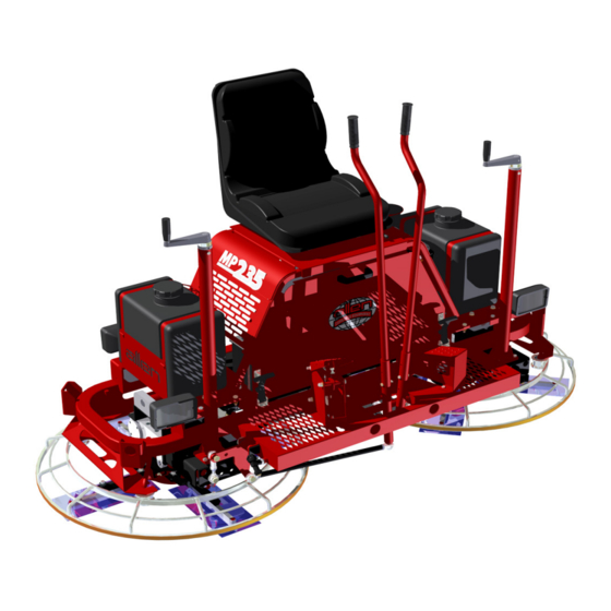
- Page 1 MP235 RIDING TROWEL OPERATIONS & PARTS MANUAL REVISION: 05.2018 | MANUAL PART #: 053383...
- Page 2 This manual, or a copy of it, must be kept with the machine at all times. There is a manual storage container located on the machine for your convenience. 053383; 11/10...
- Page 3 No part of this manual may be reproduced or transmitted in any form or by any means, electronics or mechanical, for any purpose, without the express written permission of Allen Engineering Corporation (AEC). AEC assumes no responsibility or liability for any errors or inaccuracies that may appear in this manual.
-
Page 4: Limited Warranty
Allen reserves the choice to repair or replace. 2. If Allen chooses to replace the part, it will be at no cost to the customer and will be made available to the Allen Distributor, Dealer, or Rental Center from whom the End User purchased the product. -
Page 5: Table Of Contents
Table of Contents Sect No. Title Page Limited Warranty ..........ii Information Contained In This Manual . - Page 6 Table of Contents, continued Parts ........... . 4-1 Factory Service Information .
-
Page 7: Information Contained In This Manual
Complete any warranty requirements as specified by the engine manufacturer in their instructions found inside the manual box located on the back of the riding trowel operator’s seat. Your engine and clutch is not manufactured by Allen Engineering Corporation, Inc, and therefore is not covered under Allen Engineering Corporation, Inc warranty. -
Page 8: Dealer Information
Dealer Information Your Dealer has Allen Engineering Corporation trained mechanics and original Allen replacement parts. Always contact the Allen Dealer who sold you this machine for Allen Certified repairs and replacement parts. Place Allen Dealer information below for future reference... -
Page 9: Ordering Parts
Ordering Parts Section 4.0 contains illustrated parts lists for help in ordering replacement parts for your machine. Follow the instructions below when ordering parts to insure prompt and accurate delivery: All orders for service parts - include the serial number for the machine. Shipment will be delayed if this information is not available. -
Page 10: Model Number - Serial Number Codes
Model Number - Serial Number Codes Manufacturer’s Codes: When ordering parts or requesting service information, you will always be asked to specify the model and serial numbers of the machine. The legends below specifically defines each significant character or group of characters of the Model Number and Serial Number codes. Model Number MODEL SERIES... -
Page 11: Unit Identification
Unit Identification Unit Identification Plate Location: An identification plate listing the model number and the serial number is attached to each unit and is located on the rear lower left side of mainframe. Refer to Figure 1 for serial number and model number location. -
Page 12: Technical Specifications
Technical Specifications Measurements in this manual are in U.S. units and their customary metric units (i.e., metric units contained within brackets [8 mm]). The machine RIGHT-HAND and LEFT-HAND sides are deter- mined by sitting on machine (SOM) facing in the direction the machine will travel when going forward. - Page 13 Technical Specifications, continued • Transmission Type .......Torque Converter Clutch • Drive Belt Type .
-
Page 14: Engine Specifications
Engine Specifications Honda Engine Information • Model ..........GX-690 UTDW •... -
Page 15: Machine Dimensional Specifications
Machine Dimensional Specifications All information, specifications, and illustrations on this page in this manual are subject to change without notice and are based on the latest information at the time of publication. 53 [1346 mm] HEIGHT xiii 053383; 11/10... - Page 16 Power Level Press Overall Overall Maximum dB (A) dB (A) dB (A) m/sec² m/sec² m/sec² MP235 Honda 86.9 86.8 2.76 5.73 3.00 This information was acquired from sound and vibration analysis tests conducted at Allen Engineering Corporation test facilities. 053383; 11/10...
- Page 17 819 South 5th St., Paragould, AR 72450 USA ab lin-pro Authorised Representative in EU: Mr. Thomas Voeler, Femvägsskälet 3, 421 50 Västra Frölunda. Sweden Equipment: MP235 Riding Trowel Description: Ride-on, IC engine powered, concrete smoothing machine. Notified Body: Not required. Harmonized Standards Applied:...
- Page 18 053383; 11/10...
-
Page 19: Safety
SECTION 1 SAFETY Section 1 SAFETY 053383; 11/10... -
Page 20: State Regulations
SECTION 1 State Regulations SAFETY CALIFORNIA PROPOSITION 65 WARNING Gasoline engine exhaust from this product contains chemicals known to the State of California to cause cancer, birth defects and other reproductive harm. 053383; 11/10... -
Page 21: Federal Regulations
SECTION 1 Federal Regulations SAFETY SILICOSIS WARNING Grinding/cutting/drilling of masonry, concrete, metal and other materials with silica in their composition may give off dust or mists containing crystalline silica. Silica is a basic component of sand, quartz, brick clay, granite and numerous other miner- als and rocks. -
Page 22: General Safety Precautions
SECTION 1 General Safety Precautions SAFETY 1.1.1 Safety-Alert Signs This manual contains Safety-Alert Signs, as defined below, which must be followed to reduce the possibility of improper servi ce damage to the equipment or personal injury. Read and follow all Safety-Alert Signs included in this manual. NOTE defines an operating procedure, condition, etc. -
Page 23: Spark Arrestor Notice
SECTION 1 SAFETY Spark Arrestor Notice 1.2.1 Laws Pertaining to Spark Arrestors Some states require that in certain locations arrestors be used on internal combustion engines. A spark arrester is a device designed to prevent the discharge of spark or flames from the engine exhaust. It is often required when operating equipment on forested land to prevent the risk of fires. -
Page 24: Operating Safety
SECTION 1 SAFETY Operating Safety 1.3.1 Operating Safety Familiarity and proper training are required for the safe operation of this equipment! Equipment operated improperly or by untrained personnel can be dangerous! Read the operating instructions contained in both this manual and the engine manual and familiarize yourself with the location and proper use of all controls. - Page 25 SECTION 1 1.3, continued SAFETY Operating Safety 1.3.13 ALWAYS close fuel valve on engines equipped with one when machine is not being operated. 1.3.14 ALWAYS store the equipment properly when it is not being used. Equipment should be stored in a clean, dry location out of the reach of children. 1.3.15 ALWAYS operate the machine with all safety devices and guards in place and in working order.
-
Page 26: Engine Safety
SECTION 1 SAFETY Engine Safety 1.4.1 Engine Safety Internal combustion engines present special hazards during operation and fueling. Read and follow the warning instructions in the engine owner’s manual and the safety guidelines below. Failure to follow the warnings and safety guidelines could result in severe injury or death. 1.4.2 DO NOT run the machine indoors or in an enclosed area such as a deep trench unless adequate ventilation, through such items as exhaust fans or hoses, is... - Page 27 SECTION 1 Service Safety SAFETY 1.5.1 Service Safety Poorly maintained equipment can become a safety hazard! In order for the equipment to operate safely and properly over a long period of time, periodic maintenance and occasional repairs are necessary. 1.5.2 DO NOT attempt to clean or service the machine while it is running.
- Page 28 SECTION 1 SAFETY Safety and Operation Labels The safety and operation labels shown in this section are placed in important areas on the machine to draw attention to potential safety hazards and service information. Should any of these labels become unreadable or damaged, replacement labels can be odered from your dis- tributor.
-
Page 29: Safety And Operation Labels
SECTION 1 1.6, continued SAFETY Safety and Operation Labels This label is a maintenance reminder to grease the thrust bearing daily. This will ensure that the life span of the bearings will be maintained at their optimal preformance level. This label cautions against allowing cleaning agents, surface treatments, or other foreign substances to contaminate drive components. - Page 30 SECTION 1 1.6, continued SAFETY Safety and Operation Labels This label warns of the risk hazards associated with engine exhaust fumes causing heath issues as identified by the State of California. This label states that this equipment was proudly manufactured in the United States of America. This label cautions the operator of pinch points on the machine.
- Page 31 SECTION 1 1.6, continued Safety and Operation Labels SAFETY This label shows the location where hand tools are to be placed while operating the machine. This label warns of sparks created by this machine and that a spark arrestor may be required.
- Page 32 SECTION 1 SAFETY INTENTIONALLY LEFT BLANK 1-14 053383; 11/10...
-
Page 33: Operations
SECTION 2 OPERATIONS Section 2 OPERATIONS 053383; 11/10... - Page 34 This machine is built with user safety in mind. However, it can present hazards if improperly operated and serviced. Follow operating instructions carefully. If you have any questions about operating or servicing this equipment, please contact your Allen Engineering Dealer or AEC Customer Service at 800-643-0095 or 870-236-7751. 053383; 11/10...
-
Page 35: Introduction
OPERATIONS 2.1.1 Description The MP235 riding trowel is a modern high production machine. Finishing rates will vary depending on the operators skill and job conditions. This riding trowel has eight finishing blades. The standard duty gearboxes are designed to provide exceptional performance with low maintenance and trouble free use under some of the worst conditions. -
Page 36: Start Up Procedures
SECTION 2 Start Up Procedures OPERATIONS 2.9.1 Before Starting Procedures Before starting the riding trowel check for the following: Oil level in engine. Oil level in riding trowel gearboxes. Fuel level in fuel tank. Condition of riding trowel arms and blades. Verify that daily maintenance of grease points have been performed. - Page 37 SECTION 2 2.2, continued Start Up Procedures OPERATIONS 12V Accessory LOW OIL LIGHT LIGHT SWITCH KEY SWITCH HOURMETER ENGINE CHOKE FIGURE 2.2.1 TOP VIEW OF CONTROLS 053383; 11/10...
-
Page 38: Operating Instructions
2.3.1 Operating The Riding Trowel To utilize your Allen Engineering MP235 Rider to its fullest capacity the machine should be driven in the direction the operator is facing. This will finish the widest possible area while giving the operator an excellent view of the slab surface about to be troweled. - Page 39 SECTION 2 2.3, continued Operating Instructions OPERATIONS With the operator in the seat, show him the functions of the joysticks [B] and [C] and how to start the machine. Refer to Figure 2.3.1. A hard level concrete slab with water on the surface is an ideal place for an operator to practice with the machine.
- Page 40 SECTION 2 2.3, continued Operating Instructions OPERATIONS 2.3.3 Steering The Riding Trowel A slight "feathering motion" forward and backward with the left hand joystick is required to move the machine in a straight path to the left or right while operating the right hand joystick.
- Page 41 SECTION 2 2.3, continued Operating Instructions OPERATIONS 2.3.4 Pitch Adjustment Different pitch angles are needed as you work the different stages of the concrete. Refer to Figure 2.3.4 table below. When changing or setting pitch (angle of trowel blades), slow the machine down, set the desired degree of pitch on the left side of the machine and then adjust the right side to match.
- Page 42 SECTION 2 2.3, continued Operating Instructions OPERATIONS 2.3.5 Steering Response Adjustment There are three settings on this Riding Trowel for steering response. Some operators like a fast response to steering while others would rather have a slower response when pressure is applied to the operator joysticks. The fol- lowing illustrations show each appropriate setting on the lower control arms to achieve the desired response.
-
Page 43: Service
SECTION 3 SERVICE Section 3 SERVICE 053383; 11/10... -
Page 44: Periodic Maintenance
SECTION 3 Periodic Maintenance SERVICE Periodic Maintenance Schedule The table below list basic trowel and engine maintenance. Refer to OEM engine manufacturer's Operation Manual for additional information on engine maintenance. A copy of the engine operator's manual was supplied with the machine when it was shipped. -
Page 45: Trowel Gearbox
Replace fill plug after proper level has been achieved. Fill so that there is oil 1/2 way in the sight glass. Use Allen Oil only. Each Gearbox has a grease fitting on top cover that must be greased (2 SHOTS ONLY) every 300 operating hours. -
Page 46: Drive Belt
SECTION 3 Drive Belt SERVICE 3.3.0 Drive Belt Maintenance The drive belts MUST be free from oil and foreign contaminants to prolong life. 3.3.1 To Replace The Drive Belt: Place the trowel on a flat, level surface with the blades pitched flat. Disconnect the battery. - Page 47 SECTION 3 3.3, continued SERVICE Drive Belt REMOVE POSITIVE BATTERY CABLE FIGURE 3.3.1 BATTERY DISCONNECT 053383; 11/10...
- Page 48 SECTION 3 3.3, continued SERVICE Drive Belt DRIVEN PULLEY CLUTCH COVER BELT DRIVELINE BOLT FIGURE 3.3.2 BELT REPLACEMENT 053383; 11/10...
- Page 49 SECTION 3 3.3, continued SERVICE Drive Belt FLEX COUPLER BEARING MOUNT HARDWARE FIGURE 3.3.3 BELT REPLACEMENT 053383; 11/10...
-
Page 50: Control Lever Adjustment
SECTION 3 Control Lever Adjustment SERVICE Control Lever Adjustment Procedure Be sure that the trowel is on a level surface. The control levers should line up evenly. If levers appear out of adjustment they can be re-adjusted forward or backwards as follows: Trowel must be placed on flat level surface that fully supports the blades on both rotors. - Page 51 SECTION 3 3.4, continued SERVICE Control Lever Adjustment FIGURE 3.4.1 CONTROL LEVER ADJUSTMENT 053383; 11/10...
- Page 52 SECTION 3 Right Hand Control Lever Adjust SERVICE RH Control Lever Adjustment Right Or Left Procedure The right hand lever should be set to the same angle as that of the left to form a "V". If levers become out of adjustment adjust the right hand lever as follows: Remove jam nuts [D].
-
Page 53: Right Hand Control Lever Adjust
SECTION 3 3.5, continued Right Hand Control Lever Adjust SERVICE “V” FORM There should be a 10” gap at the top of the joysticks. JOYSTICK LOCATIONS FIGURE 3.5.1 “V” FORM ORIENTATION LOWER CONTROL FIGURE 3.5.2 RIGHT HAND CONTROL ADJUSTMENT 3-11 053383;... -
Page 54: Lift Lever Adjustment
SECTION 3 Lift Lever Adjustment SERVICE Lift Lever Adjustment Procedure Damage to and/or replacement of a trowel arm can change the adjustment of the lift lever. This can unbalance the trowel arms and cause the riding trowel to wobble during operation. To operate smoothly the lift lever on all trowel arms must be adjusted the same to ensure that the riding trowel is balanced correctly. - Page 55 SECTION 3 3.6, continued SERVICE Lift Lever Adjustment TROWEL ARM BLADE FIGURE 3.6.1 PRESSURE PLATE LOCATION SPIDER BOSS FIGURE 3.6.2 FASTENER HARDWARE REMOVAL 053383; 11/10 3-13...
- Page 56 SECTION 3 Transporting Trowel SERVICE Transporting Trowel Procedures Optional dolly jacks are available for short moves or to aid in servicing the trowel. Install dolly jacks as follows: Inspect dolly jack for serviceability and damage. Place riding trowel on firm level ground. Tie steering levers [I] to frame to prevent them from tipping forward when trowel is being lifted.
- Page 57 SECTION 3 3.7, continued SERVICE Transporting Trowel FIGURE 3.7.2 FIGURE 3.7.3 FRONT DOLLY JACK REAR DOLLY JACK LOCATION LOCATION 053383; 11/10 3-15...
-
Page 58: Transporting Trowel
SECTION 3 3.7, continued SERVICE Transporting Trowel The dolly jack lifting system is designed for short moves and to aid in servicing the trowel. It is not a substitute for a towing system or trailer. An optional lifting bridle [N] is available and recommended for lifting the trowel. - Page 59 SECTION 3 3.7, continued SERVICE Transporting Trowel FIGURE 3.7.7 LIFTING HOOK LOCATION 053383; 11/10 3-17...
-
Page 60: Battery Jump Start
SECTION 3 Battery Jump Start SERVICE Battery Jump Start Procedures Occasionally it may be necessary to jump start a weak battery. If jump starting is necessary the following procedure is recommended to prevent starter damage, battery damage, and personal injury. Jump starting a battery incorrectly can cause the battery to explode resulting in severe personal injury or death. - Page 61 SECTION 3 3.8, continued SERVICE Battery Jump Start BATTERY FIGURE 3.8.1 BATTERY LOCATION 053383; 11/10 3-19...
- Page 62 SECTION 3 Notes SERVICE 3-20 053383; 11/10...
- Page 63 Section 4 PARTS...
- Page 64 SECTION 4 Factory Service Information PARTS This section contains the illustrated drawings and parts list for help in identifying and/or ordering replacement parts for your machine. Follow the instructions in the front section of this manual “Ordering Parts” when ordering replacement parts to insure prompt and accurate delivery. The Right Hand (RH) and/or Left Hand (LH) orientations are defined from the operator’s view of sitting on machine (SOM).
- Page 65 SECTION 4 Replacement Parts Procedures PARTS We recommend AEC quality replacement parts, available from the AEC Customer Service Department or your nearest AEC Dealer. Part numbers are subject to change without notice. Part numbers might be different outside of the United States of America. Use part numbers listed in the applicable parts list table when you place your order.
- Page 66 4.1 Illustration SECTION 4 Seat Frame Unit - 053225 PARTS 053383 - 07/2017...
- Page 67 053220 MP235 DECAL 053440 DECAL, PROPOSITION 65 WARNING (SP) 053447 DECAL, HAND TOOL AREA (SP) 053450 DECAL, LIGHTS (SP) 053451 DECAL, OIL (SP) 053452 DECAL, 12V ACCESSORY (SP) 053454 DECAL, MANUALS (SP) 053455 DECAL, ALLEN F/ SEAT 053383 - 07/2017...
- Page 68 4.2 Illustration SECTION 4 Main Frame Unit - 053161 PARTS Bottom View for clarity 053383 - 07/2017...
- Page 69 BAR, BEARING HOUSING ALUM 048560 BEARING, I-GLIDE FLANGE 048921 STRAP, TANK MSP425 053138 COVER PLATE 053160 WELD’T, MAIN FRAME MP235 053178 MOUNTING PLATE F/ TANK 053188 ASSY, VANGUARD THROTTLE PEDAL 053197 BRKT, THROTTLE CABLE 053200 TANK, 6 GALLON GAS, EPA...
- Page 70 4.3 Illustration SECTION 4 Steering System PARTS 053383 - 07/2017...
- Page 71 LEVER, STEERING, LH 53115 STEERING TUBE WMNT, RH 53120 PIVOT ARM F/ STEERING 53124 STEERING LEVER WMNT 53160 WELD’T, MAIN FRAME MP235 53162 ROTOR ASSEMBLY, RH 53164 ROTOR ASSEMBLY, LH MP235 53174 SHAFT, 18” LONG STEERING LINKAGE 53179 PIVOT ROD...
- Page 72 4.4 Illustration SECTION 4 Spray System PARTS Bottom View for clarity. 4-10 053383 - 07/2017...
- Page 73 ELBOW, 1/4 PUSHLOK x 1/4 NPT PLASTIC 048246 HOSE, 3/8” WATER LINE 7.5’ 048652 TEE, PLASTIC 1/4 x 1/4 x 1/4 048921 STRAP, TANK MSP425 053160 WELD’T, MAIN FRAME MP235 053178 MOUNTING PLATE F/ TANK 053445 DECAL, RETARDANT ONLY (SP) 4-11 053383 - 07/2017...
- Page 74 4.5 Illustration SECTION 4 Pitch Control Assembly PARTS Tube not shown for clarity. 4-12 053383 - 07/2017...
- Page 75 PLUNGER, 1/4-20 BALL 036914 BUSHING, CABLE ASSY 100340 BEARING, NAT-1220 THRUST 026541 CRANK HANDLE & SCREW SHAFT ASY 012869 FSTN, SHSS 1/4-20 X 3/8 032377 DECAL, F/ PITCH CONTROL TUBE 053442 DECAL, ALLEN VERTICAL BRUSHED CHROME 4-13 053383 - 07/2017...
- Page 76 4.6 Illustration SECTION 4 Engine System - GX690 Honda PARTS 4-14 053383 - 07/2017 DETAIL B SCALE 2...
- Page 77 4.6 Parts List SECTION 4 Engine System - GX690 Honda PARTS ITEM PART # DESCRIPTION 010035 FSTN, HHCS 3/8-16 X 3/4 010053 FSTN, HHCS 7/16-14 X 1-1/4 010072 FSTN, HHCS 1/2-13 X 2-1/4 GR 5 010083 FSTN, FW 3/8 010084 FSTN, FW 7/16 010091 FSTN, LW 3/8...
- Page 78 4.7 Illustration SECTION 4 Driveline System PARTS Engine Plate Member 4-16 053383 - 07/2017...
- Page 79 PULLEY, MSP425 DRIVEN 050069 ENGINE PLATE WELDMENT MP215 050070 SHAFT, DRIVE 17 1/2 F/LOCK BEARING 053162 ROTOR ASSEMBLY, RH 053164 ROTOR ASSEMBLY, LH MP235 053172 ASSY, PS1200 U-JOINT 053193 SPACER, BEARING, 1 3/8” 053194 SPACER, BEARING, 4 3/4” 4-17 053383 - 07/2017...
-
Page 80: Electrical Schematic
4.8 Electrical Schematic SECTION 4 PARTS 4-18 053383 - 07/2017... - Page 81 4.8 Electrical Schematic (cont’d) SECTION 4 PARTS 4-19 053383 - 07/2017...
- Page 82 4.9 Illustration SECTION 4 Right Hand Rotor Assembly PARTS 4-20 053383 - 07/2017...
- Page 83 4.9 Parts List SECTION 4 Right Hand Rotor Assembly PARTS ITEM PART # DESCRIPTION 053162 ROTOR ASSEMBLY, RH MP235 010023 FSTN, HHCS 5/16-18 X 3/4 GR 5 010024 FSTN, HHCS 5/16-18 X 2 GR 5 010035 FSTN, HHCS 3/8-16 X 3/4 010090...
- Page 84 4.10 Illustration SECTION 4 Left Hand Rotor Assembly PARTS 4-22 053383 - 07/2017...
- Page 85 4.10 Parts List SECTION 4 Left Hand Rotor Assembly PARTS ITEM PART # DESCRIPTION 053164 ROTOR ASSEMBLY, LH MP235 010023 FSTN, HHCS 5/16-18 X 3/4 GR 5 010024 FSTN, HHCS 5/16-18 X 2 GR 5 010035 FSTN, HHCS 3/8-16 X 3/4 010090...
- Page 86 4.11 Illustration SECTION 4 Right Hand Spider Assembly PARTS 4-24 053383 - 07/2017...
- Page 87 4.11 Parts List SECTION 4 Right Hand Spider Assembly PARTS ITEM PART # DESCRIPTION 024813 SPIDER ASSY, 900-SFC RH-SOM 012990 FSTN, CABLT 3/8-16 X 1-1/4” 015682 FSTN, LW EXT STAR 3/8 015683 BOLT, 3/8-16 X 7/8 DOG PT HEX HD CAP 015684 FSTN, NUT HEX JAM 3/8-16 015686...
- Page 88 4.12 Illustration SECTION 4 Left Hand Spider Assembly PARTS 4-26 053383 - 07/2017...
- Page 89 4.12 Parts List SECTION 4 Left Hand Spider Assembly PARTS ITEM PART # DESCRIPTION 015893 SPIDER ASSY, 900-SFC LH-SOM 012990 FSTN, CABLT 3/8-16 X 1-1/4” 015682 FSTN, LW EXT STAR 3/8 015683 FSTN, 3/8-16 X 7/8 DOG CAP SCREW 015684 FSTN, NUT HEX JAM 3/8-16 015686 FSTN, SQHSS 3/8-16 X 1...
- Page 90 4.13 Illustration SECTION 4 RH Standard Duty Gearbox PARTS Torque to 22 Ft. Lbs. Grease this area forre-assembly only. 4-28 053383 - 07/2017...
- Page 91 RH Standard Duty Gearbox PARTS ITEM PART # DESCRIPTION 001003 GREASE, MOBILITH SCH 220 .094 048299 OIL, ALLEN ENGINEERING GEARBOX .757/LT 010498 PLUG, 3/8 NPT BI SQ HD PIPE 010513 FITTING, 1/4-28 NPT STR GREASE 012953 PLUG, 3/4 NPTF BI SQ HD PIPE...
- Page 92 4.14 Illustration SECTION 4 LH Standard Duty Gearbox PARTS Torque to 22 Ft. Lbs. Grease this area forre-assembly only. 4-30 053383 - 07/2017...
- Page 93 LH Standard Duty Gearbox PARTS ITEM PART # DESCRIPTION 001003 GREASE, MOBILITH SCH220 .094 048299 OIL, ALLEN ENGINEERING GEARBOX .757/LT 010498 PLUG, 3/8 NPT BI SQ HD PIPE 010513 FITTING, 1/4-28 NPT STR GREASE 012953 PLUG, 3/4 NPTF BI SQ HD PIPE 015204...
- Page 94 4.15 Illustration SECTION 4 Accessory - Pro Dolly Jack System PARTS 4-32 053383 - 07/2017...
- Page 95 4.15 Parts List SECTION 4 Accessory - Pro Dolly Jack System PARTS ITEM PART # DESCRIPTION 027684 SET, PRO DOLLY JACK 017751 WASHER, 3/8 FLAT 010133 PIN, 3/16 X 2 COTTER 015692 CAP, 1/4 RED GREASE 010464 NUT, 3/8-16 NYLOCK LOCK 024628 SPACER, DOLLY JACK WHEEL 026728...
- Page 96 4.16 Illustration SECTION 4 Accessory - Non-standard Items PARTS 4-34 053383 - 07/2017...
- Page 97 4.16 Parts List SECTION 4 Accessory - Non-standard Items PARTS ITEM PART # DESCRIPTION 039218 PAN MILD DISHED STEEL, 36-1/4” EDGER 046399 COMPODISK, 36-1/4” OD X 3/4” (4) EDGER 035461 BRIDLE, 2500 LB 5 FT SLING LIFT 4-35 053383 - 07/2017...
-
Page 98: Tools
4.17 Illustration SECTION 4 Tools - Service PARTS 4-36 053383 - 07/2017... - Page 99 4.17 Parts List SECTION 4 Tools - Service PARTS ITEM PART # DESCRIPTION 016863 JIG, TROWEL ARM ALIGNMENT 035688 KIT, STD 4-ARM SPIDER PULLER 4-37 053383 - 07/2017...
-
Page 100: Gearbox Seal Kit
4.18 Gearbox Seal Kit SECTION 4 PARTS ITEM PART NO. DESCRIPTION 066979 KIT, GEARBOX OIL SEAL FOR 026442 & 026443 015670 SEAL, OIL CR# 7455V (p) 015671 SEAL, OIL CR# 133661 (p) 015673 O-RING, 15/16 X 1 - 3/16 X 1/8 BUNA 015660 O-RING, GEAR BOX END CAPS (p) 4-38... - Page 101 Notes SECTION 4 PARTS 4-39 053383 - 07/2017...
- Page 102 INTENTIONALLY BLANK 053383; 11/10...
- Page 103 P.O. BOX 819 PARAGOULD, AR 72451 USA 800.643.0095 (USA ONLY) / 870.236.7751 FAX: 800.643.0097 (USA ONLY) / 870.236.3934 WWW.ALLENENG.COM CONNECT WITH US ON...
Need help?
Do you have a question about the MP235 and is the answer not in the manual?
Questions and answers