Table of Contents
Advertisement
Quick Links
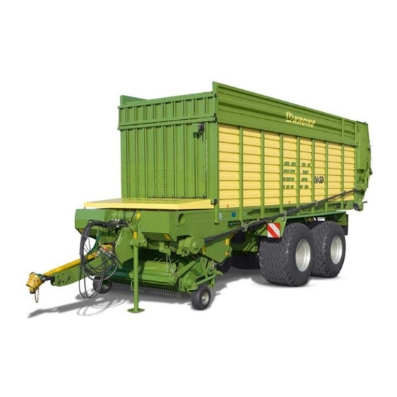
Short-cut loading wagon / Short-cut
MX 310
< v > T - T y p 1 < / v >
GL< / v >
MX 350
< v > T - T y p 2 < / v >
GL< / v >
< v > T - T y p 3 < / v >
MX 310
GD< / v >
MX 350
< v > T - T y p 4 < / v >
GD< / v >
< v > T - T y p 5 < / v > < / v >
(< v > T - a b M a s c h . - N r . < / v >
from serial
no.< / v >
Order
< v > T - B e s t e l l - N r . < / v >
no.< / v >
: 150 000 122 02 en
< v > B - T i t e l b i l d < / v >
feeder wagon
: 785 000)
< v > T - T y p 6 < / v > < / v >
< v > T - T y p 7 < / v > < / v >
< v > T - T y p 8 < / v > < / v >
< v > T - T y p 9 < / v > < / v >
< v > T - T y p 1 0 < / v > < / v >
< / v >
18.03.2010
Advertisement
Table of Contents


Need help?
Do you have a question about the MX 310 GL and is the answer not in the manual?
Questions and answers