
Related Manuals for Winmate IA71


Summary of Contents for Winmate IA71
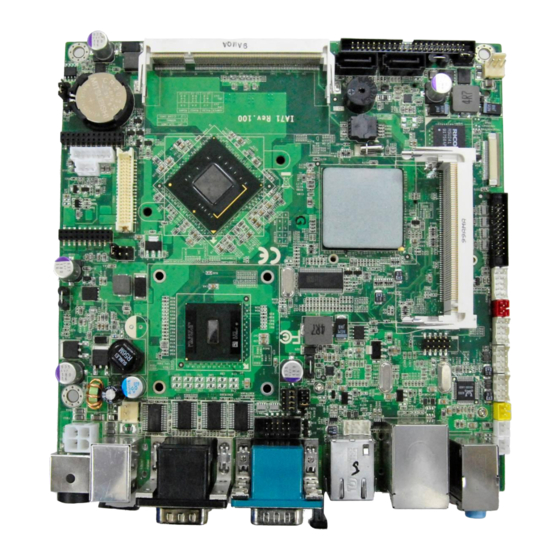
- Page 1 IA71 Motherboard ® Mini-ITX Fan SBC with Intel ATOM N270 1.6GHz Processor, VGA, LCD, Giga Ethernet, Mini-PCI, PCI and PCMCIA Slot Interface. USER MANUAL Version 1.0...
- Page 2 Operation of this equipment in a residential area is likely to cause harmful interference in which case the user will be required to correct the interference at him own expense. IA71 Motherboard User Manual V1.0...
- Page 3 (e. g., with A for October, B for November and C for December). For example, the serial number 1W07Axxxxxxxx means October of year 2007. IA71 Motherboard User Manual V1.0...
- Page 4 Customer Service We provide service guide for any problem as follow steps: 1. Visit our website (www.winmate.com.tw) to find updated information of the product. 2. Contact with your local distributor, sales representative, or our customer service center for technical support if you need additional assistance. You may have to prepare the following information in advance before you call us:...
- Page 5 As a safety precaution, use a grounding wrist strap at all times. Place all electronic components in a static-dissipative surface or static-shielded bag when they are not in the chassis. IA71 Motherboard User Manual V1.0...
- Page 6 F. The equipment has obvious signs of breakage. 15. Do not leave this equipment in an uncontrolled environment where the storage temperature is below -20° C (-4°F) or above 60° C (140° F). It may damage the equipment. IA71 Motherboard User Manual V1.0...
- Page 7 Revision History Version Date Note Author 2010.04.01 Initial Draft Sky Chen 2010.04.06 First Version Bruce Huang IA71 Motherboard User Manual V1.0...
-
Page 8: Table Of Contents
NSTALLATION OF THERNET RIVER CHAPTER 7AUDIO DRIVER INSTALLATION ........45 ................45 NTRODUCTION ........... 45 NSTALLATION OF UDIO RIVER CHAPTER 8 AMI BIOS SETUP............48 ................. 48 TARTING ETUP ..............49 YSTEM VERVIEW ..............50 DVANCED ETTING VIII IA71 Motherboard User Manual V1.0... - Page 9 PCI/P P ................... 66 ..................72 ................... 76 ECURITY ..................77 HIPSET ........... 79 OARD ARALLEL RINTER ..................81 NOTE1: DIGITAL I/O SAMPLE CODE..........84 IA71 Motherboard User Manual V1.0...
-
Page 10: General Information
General Information This chapter includes IA71 Motherboard background information. Sections include: Introduction Feature Motherboard Specification Function Block Board Dimensions IA71 Motherboard User Manual V1.0... -
Page 11: Chapter 1 General Information
PCMCIA slot and Mini-PCI I/O ports, two SATA connectors, and eight Hi-Speed USB 2.0 port connectors. Thus, IA71 SBC is designed to satisfy most of the applications in the industrial computing market, such as Gaming, POS, KIOSK, Industrial Automation, and Programmable Control System. It is a compact design to meet the demanding performance requirements of today’s business and... -
Page 12: Motherboard Specifications
Operating temperature: 0 deg. C to 60 deg. C Mechanical & Operating Humidity: 30 ~ 90% Relative humidity, environmental non-condensing Certification: CE, FCC, RoHS One parallel port with Extended Capability Port(ECP) and Parallel Port Enhanced Parallel Port(EPP) Support IA71 Motherboard User Manual V1.0... -
Page 13: Function Block
66MHz Hub Interface 1.5 ATA100 2x 1GB/s 1 x IDE Host Intel ICH7M 480MB/s 3GB/s SATA II 1, SATAII 2 Audio 33MHz Mini PCI Super IO ROM FWH Secondary IO 1 x Parallel Port 1 x PCMCIA Port IA71 Motherboard User Manual V1.0... -
Page 14: Board Dimensions
Board dimensions IA71 Motherboard User Manual V1.0... - Page 15 Installations This chapter provides information about how to use the jumps and connectors on IA71 Motherboard. The Sections include: Install the I/O shield Install and remove Memory Module Connect the IDE cable Connect the SATA cable Connect internal headers Connectors on IA71 Motherboard...
-
Page 16: Chapter 2 Installations
ESD protection by wearing an antistatic wrist strap and attaching it to a metal part of the computer chassis. When you install and test the IA71 Motherboard, observe all warnings and cautions in the installation instructions. -
Page 17: Installing And Removing Memory Modules
2.2. Installing and Removing Memory Modules IA71 motherboard supports one 200-pin SODIMM slot. The socket supports up to 2GB DDR2 400/533 SDRAM. Press downwards on SODIMM until the retaining clips at both ends fully snap back in place and the SODIMM is properly seated. - Page 18 LAN link is not established LAN link is established Blinking LAN activity is occurring B (Yellow) 10 Mbits/s data rate is selected On (steady state) 100 M bits/s data rate is selected 2.3.6. USB ports IA71 Motherboard User Manual V1.0...
- Page 19 The audio line out connector where located on rear side of the box is designed to power headphones or amplified speakers only. Poor audio quality occurs if passive (non-amplified) speakers are connected to this output. IA71 Motherboard User Manual V1.0...
-
Page 20: Jumpers And Connectors
2.4. Jumpers and Connectors Audio LAN 2 LAN1 PS/2 COM3 DC Jack PCMCIA SATA2 SATA1 SO-DIMM1 IDE1 NB_FAN CON4 MINI PCI CON3 Parallel Port PANEL1 CON11 CPU _FAN CON10 ATX12V1 Audio USB2 USB1 CON7 IA71 Motherboard User Manual V1.0... -
Page 21: Jumper Setting
Clear CMOS. Users remember to setting jumper back to Normal before turning on the power supply. Default: 2 short 3. Clear CMOS Normal Pin No. Functions 1 Short 2 Clear CMOS 2 Short 3 Normal IA71 Motherboard User Manual V1.0... - Page 22 2.5.4. CON5: LCD Panel Voltage Select CON5 can be configured to operate in 3.3Volts / 5Volts / 12Volts mode. 3.3Volts 5Volts 12Volts Pin No. Functions 1 Short 2 3.3Volts Selected 3 Short 4 5Volts Selected 5 Short 6 12Volts Selected IA71 Motherboard User Manual V1.0...
-
Page 23: Connectors And Pin Assignment
5V External Power(Red) 2x1 header, pitch 2.54mm 5V/12V External Power header ,pitch 2.54mm CON6 Digital I/O 10 pin Digital I/O function ATX12V1 12V DC Connector 2x2 Pin Connecter CON9 12V DC Connector 4 Pin Connecter IA71 Motherboard User Manual V1.0... - Page 24 Pin No. SYMBOL LCDVDD LVDS_LTX0- LCDVDD LVDS_LTX0+ LCDVDD LVDS_LTX1- LVDS_LTX1+ LVDS_LTX2- LVDS_LTX2+ LVDS_LCLK- LCDS_LCLK LVDS_UTX0- LVDS_UTX0+ LVDS_UTX1- LVDS_UTX1+ LVDS_UTX2- LVDS_UTX2+ LVDS_UCLK- LVDS_UCLK 2.6.2 JP3: Digital Panel Backlight Brightness Control Pin No. SYMBOL Black Light Control IA71 Motherboard User Manual V1.0...
- Page 25 2.6.3 CON4: Digital Panel Backlight Control Pin No. SYMBOL +12V +12V +12V Black Light Control Black Light EN 5V 2.6.4 PSKBM1: PS2 Keyboard/Mouse Connector PS/2 Keyboard PS/2 Mouse Pin No. SYMBOL Pin No. SYMBOL KDATA MDATA Ground Ground KCLK MCLK IA71 Motherboard User Manual V1.0...
- Page 26 NDSRA NRTSA NCTSA NRIA DAC_SDAT0 3VHSYNC0 3VVSYNC0 DAC_SCL0 2.6.6 CON7: Serial port COM2 The serial port COM2, which is Winbond I/O support, is RS232 only. SYMBOL SYMBOL NDSR1A NDCD1A NRTS1A NRXD1A NCTS1A NTXD1A NRI1A NDTR1A IA71 Motherboard User Manual V1.0...
- Page 27 FK_NRTS1 FK_NRTS2 FK_NCTS1 FK_NCTS2 FK_NRI1 FK_NRI2 2.6.8 AUDIO401: Audio Jack ( Pin-header ) SYMBOL Color Signal Blue Line In Green Line Out Pink Microphone In Pin-Header C0~C4 Line in B1~B4 Line out A1~A4 Mic in IA71 Motherboard User Manual V1.0...
- Page 28 CN12.45 IOWR# CN12.46 CN12.47 CN12.48 CN12.49 CN12.50 CN12.51 CAVCC CN12.52 CAVPP CN12.53 CN12.54 CN12.55 CN12.56 CN12.57 VS2# CN12.58 RESET CN12.59 WAIT# CN12.60 INPACK# CN12.61 REG# CN12.62 BVD2 CN12.63 BVD1 CN12.64 CN12.65 CN12.66 CN12.67 CD2# CN12.68 IA71 Motherboard User Manual V1.0...
- Page 29 GND5 DIOR# GND6 IO_RDYD CSEL DACK# GND7 IOCS16# CBL_ID# DCS#1 DCS#3 DASP# GND8 +5V1 +5V2 2.6.10 USB1/2: USB PIN HEADER USB1/2 SYMBOL SYMBOL USBVCC USBVCC USB_P6- USB_P7- USB_P6+ USB_P7+ 2.6.11 NB_FAN1/CPU_FAN1: FAN CONNECTOR NB_FAN CPU_FAN IA71 Motherboard User Manual V1.0...
- Page 30 2.6.12 PANEL1: Front Panel System Function Connector SYMBOL SYMBOL HD_LED+ PW_LED+ HD_LED- PW_LED- RT_BT1 PW_BT1 RT_BT2 PW_BT2 5VSB RSEV 2.6.13 J2/J3: Front Audio IA71 Motherboard User Manual V1.0...
- Page 31 2.6.14 CON10/CON11/J4: External Power CON10 CON11 2.6.15 PWIN1: DC Jack 2.6.16 ATX12V1: 12V DC Connector SYMBOL Ground Ground +12V +12V 2.5.17 Digital I/O Connector SYMBOL SYMBOL Out1 Out3 Out0 Out2 IA71 Motherboard User Manual V1.0...
- Page 32 2.5.18 Parallel Port Box Header LPT1 IA71 Motherboard User Manual V1.0...
- Page 33 Graphic Driver Installation This chapter offers information about the chipset software Installation utility Installation of Graphic Driver Panel Resolution Setting IA71 Motherboard User Manual V1.0...
-
Page 34: Chapter 3 Graphic Driver Installation
Chapter 3 Graphic Driver Installation 3.1. Standard CMOS Feature IA71 Motherboard is equipped with Intel 945GSE / ICH7M Companion Device. The Intel Graphic Drivers should be installed first, and it will enable “Video Controller (VGA compatible). Follow the instructions as below to complete the system’s installation. - Page 35 Step.3. Click on “Next“ to install the Graphic Driver. Step.4. Click on “Next “to install Driver. IA71 Motherboard User Manual V1.0...
- Page 36 Step.5. Click on “Yes “to accept all of the terms of the License Agreement. Step.6. Click on “Next “to install Driver. IA71 Motherboard User Manual V1.0...
- Page 37 Step.7. Click on “Next “ to install Driver. Step.8. Click on “Yes, I want to restart this computer now“, and proceed. IA71 Motherboard User Manual V1.0...
-
Page 38: Panel Resolution Setting
3.2. Panel Resolution Setting Step.1. Right-click the mouse on the desktop, and then click the “Properties”. Step.2. In the Display “Properties” window, click the “Settings” tab. Step.3. Click on the “Monitor” tab. IA71 Motherboard User Manual V1.0... - Page 39 Step.4. Do not tick on the “Hide modes that this monitor cannot display” tab to remove this option. Step.5. Click on the “Setting”, then you could choose 32bit color qualify. IA71 Motherboard User Manual V1.0...
- Page 40 Chipset Driver Installation This chapter offers information about the chipset software Installation utility Installation of the Chipset Driver Further information IA71 Motherboard User Manual V1.0...
-
Page 41: Chapter 4 Chipset Driver Installation
4.1. Standard CMOS Features Setp.1. Insert the CD that comes with the accessories with of the motherboard into the CD-ROM. Open the file folder named “Chipset Driver”. Setp.2. Click on the “infinst_auto.exe“to install the driver. IA71 Motherboard User Manual V1.0... - Page 42 Setp.3. Click on “Next“ to install the driver. Click on “Yes “ to accept all terms of the License Agreement Setp.4. IA71 Motherboard User Manual V1.0...
- Page 43 Click on “Next“ to install the driver. Setp.5. Setp.6. Click on “Next“ to install the driver. IA71 Motherboard User Manual V1.0...
- Page 44 Step.7. Click on “Yes, I want to restart this computer now“, to proceed. IA71 Motherboard User Manual V1.0...
-
Page 45: Ethernet Driver Installation
Ethernet Driver Installation This chapter offers information about the Ethernet software installation utility. Sections include: Introduction Installation of the Ethernet Driver IA71 Motherboard User Manual V1.0... -
Page 46: Chapter 5 Ethernet Driver Installation
Chapter 5 Ethernet Driver Installation 5.1. Introduction IA71 Motherboard is equipped with the Realtek RTL8111B Gigabit Ethernet controller combines a triple-speed IEEE 802.3 compliant Media Access Controller (MAC) with a triple-speed Ethernet transceiver, PCI Express bus controller, and embedded memory inside. -
Page 47: Installation Of Ethernet Driver
5.2. Installation of Ethernet Driver The Users must to make sure which operating system you are using now under the IA71 Motherboard’s infrastructure before installing the Ethernet drivers. Follow the steps as below to complete the installation of the Realtek RTL8111B LAN drivers’... - Page 48 Step.3. Click on “Next“ to install the driver. Step.4. Click on “Install“ to install the driver. IA71 Motherboard User Manual V1.0...
- Page 49 Setp.5. Click on “Finish“ to finish the installation. IA71 Motherboard User Manual V1.0...
- Page 50 PCMCIA driver installation This chapter offers information about the PCMCIA software installation utility. Sections include: Introduction Installation of the PCMCIA Driver IA71 Motherboard User Manual V1.0...
-
Page 51: Chapter 6 Pcmcia Driver Installation
6.1 Introduction of PCMCIA The Users must to make sure which operating system you are using now under the IA71 Motherboard’s infrastructure before installing the PCMCIA drivers. Follow the steps as below to complete the installation of the CardBus_R5U241 PCMMCIA drivers’ program. You will quickly complete the installation. - Page 52 Step.2 Click on “Next“ to install the driver. Step.3 Click on “install “ to continue. IA71 Motherboard User Manual V1.0...
- Page 53 After you have installed the PCMCIA driver, please click ”Finish” to continue. Step.5 The system will ask you to restart the computer after installation, please click on” Yes, I want to restart the computer now” and click “finish” to end the installation IA71 Motherboard User Manual V1.0...
-
Page 54: Audio Driver Installation
Audio Driver Installation This chapter offers information about the Audio software installation utility. Sections include: Introduction Installation of the Audio Driver IA71 Motherboard User Manual V1.0... -
Page 55: Chapter 7Audio Driver Installation
PCs. Installation of Audio Driver The users must to make sure which operating system you are using in the IA71 Motherboard before installing the Audio drivers. Follow the steps as below to complete the installation of the Realtek ALC655 Audio drivers. - Page 56 Step.2. Click on “Next“ to install the driver. Step.3. Click on “Yes, I want to restart my computer now” to finish the installation. IA71 Motherboard User Manual V1.0...
- Page 57 AMI BIOS Setup This chapter describes how to set up the BIOS configuration IA71 Motherboard User Manual V1.0...
-
Page 58: Chapter 8 Ami Bios Setup
You can always return to the Main setup image by selecting the Main tab. There are two Main Setup options. They are described in this section. The Main BIOS Setup image is shown as below. IA71 Motherboard User Manual V1.0... -
Page 59: System Overview
System Date using the <Arrow> keys. Enter new values through the keyboard. Press the <Tab> key or the <Arrow> keys to move between fields. The date must be entered in MM/DD/YY format. The time must be entered in HH:MM:SS format IA71 Motherboard User Manual V1.0... -
Page 60: Advanced Setting
Advanced Setting CPU Configuration Press “Enter” to the CPU Configuration setting. CPU configuration is different from writing an executable program. It is equivalent IA71 Motherboard User Manual V1.0... - Page 61 The executing program has no way to change under this configuration. IDE/SATA Configuration IDE Channel I/O Master While entering setup image, the BIOS automatically detects the presence of IDE device. This displays the status of IDE device auto-detection. IA71 Motherboard User Manual V1.0...
- Page 62 IDE device type. Select CD-ROM if you are specifically configuring a CD-ROM drive. Select ARMD (ATAPI Removable Media Device) if your device either is ZIP, LS-120, or MO drive. The options: [Not Installed], [Auto], [CD/ DVD], [ARMD]. IA71 Motherboard User Manual V1.0...
- Page 63 LBA/Large Mode Enabling LBA causes Logical Block Addressing to be used in place of Cylinders, Heads and Sectors. The options: [Disabled], [Auto]. Block (Multi-Sector Transfer) “Controls” are enabled of multi-sector transferring, if supported. The options: [Disabled],[Auto]. IA71 Motherboard User Manual V1.0...
- Page 64 PIO Mode It indicates the type of PIO (Programmed Input/Output). DMA Mode It indicates the type of Ultra DMA. The options: [Auto], [SWDMan], [MWDMAn], [UDMAn]. IA71 Motherboard User Manual V1.0...
- Page 65 32Bit Data Transfer It enables 32-bit communication between CPU and IDE card. The options: [Enabled], [Disabled]. IA71 Motherboard User Manual V1.0...
- Page 66 Super IO Configuration Serial Port 1 Address It allows you to select the Serial Port1 base address. Configuration options: [Disabled] [3F8/IRQ4] [2F8/IRQ3] [3E8/IRQ4] [2E8/ IRQ3]. IA71 Motherboard User Manual V1.0...
- Page 67 It allows you to select the Serial Port2 base address. The options: [Disabled], [3F8/IRQ4], [2F8/IRQ3], [3E8/IRQ4], [2E8/IRQ3]. Serial Port 3 Address It allows you to select the Serial Port3 based address. The options: [Disabled], [3E8], [2E8]. IA71 Motherboard User Manual V1.0...
- Page 68 Serial Port 3 IRQ It allows BIOS to select Serial Port 3 IRQ. The options: [4], [9], [10], [11] Serial Port 4 Address It allows you to select the Serial Port4 based address. The options: [Disabled], [3E8], [2E8]. IA71 Motherboard User Manual V1.0...
- Page 69 Serial Port 4 IRQ It allows BIOS to select Serial Port 4 IRQ. The options: [3], [9], [10], [11]. Hardware Health Configuration IA71 Motherboard User Manual V1.0...
- Page 70 CPU Temperature The onboard hardware monitor automatically detects and displays the CPU temperatures. Select [Disable] if you do not want to display the detected temperatures. ACPI Configuration IA71 Motherboard User Manual V1.0...
- Page 71 This item specifies the power saving modes for ACPI function. If your operating system supports ACPI, you can choose to enter the Standby mode in S1 (POS) or S3 (STR) fashion through the setting of this field. IA71 Motherboard User Manual V1.0...
- Page 72 The information stored in memory will be used to restore the system when a "wake up” event occurs. Repost Video on S3 Resume to determine whether to invoke VGA BIOS post on S3/STR resume. The options: [No], [Yes]. IA71 Motherboard User Manual V1.0...
- Page 73 It allows you to enable or disable the Advanced Configuration and Power Interface (ACPI) support in the Application-Specific Integrated Circuit (ASIC). When set up is “Enabled”, the ACPI APCI table pointer is included in the RSDT pointer list. The options: [Disabled], [Enabled]. IA71 Motherboard User Manual V1.0...
- Page 74 If no USB device is detected, the legacy USB support is disabled. The options: [Disabled], [Enabled], [Auto].USB 2.0 Controller allows you to enable or disable the USB 2.0 controller. The options: [Disabled] [Enabled]. IA71 Motherboard User Manual V1.0...
- Page 75 It allows you to configure the USB 2.0 controller in [Hi-Speed (480 Mbps)] or [Full Speed (12 Mbits/s)]. The options: [Full-Speed], [Hi-Speed]. BIOS EHCI Hand-Off It allows you to enable support for operating systems without an EHCI hand-off feature. The options: [Disabled], [Enabled]. IA71 Motherboard User Manual V1.0...
-
Page 76: Pci/Pnp
The menu includes the setting of the IRQ and DMA channel resources for either PCI/ PnP or legacy ISA device, and setting the memory size block for legacy ISA devices Clear NVRAM Clear NVRAM during system boot. The options: [No], [Yes]. IA71 Motherboard User Manual V1.0... - Page 77 The options: [No] [Yes]. PCI Latency Timer It allows you to select the value in units of PCI clocks for the PCI device latency timer register. The options: [32] [64] [96] [128] [160] [192] [224] [248]. IA71 Motherboard User Manual V1.0...
- Page 78 When set up to choose [Yes], BIOS would assign an IRQ to PCI VGA card if the card requests for an IRQ. When set up to choose [No], BIOS does not assign an IRQ to the PCI VGA card even if requested. The options: [No] [Yes]. IA71 Motherboard User Manual V1.0...
- Page 79 ISA graphics device is installed in the system so that the latter can function correctly. The options: [Disabled] [Enabled]. PCI IDE Bus Master the BIOS use PCI bus mastering for reading/writing to IDE device. The options: [Disabled], [Enabled]. IA71 Motherboard User Manual V1.0...
- Page 80 It allows you to set up the PCI slot number. The options: [Auto], [PCI Slot1], [PCI Slot2], [PCI Slot 3], [PCI Slot4], [PCI Slot5], [PCI Slot6]. IRQ3,4,5,7,9,10,11,14,15 It allows you to specify IRQ that is available to be used by PCI/PnP or Legacy ISA device. The options: [Available], [Reserved]. IA71 Motherboard User Manual V1.0...
- Page 81 DMA Channel 0,1,3,5,6,7 DMA Channel PCI/PMP functions. The options: [Available], [Reserved]. Reserved Memory Size Set up the size of memory block to reserve for legacy ISA devices. The options: [Disabled], [16 K], [32 K], [64 K]. IA71 Motherboard User Manual V1.0...
-
Page 82: Boot
Enable this item will allow the BIOS to skip some power on self test (POST) while booting to reduce the time needed to boot the system. When set up to [Disabled], BIOS performs all the POST items. The options: [Disabled], [Enabled]. IA71 Motherboard User Manual V1.0... - Page 83 Quiet Boot It allows you to display Normal POST message or OEM logo. The options: [Disabled], [Enabled]. Boot up Num-Lock It allows you to select the power-on status for the NumLock. The options: [Off], [On]. IA71 Motherboard User Manual V1.0...
- Page 84 Wait for ‘F1’ If Error When you set up to “Enabled”, the system waits for the F1 key to be pressed when error occurs. The options: [Disabled], [Enabled]. Boot Device Priority IA71 Motherboard User Manual V1.0...
- Page 85 Boot Device Priority Select the priority of Boot devices. IA71 Motherboard User Manual V1.0...
-
Page 86: Security
Security Select Security Setup from the IA71 Motherboard’s Setup main BIOS setup menu. All Security Setup options, such as password protection and virus protection are described in this section. To access the sub menu for the following items, select the item and press <Enter>: ï... -
Page 87: Chipset
Chipset DVMT model select This function displays the active system memory mode. DVMT / FIXED Memory Specify the amount of DVMT / FIXED system memory to allocate for video memory. IA71 Motherboard User Manual V1.0... -
Page 88: Boot Display Device
Boot display device Select boot display device at post stage. You could select Auto/VGA/LVDS only/LVDS+VGA. Flat panel type Select panel resolution IA71 Motherboard User Manual V1.0... -
Page 89: On Board Parallel/ Printer Port
On Board Parallel/ Printer Port When you select BIOS SETUP UTILITY, You could select “Parallel Port Address “, in Configuration page. This field sets the address of the on board parallel port connector. Available options:[Disable][378] [278][3BC] IA71 Motherboard User Manual V1.0... - Page 90 This field sets the mode of the on board parallel port connector. Available options:[Normal][Bi-Directional] [ECP] [EPP] [ECP&EPP] This field sets the IRQ of the on board parallel port connector. Available options: [IRQ5][IRQ7] IA71 Motherboard User Manual V1.0...
-
Page 91: Exit
Select this option only if you do not want to save the changes that you made to the setup program. If you made changes to fields other than System Date, System time, and Password, the BIOS asks for a confirmation before exiting. IA71 Motherboard User Manual V1.0... - Page 92 This option allows you to discard the selections you made and restore the previously saved values. After selecting this option, a confirmation appears. Select [OK] to discard any changes and load the previously saved values. IA71 Motherboard User Manual V1.0...
- Page 93 This option allows you to load the failsafe default values for each of the parameters on the Setup menus. When you select this option or if you press <F5>, a confirmation window appears. Select [OK] to load failsafe default values. IA71 Motherboard User Manual V1.0...
-
Page 94: Note1: Digital I/O Sample Code
= 0; //data for digital output unsigned char ucDI; //data for digital input unsigned char ucBuf; Set_W83627EHG_Reg(0x07,0x07);//switch to logic device 7 // PIN 121~128 function select // Bit0 = 0 -> Game Port. = 1 -> GPIO1. IA71 Motherboard User Manual V1.0... - Page 95 Set_W83627EHG_Reg(0xF1, ((ucDO & 0x0F) << 4)); ucBuf = Get_W83627EHG_Reg(0xF1) & 0x0F; if (ucBuf != ucDI) ucDI = ucBuf; printf("Digital I/O Input Changed. Current Data is 0x%X\n",ucDI); if (kbhit()) getch(); break; delay(500); return 0; //============================================================ void ClrKbBuf(void) while(kbhit()) { getch(); } IA71 Motherboard User Manual V1.0...
- Page 96 //============================================================ void Set_W83627EHG_Reg( unsigned char REG, unsigned char DATA) Unlock_W83627EHG(); outportb(W83627EHG_INDEX_PORT, REG); outportb(W83627EHG_DATA_PORT, DATA); Lock_W83627EHG(); //============================================================ unsigned char Get_W83627EHG_Reg( unsigned char REG) unsigned char Result; Unlock_W83627EHG(); outportb(W83627EHG_INDEX_PORT, REG); Result = inportb(W83627EHG_DATA_PORT); Lock_W83627EHG(); return Result; //============================================================ IA71 Motherboard User Manual V1.0...
- Page 97 () int Watchdog_timeout = 10; printf("Input Watchdog Timer time-out value [0-255] : "); scanf("%d",&Watchdog_timeout); if(Watchdog_timeout <= 0 || Watchdog_timeout > 255) printf("Time-out value out of range!!\n\n"); printf("Input Watchdog Timer time-out value [0-255] : "); scanf("%d",&Watchdog_timeout); IA71 Motherboard User Manual V1.0...
- Page 98 //Reset Watchdog timer Set_W83627_Reg(0xF6,Watchdog_timeout); //Set Watch Dog Timer Time-out value clrscr(); if(i>0){ i--; printf("After %2d sec reset computer!\n",i); printf("Press any key to reset watchdog timer!\n"); printf("Press [Esc] to exit!\n"); else printf("Watchdog timer fail!"); delay(1000); IA71 Motherboard User Manual V1.0...
- Page 99 //============================================================ void Set_W83627_Reg( unsigned char REG, unsigned char DATA) Unlock_W83627(); outportb(W83627_INDEX_PORT, REG); outportb(W83627_DATA_PORT, DATA); Lock_W83627(); //============================================================ unsigned char Get_W83627_Reg( unsigned char REG) unsigned char Result; Unlock_W83627(); outportb(W83627_INDEX_PORT, REG); Result = inportb(W83627_DATA_PORT); Lock_W83627(); return Result; //============================================================ IA71 Motherboard User Manual V1.0...
- Page 100 CF Card is not founded. 4. Master: CF Card (Transcend 120X-standard) Slave: IDE CD-ROM (Plextor PX-760A ) CD-ROM is not founded. 5. Master: IDE CD-ROM (Plextor PX-760A ) Slave: CF Card (Transend 120X-standard) CF Card is not founded. IA71 Motherboard User Manual V1.0...
Need help?
Do you have a question about the IA71 and is the answer not in the manual?
Questions and answers