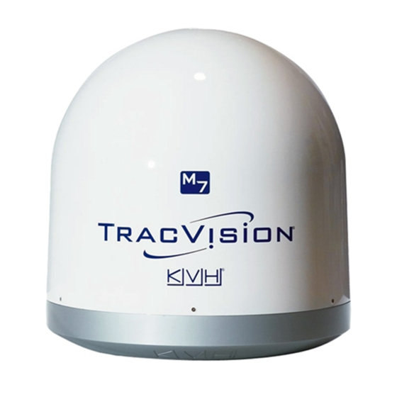
KVH Industries TracVision M7 Replacement Instructions Manual
Main pcb
Hide thumbs
Also See for TracVision M7:
- Installation manual (51 pages) ,
- Replacement instructions (4 pages) ,
- User manual (106 pages)
Advertisement
Quick Links
TracVision
M7 Main PCB Replacement
®
Instructions
The following instructions explain how to replace the main PCB in a
TracVision M7.
Tools Required
• #1 Phillips screwdriver
• #2 Phillips screwdriver
• 3/8" nut driver or wrench
• PC with the latest version of the Flash Update Wizard
installed
TIP: The Flash Update Wizard is available to KVH-authorized
dealers through the KVH Partner Portal at
partners.
For your own safety, be sure to disconnect power from all wired
components before performing this procedure.
54-0477 Rev. C
Main PCB Replacement Instructions
www.kvh.com/
CAUTION
TracVision M7
1
Advertisement

Summary of Contents for KVH Industries TracVision M7
- Page 1 TracVision M7 Main PCB Replacement Instructions TracVision M7 Main PCB Replacement ® Instructions The following instructions explain how to replace the main PCB in a TracVision M7. Tools Required • #1 Phillips screwdriver • #2 Phillips screwdriver • 3/8" nut driver or wrench •...
-
Page 2: Step 1 - Replace The Main Pcb
TracVision M7 Main PCB Replacement Instructions Step 1 - Replace the Main PCB a. Using a #2 Phillips screwdriver, remove the six #10-32 screws securing the radome. Then remove the radome and set it aside in a safe place. Figure 1 Radome Removal/PCB Cover Screws... - Page 3 TracVision M7 Main PCB Replacement Instructions d. Examine the gyro connections to the PCB. If the gyro wires are connected as shown in Figure 2 (an old version PCB is currently installed), discard the jumper cable connecting the small gyro PCB to the main PCB.
- Page 4 TracVision M7 Main PCB Replacement Instructions f. Disconnect the Molex connectors from the main PCB (see Figure 3 on page g. Using a #1 Phillips screwdriver, remove the nine screws securing the main PCB to the antenna frame (see Figure 3 on page h.
- Page 5 This procedure requires a PC with the latest version of the KVH Flash Update Wizard installed. a. Follow the instructions provided in the TracVision M7 User’s Guide to connect a PC to the TracVision system.
-
Page 6: Field Description
North America and Europe. n. Follow the instructions provided in the TracVision M7 User’s Guide to set up the TracVision system to track your selected satellites. - Page 7 TracVision M7 Main PCB Replacement Instructions Figure 5 Approximate North American Latitude and Longitude Grid # Latitude Longitude 125° W 55° N 110° W 55° N 90° W 55° N 70° W 55° N 55° W 55° N 125° W 45°...
- Page 8 TracVision M7 Main PCB Replacement Instructions Figure 6 Approximate European Latitude and Longitude Grid # Latitude Longitude 7° W 67° N 7° E 67° N 22° E 67° N 45° E 65° N 7° W 63° N 7° E 63° N 22°...
- Page 9 TracVision M7 Main PCB Replacement Instructions Step 3 - Check the RF PCB Software Version You might need to update the software in the TracVision system’s RF PCB, depending on its software version. The following instructions explain how to check the currently installed RF PCB software version.
- Page 10 PCB. Flashing also allows the antenna to use the most current satellite configuration data available. Flashing instructions vary according to specific TracVision M7 configurations. Refer to the section appropriate for your specific TracVision M7 configuration.
- Page 11 TracVision M7 Main PCB Replacement Instructions The procedure is complete! Be sure to return the old main PCB to KVH. NOTE: Before returning the main PCB, be sure to obtain an RMA number from KVH Technical Support and write the number clearly on the outside of the box.
- Page 12 TracVision M7 Main PCB Replacement Instructions MCP (MultiSat Control Panel) Configuration To flash the RF PCB, you need the special flash adapter cable supplied with the MCP. This cable is available from KVH (KVH Part # 32-0807). Figure 9 Flash Adapter Cable...
- Page 13 TracVision M7 Main PCB Replacement Instructions Flash the RF PCB a. Connect the DB9 end of the flash adapter cable to your b. Connect the stereo plug end of the flash adapter cable to the RF port on top of the MCP.


Need help?
Do you have a question about the TracVision M7 and is the answer not in the manual?
Questions and answers