Table of Contents
Advertisement
Quick Links
Advertisement
Table of Contents
Troubleshooting

Related Manuals for Oregon 730-120


Summary of Contents for Oregon 730-120
- Page 1 Original Instruction Manual Auto Chain Grinder Model 730-120 OregonProducts.com...
-
Page 2: Table Of Contents
730-120 Table of Contents 5 Operation ....24 1 Introduction ....3 5.1 Safety during operation . -
Page 3: Introduction
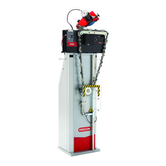
This user manual describes how to safely install, operate, and perform basic maintenance on the Oregon 730-120 Auto Chain Grinder chain sharpening machine. This manual also describes the parts of the machine, and it shows different accessories and spare parts that are available. -
Page 4: Nameplate
Introduction 730-120 1.4 Nameplate This nameplate is placed on the Oregon 730-120 Auto Chain Grinder’s grinding head. Model: 730-120 Mfg: 2016-43 Weight: 16.2kg Input: 12V DC 12A, n : 3250min 5005667 Grinding wheel suitable for 3500min Arbor: Ø .630 In (16mm) Certified to CAN/CSA-C22.2 No. -
Page 5: Safety
Safety 730-120 2 Safety 2.1 Explanation of warning levels This section contains safety information for the Oregon 730-130 Auto Chain Grinder. This manual contains WARNINGS, CAUTIONS, and NOTES that are applicable for the safe operation of the machine. DANGER Indicates a hazard with a high level of risk which, if not avoided, will result in death or serious injury. - Page 6 WARNING To prevent mistakes when chains are sharpened, it is very important to understand how the Oregon 730-120 Auto Chain Grinder works. Read the instructions carefully before operating the machine. WARNING Always wear safety gloves, protective glasses, and any other personal protective equipment suitable for your task.
-
Page 7: Signs And Symbols
CAUTION Make sure that the floor where the machine is placed is flat and level. Attach the stand to the floor with screws. 2.3 Signs and symbols See the table below for information about the signs and symbols on The Oregon 730-120 Auto Chain Grinder: Sign/Symbol Description Always wear protective glasses when using the machine. -
Page 8: Product Description
3 Product Description 3.1 Product overview The Oregon 730-120 Auto Chain Grinder is a machine that sharpens chains. The machine can sharpen 3/4" pitch chains for power saws, forestry machines, and harvesters. A pneumatic chain tensioner is attached to the stand. It secures and tensions the chain when it is sharpened. The stand has 2 chain hangers which makes it easier to separate the sharpened chains from chains that are not yet sharpened. -
Page 9: Front View
Product Description 730-120 3.2 Front view Part Description Grinding head Holds the grinding wheel in its correct position. The controls starts and stops the different functions of the Control panel machine. See section 3.6, “Controls” for further information. Chain hangers Hangers on both sides for unsharpened or sharpened chains. -
Page 10: Back View
Part Description Adjusts the pitch. Note! This wing is idle in the Pitch adjustment wing Oregon 730-120 machine. Grinding head cover and grinding Protects the grinding head and grinding wheel; it also wheel guard protects the user from sparks during grinding. -
Page 11: Grinding Head
Product Description 730-120 3.4 Grinding head The grinding wheel on the grinding head sharpens the chains. The type of wheel, the top-plate angles, the settings of the grinding head, and the profiling of the grinding wheel all determine how the chain is sharpened. -
Page 12: Pneumatic Chain Tensioner
Product Description 730-120 3.5 Pneumatic chain tensioner The purpose of the pneumatic chain tensioner is to attach and secure the chain in the correct operating position. It also keeps the chain properly tensioned during grinding. Part Description Where the tensioner slides up and down. The tensioner is Tensioner rail moved to fit chains of different lengths. -
Page 13: Controls
Product Description 730-120 3.6 Controls Part Description ON: starts the chain feed, so that the chain moves in a Chain pusher switch forward direction. OFF: stops the chain feed. Grinding speed knob Sets the grinding speed. Shuts off the power and stops the machine. The emergency... -
Page 14: Grinding Speed Knob
Product Description 730-120 3.6.1 Grinding speed knob The grinding speed knob sets the speed of the grinding wheel. The speed can be set to different speeds to grind 0" to 5/32" (0 to 4 mm) of the cutting teeth. At low speed, grinding is done in a pulsing motion. -
Page 15: Technical Data
• 5 7/8" x 5/16" x 5/8" (150 mm x 7.9 mm x 16 mm) Max dimensions for the Length (L) x Width (W) x Height (H): Oregon 730-120 Auto Chain Grinder 18.9" x 12.9" x 20.4" (480 mm x 330 mm x 520 mm) Dimensions, stand Length (L) x Width (W) x Height (H): 13.5"... -
Page 16: Installation
• pneumatic tensioner, air tubes, and 2 nipples for different types of compressors • converter (with 2 screws for assembly) • Oregon 730-120 Auto Chain Grinder User manual (this document) • rectangular profile stone (55 x 15 x 15 mm) and profile template •... -
Page 17: Assembling The Stand
730-120 4.4 Assembling the stand CAUTION The Oregon 730-120 Auto Chain Grinder machine must always be safely attached to the stand when it is used with a stand. When you use a bench, securely attach the machine to the bench. - Page 18 Installation 730-120 Start by placing the base piece on the floor. To complete the assembly of the stand, bolt Place the front piece on top of the base the side support first to the base and then piece by aligning the holes they have on the to the front piece.
-
Page 19: Assembling The Pneumatic Chain Tensioner
Installation 730-120 4.5 Assembling the pneumatic To secure the rod, start from the top. Place the provided nut on the top of the hole and chain tensioner insert the bolt from the bottom of the rod To assemble the pneumatic chain tensioner, towards the top, and then through the nut. - Page 20 Installation 730-120 There are two air lines to be attached to After the stand is assembled and secured, the pneumatic chain tensioner: one with an bolt the AC/DC converter to the back of the air fitting unit attached to the end and one stand by aligning the two holes located at without a fitting.
-
Page 21: Bench-Mounting The Machine
IMPORTANT: Although the 730-120 machine Note: For best performance, use the can be used on a bench with a chain weight, converter provided by Oregon. -
Page 22: Installing The Grinding Wheel
Installation 730-120 4.7 Installing the grinding wheel Once the grinding wheel has been verified, you’re ready to begin the install. Note: The first step in preparing the grinder for Start by removing the grinding wheel shield use is installing and centering the appropriate (C) to access the wheel attachment nut (B). -
Page 23: Test The Machine Before First Use
Installation 730-120 4.8 Test the machine before first use Next, insert the appropriate wheel onto the hub, and using moderate pressure with Make sure that all packing materials are your hands, secure the wheel attachment removed. nut to hold the wheel in place. -
Page 24: Operation
Operation 730-120 5 Operation Press the power button to turn on the machine. 5.1 Safety during operation WARNING Before you install, operate, or perform maintenance on the machine, you must read the operators manual. Obey the instructions in this manual to prevent injuries or damage to the equipment. -
Page 25: Setting The Head-Tilt Angle
Operation 730-120 5.2.2 Setting the head-tilt angle Make sure the grinding wheel edges match the shape of the chain type. Note: Read the specifications from the chain manufacturer to find out the recommended • For ceramic grinding wheels: Use the head-tilt angle for your chain. -
Page 26: Setting The Top-Plate Angle
Operation 730-120 5.2.3 Setting the top-plate angle If the top-plate angles are not the same (for example 26° in the right direction and 30° Note: Read the specifications from the chain in the left direction), adjust the nuts (A) a manufacturer to find out the recommended top- 1/2-turn at the time. - Page 27 Operation 730-120 Place the chain, with the cutter to the left of Lift the tensioner arm (there is a quick the depth gauge, into the groove on the release function) and place the chain below chain vise. the tensioner roll.
- Page 28 Operation 730-120 Move the tensioner downward until the Gently press the chain with your hand to chain is tightly secured in its position. There test the tension. The chain should not should be a gap of about 1/2" (12.7 mm) slacken.
-
Page 29: Making The Grinding Settings
Operation 730-120 5.2.5 Making the grinding settings Visually make sure that the chain pusher stops its movement exactly above the rivet CAUTION! Do not change the pitch behind the cutter, as illustrated in the image setting. The default setting is for 3/4" chains. - Page 30 Operation 730-120 Fold the grinding head down to its grinding The diameter of the grinding wheel position. decreases when it is used. To maintain the grinding proportions, the grinding The grinding depth for gullets is wheel position must be changed when the recommended by the chain manufacturer.
-
Page 31: Operating The Machine
Operation 730-120 • counterclockwise, to grind less, resulting Set the chain pusher switch to OFF when in a longer cutter top plate. the grinding head is in its uppermost position and the chain lock is not engaged. Set the chain pusher switch to ON. The... -
Page 32: Depth Gauge Grinding
Operation 730-120 Set the grinding wheel switch to ON to start Lift the tensioner arm (quick release grinding motor. function) and remove the chain. Set the chain pusher switch to ON to start the feeding of the chain and the movement of the grinding head. - Page 33 Operation 730-120 Set the top plate angle to 0°. (See 5.2.3 Change the grinding setting for the height Setting the top-plate angle) of the depth gauges. Set the depth gauge height: • Do a sharpening test on a test chain, according to the instructions in section”7.2...
- Page 34 Operation 730-120 Make the grinding settings according to the manufacturer’s recommendations. Attach the stop clamp on a tie-strap between a double-link or a joint-link. Begin grinding to the left of the stop clamp.
-
Page 35: Maintenance And Service
Maintenance and Service 730-120 6 Maintenance and Service 6.1 Safety during maintenance WARNING Make sure that the power is turned off before you install, operate, or perform maintenance on the machine. WARNING Before you install, operate, or perform maintenance on the machine, you must read the safety information in this manual. -
Page 36: Changing The Grinding Wheel And Fitting The Grinding Wheel Guard
Maintenance and Service 730-120 6.3 Changing the grinding wheel and Hold the grinding wheel and loosen the nut (B). fitting the grinding wheel guard WARNING Before a chain is sharpened, make sure that the grinding wheel is not cracked and does not vibrate or wobble. There is a simple test (called the “ring test”) that you... -
Page 37: Fastening The Chain Vise
Maintenance and Service 730-120 6.5 Checking and adjusting the wire 6.4 Fastening the chain vise Note: If the wire is not correctly set, the The chain vise needs to be fastened if the chain grinding machine will not operate correctly. -
Page 38: Service
Maintenance and Service 730-120 Set the top-plate angle to 30°. See section Set the chain pusher switch to OFF. 3, “Tighten the head-tilt angle nut.” for instructions. To set the wire so that the lifting arm meets the flange: Set the chain pusher switch to ON. -
Page 39: Troubleshooting
Troubleshooting 730-120 7 Troubleshooting 7.1 Troubleshooting procedure Make sure that the machine has sufficient power. Read section 7.4, “Issues” and section 7.5, “Troubleshooting indicators” to find a description of the issue. Perform the recommended corrective procedures. Perform a sharpening test, see instruction in section 7.2, “Sharpening test.”... -
Page 40: Issues
Troubleshooting 730-120 7.4 Issues Issues Possible cause Corrective procedure The grinding head “falls” without The wire is worn and needs to See section 6.5, “Checking and slowing down before it touches the be adjusted. adjusting the wire” cutter. The lengths of the right and left The equal cutting teeth knob is See step 13 of section 5.2.5, “Making... -
Page 41: Troubleshooting Indicators
Troubleshooting 730-120 7.5 Troubleshooting indicators Description Possible cause Corrective action The chain pusher The chain pusher motor or Contact your regional sales motor indicator shows gear is broken. representative to reach a red light and the your service team. chain pusher motor is slow or has stopped. -
Page 42: Accessories And Spare Parts
Accessories and Spare Parts 730-120 8 Accessories and Spare Parts 8.1 Ordering information Contact your local Oregon distributor or dealer to order parts and accessories. Distributor and dealer locators can be found at OregonProducts.com... -
Page 43: List Of Accessories
Accessories and Spare Parts 730-120 8.2 List of accessories Accessory Description Order Number Profile stone Stone for profiling ceramic grinding 590682 wheels. Profile template Template show how to profile the grinding 590683 wheel for different chain types. Air tension extension Shorter chains –... -
Page 44: Spare Parts
Accessories and Spare Parts 730-120 8.3 Spare parts 23 25... - Page 45 Accessories and Spare Parts 730-120 Spare Part Order Number Adjuster complete 590713 Chain lock 595283 Holder 590701 Spring 590704 Chain pusher 590703 Motor cover 590684 Turning motor 590685 Tension spring 590702 Cam curve assembly 590856 Turning motor assembly 590819 Micro switch...
- Page 46 Accessories and Spare Parts 730-120...
- Page 47 Accessories and Spare Parts 730-120 Spare Part Order Number Adjuster assembly 590720 590839 Grinding head cover 590845 Grinding wheel guard 590840 Grinding wheel centering knob assembly Grinding wheel nut 590841 Grinding wheel, see section 8.2, “List of accessories” for ordering information...
-
Page 48: Instrumental Measurements
Instrumental Measurements 730-120 9 Instrumental Measurements Code Oregon Chain Part Number Wheel Width Top-Plate Angle Head-Tilt Angle Depth Gauge 5/16" 30° 50° .070" 1.7 mm 11BC 5/16" 35° 60° .060" 1.5 mm A Measure the gauge depth using the suitable shape. -
Page 49: Warranty And Service
Warranty and Service 730-120 10 Warranty and Service Limited Warranty At Oregon, our goal is help you get the job done right with outstanding products that perform to your full satisfaction. Oregon | Blount Inc. warrants its products to be free from defects in materials and workmanship for two (2) years from the original date of purchase. - Page 50 730-120...
- Page 51 730-120...
- Page 52 Blount, Inc. 4909 SE International Way Portland, Oregon 97222 USA OregonProducts.com 585123 AA 02/17...