Table of Contents
Advertisement
Advertisement
Table of Contents

Related Manuals for Oregon 410-120


Summary of Contents for Oregon 410-120
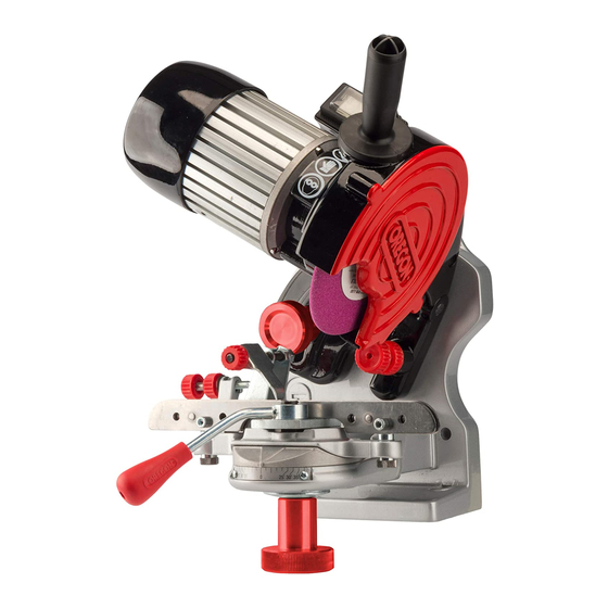
- Page 1 410-120 ORIGINAL INSTRUCTION MANUAL Bench Chain Grinder Model 410-120 MANUEL D’INSTRUCTIONS ORIGINAL Meuleuse électrique pour chaînes de scie à moteur modèle 410-120 MANUAL ORIGINAL DE INSTRUCCIONES Afiladora eléctrica para cadenas de motosierra modelo 410-120...
- Page 2 410-120 410-120 ENGLISH WARNING: READ AND UNDERSTAND ALL SAFETY WARNINGS AND ALL INSTRUCTIONS. FAILURE TO FOLLOW THE WARNINGS AND INSTRUCTIONS MAY RESULT IN ELECTRIC SHOCK, FIRE AND/OR SERIOUS INJURY. SAVE ALL WARNINGS AND INSTRUCTIONS FOR FUTURE REFERENCE. This instruction manual contains translations of a manual drafted in English and are provided to assist those who do not speak English as their first language.
-
Page 3: Table Of Contents
NAMES AND SYMBOLS TABLE OF CONTENTS NAMES AND SYMBOLS TABLE OF CONTENTS 410-120 410-120 Table of Contents NAMES AND TERMS Skilled Technician: a person who is generally employed by the service center and who is trained to carry NAMES AND TERMS ..............5 out extraordinary maintenance jobs and repairs on the machine SYMBOLS AND LABELS . -
Page 4: Safety Information
SAFETY INFORMATION SAFETY INFORMATION 410-120 410-120 SAFETY INFORMATION DON’T USE IN DANGEROUS ENVIRONMENTS USE RECOMMENDED ACCESSORIES Don’t use power tools in damp or wet locations, or Consult the operator’s manual for recommended expose them to rain Keep work area well-lighted accessories The use of improper accessories may cause risk of injury to persons Use only flanges... -
Page 5: Setting Up The Grinder
Gauges for 410-120 Grinder – Use of the machine other than that – Do not use the machine to cut or grind a grounding plug The plug must be plugged described in the “INTENDED USE”... -
Page 6: Part Description
PART DESCRIPTION PART DESCRIPTION 410-120 410-120 PART DESCRIPTION The grinder is supplied already partially assembled Upper housing / motor unit Base unit Operating handle securing bolt Operating handle securing nut Operating handle Guard securing screws (2) Shield guard Upper housing locking knob (for bench-mount only) -
Page 7: Grinding Angles Chart
GRINDING ANGLES CHART PREPARING FOR USE INSTRUMENTAL MEASUREMENTS 410-120 410-120 GRINDING ANGLES CHART PREPARING FOR USE | | ATTENTION Do not install the machine at eye level You are recommended to install it at a height of no Vise Rotate Angle... -
Page 8: Assembly
PREPARING FOR USE PREPARING FOR USE 410-120 410-120 ASSEMBLY REMOVE FLANGE REINSTALL FLANGE Using the 5 mm Allen wrench (N), remove Using the 5 mm Allen wrench (N), insert SECURING THE OPERATING HANDLE the grinding wheel flange screw (3) and the the flange (4) and tighten the screw (3) -
Page 9: Setting The Sharpening Angles
PREPARING FOR USE SETTING THE SHARPENING ANGLES 410-120 410-120 SETTING THE SHARPENING ANGLES CHECKING THE ASSEMBLY OF THE GRINDING WHEEL Stand at the side of the grinding wheel GRINDING WHEEL DRESSING Start the grinder by turning the Wear personal protection equipment switch to position “l”... -
Page 10: For Right-Hand Cutters With A Down Angle
SETTING THE SHARPENING ANGLES SETTING THE SHARPENING ANGLES 410-120 410-120 FOR RIGHT-HAND CUTTERS WITHOUT A DOWN ANGLE (0°) FOR RIGHT-HAND CUTTERS WITH A DOWN ANGLE Once you have established the type of chain to be sharpened, look up the adjustment angles This section describes how to adjust the grinder for those chain types that require a down angle setting (vise, down and head tilt angles) in the “Grinding Angles Chart”... -
Page 11: For Left-Hand Cutters Without A Down Angle (0°)
SETTING THE SHARPENING ANGLES SETTING THE SHARPENING ANGLES 410-120 410-120 FOR LEFT-HAND CUTTERS WITHOUT A DOWN ANGLE (0°) SETTING THE HEAD TILT ANGLE Loosen the locking knob (H) at the Once you have established the type of chain to be sharpened, look up the adjustment angles back of the motor unit (A) (vise, down and head tilt angles) in the “Grinding Angles Chart”... -
Page 12: For Left-Hand Cutters With A Down Angle
SETTING THE SHARPENING ANGLES SETTING THE SHARPENING ANGLES 410-120 410-120 FOR LEFT-HAND CUTTERS WITH A DOWN ANGLE SETTING THE HEAD TILT ANGLE Loosen the locking knob (H) at the This section describes how to adjust the grinder for those chain types that require a down angle back of the motor unit (A) setting To find out which chains require this setting, consult column B in the chain chart on page 12... -
Page 13: Placing The Chain In The Vise
PLACING THE CHAIN IN THE VISE PLACING THE CHAIN IN THE VISE 410-120 410-120 PLACING THE CHAIN IN THE VISE Raise the motor unit (A) using handle (E) Turn cutter sharpening depth adjustment knob (5) to adjust the cutter sharpening depth The grinding wheel (K) should skim –... -
Page 14: Operating Instructions
OPERATING INSTRUCTIONS OPERATING INSTRUCTIONS 410-120 410-120 OPERATING INSTRUCTIONS Once you have sharpened the first cutter, Clamp chain again with the vise handle (13) raise the motor unit with handle (E) and sharpen the next cutter SHARPENING THE CHAIN – Wear personal protection equipment –... -
Page 15: Grinding Wheel Dressing For Setting The Depth Gauge
OPERATING INSTRUCTIONS OPERATING INSTRUCTIONS 410-120 410-120 Raise the motor unit (A) with handle (E) Stop the grinder by turning the switch to position “O” and remove the dressing brick (O) from the vise GRINDING WHEEL DRESSING FOR SETTING THE DEPTH GAUGE Fit the 1/4"... -
Page 16: Stopping And Shutting Down
STOPPING, MAINTENANCE, DISPOSAL WARRANTY AND SERVICE 410-120 410-120 STOPPING AND SHUTTING DOWN WARRANTY AND SERVICE The warranty validity is that acknowledged in the country of sale Claims STOPPING SHUTTING DOWN under warranty will only be accepted if they are backed up by the copy of the Turn the machine off by turning the Once you have finished using the machine,... -
Page 17: Troubleshooting
TROUBLESHOOTING 410-120 410-120 TROUBLESHOOTING Turn the machine off by turning the switch to position “0” and unplug the power cable from the mains before you start to work on the machine Problem Probable Cause Solution The machine fails to start... -
Page 18: Illustrated Parts List
ILLUSTRATED PARTS LIST ILLUSTRATED PARTS LIST 410-120 410-120 ILLUSTRATED PARTS LIST DESCRIPTION 572119 Complete vise assembly 537411 Chain stop vise assembly 522688 Chain stop 32677 Chain stop (5 pack) 32681 Pawl center spring kit (5 pack) 572522 Adjustment knobs kit...
Need help?
Do you have a question about the 410-120 and is the answer not in the manual?
Questions and answers