Table of Contents

Subscribe to Our Youtube Channel
Related Manuals for Tractel supertirfor TU-16H


Summary of Contents for Tractel supertirfor TU-16H
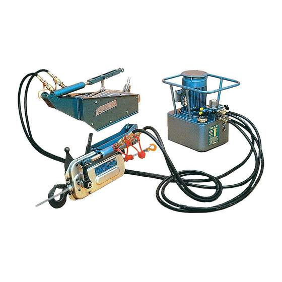
- Page 1 ® supertirfor motorised lifting and pulling machines models TU-16H TU-32H HYDRAULIC POWER PACKS 1, 2 or 4 way operation operating and equipment in maintenance accordance with instructions CE directives 106925-03 - ind 01 - 09/02 ® ®...
-
Page 2: Table Of Contents
TRACTEL Group reserves the right to modify the specifications of the equipment described in this manual. The companies of the TRACTEL Group and their agents or distributors will supply on request descriptive documentation on the full range of... -
Page 3: Technical Data
ON, then OFF. The motor should rotate clockwise. (See section 3.3.1 on page 7.) LIFTING PEOPLE AND SPECIAL APPLICATIONS For further information on equipment for lifting people, and for any special application, please refer to TRACTEL TECHNICAL DATA ®... -
Page 4: Description Of Equipment
1. DESCRIPTION OF EQUIPMENT independently of the pressure or length of the hoses on each ram. ® 1.1. SUPERTIRFOR 1.2.4 Standard set of equipment ® The SUPERTIRFOR machine is a power-operated A standard set of equipment comprises : lifting and pulling machine. It is versatile, portable •... - Page 5 For any rigging arrangement other than those described in this manual, please consult N.B. : Whatever the rigging arrangement, and if TRACTEL or a competent specialist the machine is anchored to a fixed point, ensure engineer before operating the machine.
-
Page 6: Installation
3. INSTALLATION A click may be heard when the anchor pin is correctly locked into position. Ensure that the ® 3.1. SUPERTIRFOR machines anchor pins are well lubricated. 3.1.1 TU16H 3.1.2. TU32H 1. If not already fitted, mount the anchor bracket Mount the VA3 ram onto the TU32H fitted with its onto the machine. - Page 7 1. Check that the machine is not connected to the 3.3. Hydraulic power pack mains power supply. NOTE : The following operations should preferably 2. Open the electric control box, using an 8mm flat be carried out at the factory before going to site. or tube spanner to unscrew the 4 hexagonal N.B.
-
Page 8: Releasing And Engaging The Jaws
4. Open the flow regulator D fully (ON position) and 2. Release the safety catch and continue to lift the put the lever(s) to the open position (with the rope release lever until it locks into position. The lever pointing upwards). internal mechanism is in the released position. -
Page 9: Anchoring
Engaging : It is recommended that SUPERTIRFOR ® machines 1. Push the rope release lever towards the anchor should be anchored to a fixed point or to the load point. using an appropriate capacity sling. It is 2. Press and maintain pressure on the rope release forbidden to use the machine’s wire rope as a safety catch, allowing the release lever to slowly sling by passing it around the load and hooking it... -
Page 10: Operation
Fig. 17 - Anchor pin in position Fig. 18 - Anchor pin removed Fig. 19 - Spring clip closed Fig. 20 - Spring clip open Warning : It is essential for the safe To anchor using the anchor pin, follow the operation of the machine to ensure that, before procedure below: loading the machine, the anchor points, hooks or... -
Page 11: Taking Out Of Service And Storage
Hydraulic power pack with petrol engine : 7. TAKING OUT OF SERVICE AND STORAGE Start the engine (see description in paragraph Stop the hydraulic power pack. Open the flow 3.3.2) refering to the instruction manual of the regulator and the separate operating levers on engine manufacturer. -
Page 12: Safety Devices
8. SAFETY DEVICES 9. REPLACING THE SHEAR PINS Figures 22 and 23 show the position of the shear ® 8.1. SUPERTIRFOR machines pins for the various models. Spare shear pins are 8.1.1 Overload limiting safety devices in the stub of the forward operating lever for the All machines incorporate a shear pin system. -
Page 13: Wire Rope
Before putting the machine back into operation, ensure that the cause of the overload is removed. If necessary, use multiple sheave blocks (See Fig. 6). Remember to re-order spare shear pins and put them back in the correct place. 10. WIRE ROPE Fig. -
Page 14: Maintenance Instructions
Check that the drain screw is correctly fitted before The machine should be inspected, cleaned and refilling the reservoir with hydraulic fluid. lubricated at regular intervals, at least annually, by an approved TRACTEL repairer. Never use grease or oil containing graphite WARNINGS AGAINST HAZARDOUS additives or molybdenum disulphide. -
Page 15: Troubleshooting
Should this not be possible, - Never obstruct the machine, which could prevent return the machine and wire rope to a TRACTEL the machine, the wire rope and the anchor approved repairer.
Need help?
Do you have a question about the supertirfor TU-16H and is the answer not in the manual?
Questions and answers