
Related Manuals for Canon Inner Finisher-D1


Summary of Contents for Canon Inner Finisher-D1
- Page 1 ENGLISH 日本語 Finisher-D1 with Inner 2/3 Hole Puncher-A1 Installation Procedure Follow the instructions herein when installing the equipment to its host machine. PRINTED IN CHINA PUB No. FT1-0627-000 ENGLISH 日本語...
- Page 2 Inner Finisher-D1 and Inner 2H Puncher-A1 A symbol is described on the illustration in the case of using the parts included in the package of this product. Inner Finisher-D1 with Inner 2/3 Hole Puncher-A1 F-1-1 Symbols in the Illustration 500 mm or more...
- Page 3 Additional Tray-A1 prior to the installation of the Inner Finisher-C1.Refer to the installation procedure of the Additional Tray-A1 . 1. When the Additional Tray-A1 is installed to the Inner Finisher-D1, install the Additional Tray-A1 prior to the installation of the Inner Finisher-D1. Refer to the installation procedure of the Additional Tray-A1.
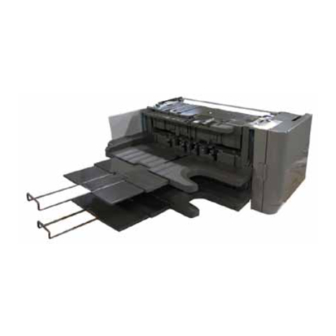
- Page 4 Checking the Contents > Included Items of Inner Finisher-D1 with Inner 2/3 Hole Puncher-A1 Checking the Contents Unpack the Inner Finisher-D1 with Inner 2/3 Hole Puncher-A1 and make sure that none of the following parts is missing. Included Items of Inner Finisher-D1 with Inner 2/3 Hole Puncher-A1 Inner Finisher 1 pc.
- Page 5 Installation Procedure > Preparation at the Host Machine Installation Procedure 3) Remove the support cover. • 2 screws Preparation at the Host Machine • 2 hooks 1) Open the right cover of the host machine. 2) Open the delivery guide. •...
- Page 6 Installation Procedure > Preparation at the Host Machine 5) Open the front cover of the host machine. 8) Remove the delivery rear cover (upper/lower) and the delivery tray. 6) Open the toner supply cover. (Removed delivery rear covers, delivery tray and screws are no longer reused.) •...
- Page 7 Installation Procedure > Preparation at the Host Machine 10)Lift up the sensor flag (for the delivery tray 1 full detection) as shown in the figure and 12) Remove the sensor flag (for the delivery tray 2 full detection) if there is. remove it.
- Page 8 Installation Procedure > Installing the Punch Unit in the Host Machine Installing the Punch Unit in the Host Machine 4) Remove the sliding fixture. (Removed sliding fixture and screws are no longer reused.) • 2 screws 1) Hold the parts as instructed in the fi gure and take the punch unit out of the carton box. F-1-15 F-1-17 2) Remove all the shipping tapes and the packing materials for transport.
- Page 9 Installation Procedure > Installing the Punch Unit in the Host Machine 6) Hold the parts as instructed in the fi gure and set the punch unit in the host machine. 7) Fix the punch unit to the host machine. • 1 screw (RS Tightening; M3x8) CAUTION: Pay attention that the punch cable harness should not be caught in hardwareand release the harness towards the main power switch.
- Page 10 Installation Procedure > Installing the Inner Finisher in the Host Machine Installing the Inner Finisher in the Host Machine 9) Attach the eddge saddle at frame edge as shown and put the punch cable harness in the saddle. 1)Fix the rail unit •...
- Page 11 Installation Procedure > Installing the Inner Finisher in the Host Machine 2) Manipulate the left cover of the host machine and fix the tray lower cover. 5) Move the finisher mount of the rail unit to the left till it stops. •...
- Page 12 Installation Procedure > Installing the Inner Finisher in the Host Machine NOTE: 6) Hold the inner finisher as shown in the figure and take it out of the carton. It is good way for the preparation to place a packing material, etc. under the inner finisher and hold it horizontal.
- Page 13 Installation Procedure > Installing the Inner Finisher in the Host Machine 7) Remove the metal fixtures, all the shipping tapes and the cushioning materials. 8) Hold the inner finisher as shown in the figure and set it on the rail unit. Slowly push in the (All the removed parts and screws are no longer reused.) finisher to the host machine till it stops so that the triangle mark of the finisher aligns with the left edge of the reader unit.
- Page 14 Installation Procedure > Installing the Inner Finisher in the Host Machine 9) Fix the finisher at front. 11)In the case the additional tray (option) has been installed, follow the procedure below or • 1 screw (RS Tightening; M3x8) proceed to the next step if not. Go to the rear side and remove 2 screws from the additional tray drive.
- Page 15 Installation Procedure > Installing the Inner Finisher in the Host Machine 12) Attach the joint arm of the punch unit to the inner finisher. Joint 3 connectors of the punch 13) Fix the cable cover included in the inner puncher carton together with the joint arm. Pay relay cable to the joint arm.
- Page 16 Installation Procedure > Installing the Inner Finisher in the Host Machine 14) Store the relay harness and switch harness of the host machine in the wire saddle of the 16) Joint 2 connectors of the punch relay harness to the relay harness of the host machine cover hinge mount included in the inner puncher carton.
- Page 17 Installation Procedure > Installing the Inner Finisher in the Host Machine 18) Restore the support cover. 20) Open the ADF (or the copy board cover) and remove the reader front cover. • 2 screws (RS tightening; M3x6, removed at step 3) of “Preparation at the Host Machine”) •...
- Page 18 Installation Procedure > Installing the Inner Finisher in the Host Machine 21) Remove 2 screws to remove the blindfold cover from the reader front cover. 22) Restore the reader front cover Using removed 2 screws, fix the operation sub cover. •...
- Page 19 Others > For Support Guide Check After Installation Others Operation Check For Support Guide The support guide is put away in the reverse side of the tray. Though it is no need to use the support guide usually, the two effects described in the next page are expected by attaching 1) Plug in the host machine and turn the main power switch ON.
- Page 20 Others > For Support Guide 1.Not installing the support guide 3.Installing the tip of the support guide upward - Normal how to use -When a sufficient effect is not obtained by the above step 2. F-1-49 2.Installing the tip of the support guide downward F-1-51 -It is effective in prevention of a fall of the curled paper.
Need help?
Do you have a question about the Inner Finisher-D1 and is the answer not in the manual?
Questions and answers