
Related Manuals for WIKA CPB 5000


Summary of Contents for WIKA CPB 5000
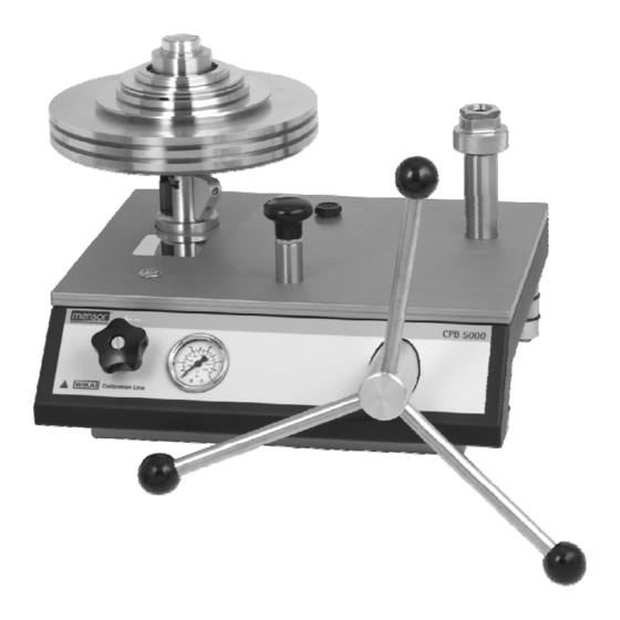
- Page 1 Operating Instructions Betriebsanleitung Pressure Balance Kolbenmanometer CPB 5000 Pressure Balance CPB 5000...
- Page 2 Betriebsanleitung Kolbenmanometer Seite 40 - 77 Information This symbol provides you with information, notes and tips. Warning! This symbol warns you against actions that can cause injury to people or damage to the instrument. WIKA Operating Instructions Pressure Balance Version 3.1...
-
Page 3: Table Of Contents
3.2.6 Releasing pressure – hydraulic , pneumatic and vacuum ..........25 3.3 Disassembly ..........................26 4. Troubleshooting measures ....................27 5. Maintenance and Care ....................28 WIKA Operating Instructions Pressure Balance Version 3.1... - Page 4 ....................34 7. Tables of masses ....................37 7.1 Hydraulic models ........................37 7.2 Pneumatic models ........................38 8. Accessories ....................39 WIKA Operating Instructions Pressure Balance Version 3.1...
-
Page 5: General
1. General 1.1 General Instructions In the following chapters detailed information on the CPB 5000 pressure balance and its proper use can be found. Should you require further information, or should there be problems which are not dealt within detail in the operating instructions, please contact the address below: WIKA Alexander Wiegand SE &... -
Page 6: Safety Instructions
"Setting up the device" are taken into consideration. 3. The CPB 5000 always has to be handled with the care required for an precision instrument (protect from humidity, impacts and extreme temperatures). The device, the piston-cylinder-system and the mass-set must be handled with care (don't throw, hit, etc.) and protect them from contamination. -
Page 7: Product Description
Piston/cylinder measuring system Pressure is defined as a quotient of force and area. Correspondingly, the core of the CPB 5000 is a very precisely manufactured piston/cylinder system. Both the piston and cylinder are manufactured from Tungsten Carbide and are very well protected in a solid stainless steel housing against touching, impacts or contamination from outside. -
Page 8: Basic Principle Of The Pressure Balance
Local gravity set during manufacturing: 9.806650 m/s Locale gravity at application site: 9.811053 m/s Nominal pressure: 100 bar 81105 Local 0449 True pressure: Nominal 80665 dard Without the correction, measurements would all be "off" by 0.05 %. WIKA Operating Instructions Pressure Balance Version 3.1... -
Page 9: Temperature (Piston/Cylinder)
The air density is typically 1.2 kg/m The density of the weights (non-magnetic steel) is 7900 kg/m A fluctuation of 5% in the relative humidity causes an additional uncertainty in the measurement of about 0.001%. WIKA Operating Instructions Pressure Balance Version 3.1... -
Page 10: How The Cross-Sectional Surface Responds To Pressure
1000 Without the correction, measurements would all be "off" by 0.01 %. 2.4 Arrangement of control elements The CPB 5000 instrument bases are available in the 4 following versions, which vary in the arrangement of the control elements Pneumatic low-pressure base... -
Page 11: Pneumatic Low-Pressure Base
Test pressure gauge Outlet valve Rear view Interface to CPU 5000 (in combination with CPU 5000 only) Interface to the external piston temperature sensor (optional and in combination with CPU 5000 only) Rotating base WIKA Operating Instructions Pressure Balance Version 3.1... -
Page 12: Pneumatic High-Pressure / Vacuum Base
Rear view (in combination with CPU 5000 only) Interface to the external piston temperature sensor (optional and in combination with Connection for CPU 5000 only) external pressure supply or vacuum source Rotating base WIKA Operating Instructions Pressure Balance Version 3.1... -
Page 13: Hydraulic Base
1200 bar) Outlet valve Rear view Interface to CPU 5000 (in combination with CPU 5000 only) Interface to the external piston temperature sensor (optional and in combination with CPU 5000 only) Rotating base WIKA Operating Instructions Pressure Balance Version 3.1... -
Page 14: Commissioning And Operation
In the pneumatic version with integrated gas to oil separator, an external compressed air supply has to be connected. ® The pressure connection is specified as SWAGELOK pipe connection with an outside pipe diameter of 6 mm at the back of the instrument base. WIKA Operating Instructions Pressure Balance Version 3.1... -
Page 15: Instructions For Hydraulic Version
5.3.3. The protection film on the screwed drain plug of the oil container need to be removed before operating in the hydraulic design (coverage of the ventilation hole during transportation). WIKA Operating Instructions Pressure Balance Version 3.1... -
Page 16: Installing The Contect System
For an exact alignment of the device, the water level may be removed from the basement plate and placed on the top of the clamped piston/cylinder system. This will ensure the most accurate referencing of the piston/cylinder system. Here put on water level O-ring (see accessories section 8.) WIKA Operating Instructions Pressure Balance Version 3.1... -
Page 17: Connection For Piston/Cylinder System With Contect Quick Connector
This will ensure the most accurate referencing of the piston/cylinder system. Here put on water level O-ring 4 x 2.2 (see accessories section 8.) WIKA Operating Instructions Pressure Balance Version 3.1... -
Page 18: Vacuum Piston/Cylinder System
For an exact alignment of the device, the water level may be removed from the basement plate and placed on the top of the clamped piston/cylinder system. This will ensure the most accurate referencing of the piston/cylinder system. (step 5) Here put on water level WIKA Operating Instructions Pressure Balance Version 3.1... -
Page 19: Connection For Piston/Cylinder System With Integrated Separator, M30 X 2 Female Thread
For an exact alignment of the device, the water level may be removed from the basement plate and placed on the top of the clamped piston/cylinder system. This will ensure the most accurate referencing of the piston/cylinder system. Here put on O-ring water level (see accessories section 8.) WIKA Operating Instructions Pressure Balance Version 3.1... -
Page 20: Connecting The Test Specimen
Open the outlet valve, any trapped air will escape into the tank This procedure may need to be repeated 1 to 2 times in order to remove all trapped air. The device is now ready to use. WIKA Operating Instructions Pressure Balance Version 3.1... -
Page 21: Operation
The pressure that will be achieved thus corresponds to the sum of the basic weight (piston), the bell and the weight rings. To reduce the starting value, the weight plate (No. 2) can be used as the basic holding surface instead of the bell (No. 1). WIKA Operating Instructions Pressure Balance Version 3.1... -
Page 22: Approaching The Pressure Value - Hydraulic Base
The maximum permissible pressure for the pneumatic low-pressure version is 10 bar. Higher pressures may damage the instrument. The piston/cylinder system, test specimen and any connecting tubes that are used must not be subjected to pressures above the maximum permissible level. WIKA Operating Instructions Pressure Balance Version 3.1... -
Page 23: Approaching The Pressure Value - Pneumatic High-Pressure / Vacuum Base
This state is easy to identify with the aid of the level indicator and mirror. In this case the lower edge of the bell must stay at the position of the marking line of the piston/cylinder system. Marking line for float Lower edge of the position bell Mirror WIKA Operating Instructions Pressure Balance Version 3.1... -
Page 24: Next Pressure Level
180°, this means oppositely positioned. WIKA Operating Instructions Pressure Balance Version 3.1... -
Page 25: Approaching The Vacuum Values
To release pressure more quickly or for venting, the fine adjustment valve (outlet valve) can also be carefully opened. Attention: In this case the piston must stay in the lower position! Caution: The piston is lowered very quickly just before equilibrium is achieved. WIKA Operating Instructions Pressure Balance Version 3.1... -
Page 26: Disassembly
Spring-loaded thrust pad For transportation of the pneumatic version with integrated gas to oil separator the oil should be removed from the separator free of residues, see section 3.1.1.2. WIKA Operating Instructions Pressure Balance Version 3.1... -
Page 27: Troubleshooting Measures
Doing so could cause lasting damage that would seriously affect measurement properties. The piston must be cleaned (see section 5.1.1) Further help can be found through WIKA's Calibration Technology Department. WIKA Operating Instructions Pressure Balance Version 3.1... -
Page 28: Maintenance And Care
Now the piston can be drawn slowly and carefully out of the cylinder, removing it vertically upward. The best way to do this is set the piston/cylinder unit down on a plate and keeps it still. Unscrew the union nut The cylinder can be removed out of the housing WIKA Operating Instructions Pressure Balance Version 3.1... - Page 29 "fall" into the cylinder by its own weight. Tighten the knurled nut again Never press the piston forcibly into the cylinder. Otherwise it is damaged. The system is now ready to use again. WIKA Operating Instructions Pressure Balance Version 3.1...
-
Page 30: Pneumatic Piston/Cylinder System
For this we recommend the use of the cleaning-set for piston/cylinder systems, which is available as an accessory (see section 8. Accessories). It contains a detailed operating instruction for the cleaning process. WIKA Operating Instructions Pressure Balance Version 3.1... -
Page 31: Weight Set
Accessories, section 8). Important: Use original seals only. Seals having deviant measurements, or materials, or material grades, may cause damage to the device and test specimen, and pose a danger for the operator. WIKA Operating Instructions Pressure Balance Version 3.1... -
Page 32: Changing The Hydraulic Oil (Hydraulic Design Only)
The initial pressure pump must be actuated until air bubbles no longer appear. Any oil escaping in the open piston/cylinder system and test specimen connections should be siphoned off, for example, with a nozzle. WIKA Operating Instructions Pressure Balance Version 3.1... -
Page 33: Recalibration
For recalibration or if you have questions about the optimal recalibration cycle, the DKD lab would be happy to assist you: WIKA Alexander Wiegand SE & Co. KG DKD-Kalibrierlaboratorium Alexander-Wiegand-Strasse 63911 Klingenberg / Germany... -
Page 34: Specifications
The accuracy is in reference to the measurement value, from 10% of the measurement range. A fixed error is considered in the lower area in reference to 10% of the area. Measurement uncertainty assuming reference conditions (room temperature 20°C, air pressure 1013 mbar, relative humidity 40 %). Corrections may be required for use without CalibratorUnit. Other on request. WIKA Operating Instructions Pressure Balance Version 3.1... - Page 35 (depending on measuring range) Mass-set manufactured to standard gravity (9.80665 m/s²) Operating fluid 1 litre (only for hydraulic version) resp. 0.25 litre (for separator version) Operating instructions in German and English Factory calibration certificate WIKA Operating Instructions Pressure Balance Version 3.1...
- Page 36 CPB 5000 Dimensions The drawing shows a pneumatic high-pressure base CPB5000 including the ConTect quick connector available as an option. The pneumatic low-pressure version and the hydraulic version do not vary in their dimensions. WIKA Operating Instructions Pressure Balance Version 3.1...
-
Page 37: Tables Of Masses
14.5 Bell jar 23.1 115.5 Aluminium plate Mass 3.5 kg 1000 1000 Mass 1.4 kg Mass 1 kg Mass 0.7 kg Mass 0.35 kg Mass 0.175 kg Mass 0.14 kg Mass 0.07 kg WIKA Operating Instructions Pressure Balance Version 3.1... -
Page 38: Pneumatic Models
Mass 0.7 kg Mass 0.35 kg Mass 0.19 kg 0.548 2.74 13.7 13.7 13.7 Mass 0.175 kg Mass 0.14 kg Mass 0.12 kg 0.345 1.725 8.625 8.625 8.625 Mass 0.07 kg Mass 0.035 kg WIKA Operating Instructions Pressure Balance Version 3.1... -
Page 39: Accessories
Cleaning set for ConTect-systems, pneumatic version 12485943 Cleaning set for ConTect-systems, hydraulic version 12481425 Special test item connection with quick-connector, for adaptation into 2152634 the fixture for the ConTect-System, operation as comparison test pump possible WIKA Operating Instructions Pressure Balance Version 3.1... - Page 40 Kolbenmanometer CPB 5000 Information Dieses Zeichen gibt Ihnen Informationen, Hinweise oder Tipps. Warnung! Dieses Symbol warnt Sie vor Handlungen, die Schäden an Personen oder am Gerät verursachen können. WIKA Betriebsanleitung Kolbenmanometer Version 3.1...
- Page 41 3.2.6 Druck entlasten – Hydraulik, Pneumatik und Vakuum ............63 3.3 Abbau ............................64 4. Maßnahmen bei Störungen ....................... 65 5. Pflege und Wartung ....................... 66 WIKA Betriebsanleitung Kolbenmanometer Version 3.1...
- Page 42 6. Technische Daten ....................... 72 7. Gewichtstabellen ....................... 75 7.1 Hydraulische Modelle ........................ 75 7.2 Pneumatische Modelle ......................76 8. Zubehör ....................... 77 WIKA Betriebsanleitung Kolbenmanometer Version 3.1...
-
Page 43: Allgemeines
1. Allgemeines 1.1 Allgemeine Hinweise In den folgenden Kapiteln erhalten Sie nähere Informationen zum Kolbenmanometer CPB 5000 und seinen ordnungsgemäßen Einsatz. Sollten Sie weitere Informationen wünschen, oder treten besondere Probleme auf, die in der Betriebsanleitung nicht ausführlich behandelt werden, erhalten Sie Auskunft unter folgender Adresse: WIKA Alexander Wiegand SE &... -
Page 44: Sicherheitshinweise
2. Die einwandfreie Funktion und Betriebssicherheit des Gerätes kann nur unter Berücksichtigung der im Kapitel "Aufstellung des Gerätes“ beschriebenen Bedingungen eingehalten werden. 3. Das CPB 5000 ist stets mit der für ein Präzisionsgerät erforderlichen Sorgfalt zu behandeln (vor Nässe, Stößen und extremen Temperaturen schützen). Gerät, Kolben-Zylinder-System und Massensatz müssen pfleglich behandelt werden (nicht werfen, aufschlagen, etc.) und sind vor... -
Page 45: Produktbeschreibung
Einsatz vor Ort, in der Wartung und im Service geeignet. Kolben-Zylinder Messsystem Druck ist definiert als der Quotient aus Kraft und Fläche. Das Herzstück des CPB 5000 bildet dementsprechend ein sehr präzise gefertigtes Kolben-Zylinder-System. Sowohl der Kolben, als auch der Zylinder sind aus Wolfram Carbid gefertigt und in einem massiven Gehäuse aus Edelstahl sehr gut geschützt gegen Berührung, Stöße oder Verschmutzung von außen. -
Page 46: Grundprinzip Kolbenmanometer
Norm Beispiel: Lokaler Schwerewert bei der Herstellung: 9,806650 m/s Lokaler Schwerewert am Einsatzort: 9,811053 m/s Nominal-Druck: 100 bar 81105 lokal 0449 Wahrer Druck: Nominal 80665 Norm Ohne Korrektur würde um 0,05 % „falsch“ gemessen werden. WIKA Betriebsanleitung Kolbenmanometer Version 3.1... -
Page 47: Temperatur (Kolben-Zylinder)
⎟ Masse Nominalmas ⎝ ⎠ Massendich Die Luftdichte ist typischerweise 1,2 kg/m Die Dichte der Massen (nichtmagnetischer Stahl): 7900 kg/m Aus einer Schwankung der Luftdichte um 5% ergibt sich eine zusätzliche Messunsicherheit von ca. 0,001%. WIKA Betriebsanleitung Kolbenmanometer Version 3.1... -
Page 48: Druckabhängigkeit Der Querschnittsfläche
1000 Ohne Korrektur würde um 0,01 % „falsch“ gemessen werden. 2.4 Anordnung der Bedienelemente Die CPB 5000 Basisgeräte sind in folgenden 4 Ausführungen erhältlich, die sich in der Anordnung der Bedienelemente unterscheiden: Basement pneumatisch Niederdruck - bis max. 10 bar / 150 psi - mit integrierter Druckerzeugung über Vordruckpumpe und Spindelpumpe... -
Page 49: Basement Pneumatisch Niederdruck
System Libelle Vordruckpumpe Spindelpumpe Frontansicht Prüfdruck- Manometer Auslass- Ventil Rückansicht Schnittstelle zur CPU 5000 (nur in Kombination mit CPU 5000) Schnittstelle zum externen Kolben- Temperaturfühler (optional und nur in Kombination mit CPU 5000) drehbare Füße WIKA Betriebsanleitung Kolbenmanometer Version 3.1... -
Page 50: Basement Pneumatisch Hochdruck / Vakuum
Ventil Ventil Rückansicht Schnittstelle zur CPU 5000 (nur in Kombination mit CPU 5000) Schnittstelle zum externen Kolben- Temperaturfühler (optional und nur in Kombination mit Anschluss für CPU 5000) externe Druck- versorgung oder drehbare Füße Vakuumquelle WIKA Betriebsanleitung Kolbenmanometer Version 3.1... -
Page 51: Basement Hydraulisch
Prüfdruckmanometer Frontansicht (nicht bei Sonderausführung 1200 bar) Auslass- Ventil Rückansicht Schnittstelle zur CPU 5000 (nur in Kombination mit CPU 5000) Schnittstelle zum externen Kolben- Temperaturfühler (optional und nur in Kombination mit CPU 5000) drehbare Füße WIKA Betriebsanleitung Kolbenmanometer Version 3.1... -
Page 52: Inbetriebnahme Und Betrieb
3.1.1.2 Hinweise zur Geräteausführung „pneumatisch mit integrierter Trennvorlage Luft auf Öl“ In der Ausführung pneumatisch mit integrierter Trennvorlage „Luft auf Öl“ muss eine externe Druckluftversorgung angeschlossen werden. ® Der Druckanschluss ist als SWAGELOK - Rohrverbindung mit 6 mm Rohraußendurchmesser an der Geräterückseite ausgeführt. WIKA Betriebsanleitung Kolbenmanometer Version 3.1... -
Page 53: Hinweise Zur Geräteausführung „Hydraulisch
Zubehör erhältlich). Bei Erstbefüllung oder nach einem kompletten Austausch des Öls ist das System zu entlüften. Hierzu ist nach Pkt. 5.3.3 vorzugehen. In der Hydraulik-Ausführung ist vor dem Betrieb die Schutzfolie der Verschlussschraube am Ölbehälter zu entfernen (Abdeckung der Belüftungsbohrung für Transport). WIKA Betriebsanleitung Kolbenmanometer Version 3.1... -
Page 54: Einbau Des Kolben-Zylinder-Systems
Zum exakten Ausrichten des Gerätes kann die Libelle aus der Basisplatte herausgenommen werden und auf die Oberseite des eingespannten Kolben-Zylinder-Systems aufgelegt werden. Hierdurch ist die genaueste Referenzierung zum Kolben-Zylinder-System gegeben. Libelle auflegen O-Ring (siehe Zubehör Pkt. 8.) WIKA Betriebsanleitung Kolbenmanometer Version 3.1... -
Page 55: Kolbenaufnahme Mit Contect-Schnellverschluss
Zum exakten Ausrichten des Gerätes kann die Libelle aus der Basisplatte herausgenommen werden und auf die Oberseite des eingespannten Kolben-Zylinder-Systems aufgelegt werden. Hierdurch ist die genaueste Referenzierung zum Kolben-Zylinder-System gegeben. Libelle auflegen O-Ring 4 x 2,2 (siehe Zubehör Pkt. 8.) WIKA Betriebsanleitung Kolbenmanometer Version 3.1... -
Page 56: Vakuum Kolben-Zylinder-System
(Schritt 4) Zum exakten Ausrichten des Gerätes kann die Libelle aus der Basisplatte herausgenommen werden und auf die Oberseite des eingespannten Kolben-Zylinder-Systems aufgelegt werden. Hierdurch ist die genaueste Referenzierung zum Kolben-Zylinder-System gegeben. (Schritt 5) Libelle auflegen WIKA Betriebsanleitung Kolbenmanometer Version 3.1... -
Page 57: Kolbenaufnahme Mit Integrierter Trennvorlage Mit M30 X 2 Innengewinde
Zum exakten Ausrichten des Gerätes kann die Libelle aus der Basisplatte herausgenommen werden und auf die Oberseite des eingespannten Kolben-Zylinder-Systems aufgelegt werden. Hierdurch ist die genaueste Referenzierung zum Kolben-Zylinder-System gegeben. Libelle auflegen O-Ring (siehe Zubehör Pkt. 8.) WIKA Betriebsanleitung Kolbenmanometer Version 3.1... -
Page 58: Anschluss Des Prüflings
Wichtig: Das Kolben-Zylinder-System muss hierbei in seiner unteren Position bleiben, also noch nicht in den Schwebezustand gehen. Auslassventil öffnen, vorhandene Lufteinschlüsse entweichen in den Tank Gegebenenfalls ist dieser Vorgang 1-2 mal zu wiederholen, um sämtliche Lufteinschlüsse zu entfernen. Das Gerät ist nun einsatzbereit WIKA Betriebsanleitung Kolbenmanometer Version 3.1... -
Page 59: Betrieb
1013 mbar, relative Luftfeuchte 40 %) Der sich einstellende Druck entspricht dann der Summe aus der Grundlast (Kolben), Glocke sowie Masseringe. Zur Verringerung des Startwertes, kann statt der Glocke (Nr. 1), der Masseteller (Nr. 2) als Grundauflage eingesetzt werden WIKA Betriebsanleitung Kolbenmanometer Version 3.1... -
Page 60: Druckwert Anfahren - Basement Hydraulisch
Mit Hilfe der Spindelpumpe kann in der Nähe des Druckwertes eine Feineinstellung vorgenommen werden. Der zulässige Betriebsdruck beträgt bei der Ausführung pneumatisch Niederdruck maximal 10 bar. Größere Drücke können das Gerät beschädigen. Kolben-Zylinder-System, Prüfling und evtl. eingesetzte Verbindungsschläuche dürfen nicht durch unzulässig hohen Druck überlastet werden. WIKA Betriebsanleitung Kolbenmanometer Version 3.1... -
Page 61: Druckwert Anfahren - Basement Pneumatisch Hochdruck / Vakuum
So lange Druck einlassen, bis sich das System im Gleichgewichtszustand befindet. Dieser Zustand kann mit Hilfe des Spiegels sehr gut abgelesen werden. Der Glockenunterrand muss in diesem Fall an der Markierungslinie des Kolben-Zylinder-Systems anliegen. Markierungslinie für Glockenunterrand Schwebezustand Spiegel WIKA Betriebsanleitung Kolbenmanometer Version 3.1... -
Page 62: Nächste Druckstufe
Der Zentrierbund an der Scheibe zeigt hierbei nach unten. Je nach angestrebten Druckwert, werden die weiteren Massenscheiben aufgelegt. Beim Aufeinanderstapeln der Scheiben ist darauf zu achten, dass die Öffnungen der Scheiben stets ca. 180° versetzt, also gegenüberliegend, positioniert werden. WIKA Betriebsanleitung Kolbenmanometer Version 3.1... -
Page 63: Vakuumwert Anfahren
Für schnellere Druckentlastung oder zur kompletten Entlüftung kann auch das Feindosierventil (Auslass-Ventil) vorsichtig geöffnet werden. Achtung: Der Kolben darf hierbei nicht in der Schwebe sein! Vorsicht: Der Kolben sinkt kurz vor dem Gleichgewichtszustand recht schnell ab. WIKA Betriebsanleitung Kolbenmanometer Version 3.1... -
Page 64: Abbau
Schraubendrehers oder Kugelschreibers nach unten zu drücken. Jetzt kann das Drehkreuz nach vorne abgezogen werden. Feder- druckstück Zum Transportieren der Geräteausführung „pneumatisch mit integrierter Trennvorlage Luft auf Öl“ sollte das Öl aus der Trennvorlage rückstandslos entfernt werden, siehe Pkt. 3.1.1.2. WIKA Betriebsanleitung Kolbenmanometer Version 3.1... -
Page 65: Maßnahmen Bei Störungen
Achtung: Dreht sich der Kolben nicht unempfindlich leichtgängig oder „quietscht“, keinesfalls unter Gewalteinwirkung drehen. Ansonsten entstehen bleibende Schäden, die die Messeigenschaften stark beeinflussen. Kolben muss gereinigt werden (siehe Abschnitt 5.1.1) Weitere Hilfe erhalten Sie durch die WIKA-Abteilung der Kalibriertechnik. WIKA Betriebsanleitung Kolbenmanometer Version 3.1... -
Page 66: Pflege Und Wartung
Der Kolben kann jetzt langsam und vorsichtig, senkrecht nach oben aus dem Zylinder gezogen werden. Dazu am besten die Kolben-Zylinder-Einheit auf einer Tischplatte abstellen und ruhig halten. Die Überwurfmutter abschrauben Der Zylinder kann aus dem Gehäuse entnommen werden WIKA Betriebsanleitung Kolbenmanometer Version 3.1... - Page 67 Das System senkrecht auf die Tischplatte stellen und den Kolben vorsichtig von oben einführen. Er sollte aufgrund seines Eigengewichtes in den Zylinder „fallen“ Die Rändelmutter wieder anziehen Der Kolben darf niemals gewaltsam in den Zylinder gedrückt werden, da er sonst beschädigt wird. Das System ist wieder einsatzbereit. WIKA Betriebsanleitung Kolbenmanometer Version 3.1...
-
Page 68: Pneumatisches Kolben-Zylinder-System
Tuch abzuwischen bzw. durch den Zylinder durchzuziehen. Danach mit einem trockenen, staubfreien, fusselfreien und weichen Tuch gut abtrocknen. Wir empfehlen hierfür die Verwendung des im Zubehör erhältlichen Reinigungs-Sets für Kolben- Zylinder-Systeme (siehe Abschnitt 8. Zubehör). Hierin ist eine detaillierte Reinigungsanleitung enthalten. WIKA Betriebsanleitung Kolbenmanometer Version 3.1... -
Page 69: Massensatz
Zeitabständen oder bei Bedarf auszutauschen (siehe Zubehör Pkt. 8). Wichtig: Es dürfen nur Original-Dichtungen verwendet werden. Dichtungen abweichender Maße oder Werkstoffe bzw. Materialhärten können zu Beschädigungen am Gerät und am Prüfling führen und stellen eine Gefahr für den Bediener dar. WIKA Betriebsanleitung Kolbenmanometer Version 3.1... -
Page 70: Austausch Des Hydrauliköls (Nur Bei Hydraulikausführung)
Kolben-Zylinder-System und Prüfling beobachten. Hier tritt die eingeschlossene Luft durch Blasenbildung nach außen. Die Vordruckpumpe ist so lange zu betätigen bis keine Luftblasen mehr auftauchen. Austretendes Öl in den offenen Anschlüssen Kolben-Zylinder-System und Prüfling mit z.B. einer Spritze absaugen. WIKA Betriebsanleitung Kolbenmanometer Version 3.1... -
Page 71: Rekalibrierung
Die Laufeigenschaften des Kolbens sich verschlechtern (Drehdauer, Sinkrate, Sensitivität) Die Gewichte beschädigt sind oder korrodieren Zur Rekalibrierung oder bei Fragen hinsichtlich des optimalen Rekalibrierungszyklus steht das DKD- Labor gerne zur Verfügung: WIKA Alexander Wiegand SE & Co KG DKD-Kalibrierlaboratorium Alexander Wiegand Straße 63911 Klingenberg Tel: 09372 / 132 –... -
Page 72: Technische Daten
Die Genauigkeit wird ab 10% des Messbereiches auf den Messwert bezogen. Im unteren Bereich gilt ein Festfehler, bezogen auf 10% des Bereiches Messunsicherheit bei Referenzbedingungen (Umgebungstemperatur 20°C, Luftdruck 1013 mbar, relative Luftfeuchte 40 %). Bei Einsatz ohne CalibratorUnit müssen ggf. Korrekturen angebracht werden. Andere auf Anfrage WIKA Betriebsanleitung Kolbenmanometer Version 3.1... - Page 73 Basismassensatz im Tragekoffer Erweiterungsmassensatz im Tragekoffer (abhängig vom Messbereich) Massensatz gefertigt auf Norm- Fallbeschleunigung von 9,80665 m/s² Spezialöl 1,0 Liter (nur für Hydraulik- ausführung) bzw. 0,25 Liter (für Trenn- vorlagenausführung) Betriebsanleitung in deutscher und englischer Sprache Werkskalibrierschein WIKA Betriebsanleitung Kolbenmanometer Version 3.1...
- Page 74 Kolbenmanometer CPB 5000 Abmessungen Die Abbildung zeigt ein CPB5000 Basement pneumatisch Hochdruck mit der Option ConTect- Schnellverschluss. Die Ausführungen pneumatisch Niederdruck und hydraulisch unterscheiden sich davon maßlich nicht. WIKA Betriebsanleitung Kolbenmanometer Version 3.1...
-
Page 75: Gewichtstabellen
29 … 14500 Kolben 14,5 Glocke 23,1 115,5 Kolbenteller Masse 3,5 kg 1000 1000 Masse 1,4 kg Masse 1 kg Masse 0,7 kg Masse 0,35 kg Masse 0,175 kg Masse 0,14 kg Masse 0,07 kg WIKA Betriebsanleitung Kolbenmanometer Version 3.1... -
Page 76: Pneumatische Modelle
Masse 1 kg Masse 0,7 kg Masse 0,35 kg Masse 0,19 kg 0,548 2,74 13,7 13,7 13,7 Masse 0,175 kg Masse 0,14 kg Masse 0,12 kg 0,345 1,725 8,625 8,625 8,625 Masse 0,07 kg Masse 0,035 kg WIKA Betriebsanleitung Kolbenmanometer Version 3.1... -
Page 77: Zubehör
Spezialöl für CPB5000 bis max. 4000 bar, 1 Liter 2099882 Reinigungsset für ConTect-Systeme, pneumatisch 12485943 Reinigungsset für ConTect-Systeme, hydraulisch 12481425 Sonder-Prüflingsaufnahme mit Schnellspannverschluss, zur Adaption in die ConTect- 2152634 System Aufnahme, Betrieb als Vergleichsprüfpumpe möglich WIKA Betriebsanleitung Kolbenmanometer Version 3.1... - Page 78 été conçus et fabriqués Ingenieurpraxis ausgelegt und accordance with sound selon la gefertigt werden. engineering practice. pratique d'ingéniérie en cours WIKA Alexander Wiegand GmbH & Co. KG Klingenberg, 21. Februar 2006 Geschäftsbereich PI-PK Qualitätsmanagement PI-PK PI-PK Quality management...
- Page 79 E-Mail: info@wika.com.cn www.wika.com.ar www. wika.com.cn Australia Brazil WIKA Instruments India Pvt. Ltd. WIKA do Brasil Ind. e Com. Ltda. Village Kesnand, Wagholi Australia CEP 18560-000 Iperó - SP Pune - 412 207 WIKA Australia Pty. Ltd. Tel. (+55) 15 34599700 Tel.
- Page 80 WIKA Global Europe Austria Germany Spain WIKA Messgerätevertrieb WIKA Alexander Wiegand SE & Co. KG Instrumentos WIKA, S.A. Ursula Wiegand 63911 Klingenberg C/Josep Carner, 11-17 GmbH & Co. KG Tel. (+49) 9372 132-0 08205 Sabadell (Barcelona) 1230 Wien Fax: (+49) 9372 132-406 Tel.
Need help?
Do you have a question about the CPB 5000 and is the answer not in the manual?
Questions and answers