Table of Contents
Advertisement
Available languages
Available languages
Quick Links
Advertisement
Chapters
Table of Contents

Subscribe to Our Youtube Channel
Related Manuals for Sonel DIT-130


Summary of Contents for Sonel DIT-130
- Page 1 INSTRUKCJA OBSŁUGI USER MANUAL MANUAL DE USO DIT-130 v1.5.1 12.02.2018...
-
Page 3: Instrukcja Obsługi
INSTRUKCJA OBSŁUGI PIROMETR BEZKONTAKTOWY TERMOMETR PRACUJĄCY W PODCZERWIENI DIT-130 Wersja 1.5.1 12.02.2018... - Page 4 Do najważniejszych cech przyrządu DIT-130 należą: dokładny bezkontaktowy pomiar temperatury, pomiary temperatury sondą typu K, nowoczesna konstrukcja obudowy, wbudowany wskaźnik laserowy, automatyczna funkcja Data Hold (zatrzymywania wyświetlanych danych pomiarowych), automatyczne wyłączanie zasilania, przełącznik jednostek ºC/ºF, ...
-
Page 5: Table Of Contents
1 Bezpieczeństwo ........... 7 2 Opis funkcjonalny ..........8 2.1 Opis przyrządu ............8 2.2 Wyświetlacz ............. 9 2.3 Przyciski ..............10 2.4 Przycisk TRYB ............11 3 Odległość i rozmiar plamki ....... 12 4 Przełączanie jednostek F, uruchomienie blokady pomiaru oraz ustawienia alarmu ..12 5 Opis działania ............. - Page 6 Dziękujemy za zakup pirometru DIT-130. Urządzenie niniejsze umożliwia bezkontaktowe pomiary temperatury w podczerwieni. Wbudowany wskaźnik laserowy podnosi dokładność celu, pod- czas gdy podświetlany wyświetlacz LCD oraz poręczne przyciski zapewniają wygodną i ergonomiczną obsługę urządzenia. Termometr wyposażony jest również w ogniwo termoelektrycz- ne typu K.
-
Page 7: Bezpieczeństwo
Bezpieczeństwo Aby zapewnić odpowiednią obsługę i poprawność uzy- skiwanych wyników należy przestrzegać następujących zaleceń: należy zachować najwyższą ostrożność, kiedy wiązka laserowa jest włączona, nie wolno kierować wiązki laserowej w stronę oczu osób lub zwierząt, należy uważać, by wiązka laserowa nie odbijała się od po- wierzchni odblaskowych w stronę... -
Page 8: Opis Funkcjonalny
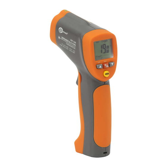
Opis funkcjonalny Opis przyrządu ① czujnik podczerwieni ② wiązka wskaźnika lasera ③ wyświetlacz LCD ④ przycisk W DÓŁ ⑤ przycisk W GÓRĘ ⑥ przycisk trybu ⑦ przycisk lasera/podświetlenia ⑧ dźwignia uruchamiania pomiarów ⑨ uchwyt ⑩ pokrywa baterii... -
Page 9: Wyświetlacz
Wyświetlacz ① zatrzy- manie wyświe- tlanych nych ② wskazania pomiarowe E symbol i wartość emi- ③ syjno- ści °C/°F symbol ④ automatyczne uzyskiwanie emisyjności ⑤ symbole włączenia blokady i lasera ⑥ symbol wartości wysokiej i niskiej ⑦ wartości temperatury dla MAX, MIN, DIF, AVG HAL, LAL i TK ⑧... -
Page 10: Przyciski
Przyciski MODE ① przycisk W GÓRĘ (dla EMS, HAL, LAL) ② cyklicznie działający przycisk TRYB (MODE) ③ przycisk W DÓŁ (dla EMS, HAL, LAL) ④ przycisk włączający lub wyłączający laser/podświetlenie... -
Page 11: Przycisk Tryb
Przycisk TRYB Miernik temperatury pracujący w podczerwieni mierzy temperaturę maksymalną (MAX), minimalną (MIN), różnicową (DIF) oraz średnią (AVG). Za każdym razem, kiedy do- konywany jest odczyt dane mogą zostać zapisane w pamięci, a na- stępnie przywołane poprzez przycisk TRYB (MODE) dopóki nie zostanie dokonany kolejny pomiar. -
Page 12: Odległość I Rozmiar Plamki
Odległość i rozmiar plamki Wraz ze wzrostem odległości (D) od obiektu, wzrasta również rozmiar plamki (S) dla obszaru mierzonego przez urządzenie. Zależność pomiędzy odległością a rozmiarem plamki dla każdego urządzenia została przedstawiona poniżej. Ognisko dla każdego urządzenia wynosi 914mm (36”). Rozmiary plamki wskazują... -
Page 13: Opis Działania
WŁĄCZENIA I WYŁĄCZENIA BLOKADY (LOCK ON/OFF) w po- łożeniu prawym. Jeśli spust pomiarowy zostaje pociągnięty, kiedy urządzenie jest zablokowane, wówczas laser oraz podświetlenie zostaną włączone, jeśli zostały one aktywowane. Kiedy urządzenie jest zablokowane, wówczas podświetlenie i laser pozostaną włą- czone do momentu, gdy zostaną one wyłączone poprzez użycie przycisku LASER/PODŚWIETLENIE znajdującego się... - Page 14 Odczekać aż taśma osiągnie tę samą temperaturę jak materiał pod nią. Zmierzyć temperaturę taśmy lub pomalowanej powierzchni. Miernik DIT-130 umożliwia kompensację błędu spowodowa- nego innym współczynnikiem emisyjności niż 0.95. W tym celu należy wprowadzić poprawną wartość emisyjności dla danej...
-
Page 15: Wykonywanie Pomiarów
Wartości emisyjności: Emisyjność Emisyjność Substancja Substancja termiczna termiczna Asfalt 0,90 do 0,98 Tkanina 0,98 (czarna) Skóra ludzka beton 0,94 0,98 Skóra Cement 0,96 0,75 do 0,80 Węgiel drzewny Piasek 0,90 0,96 (pył) Ziemia 0,92 do 0,96 Lakier 0,80 do 0,95 Woda 0,92 do 0,96 Lakier... -
Page 16: Automatyczne Uzyskiwanie Emisyjności
zasilanie miernika zostanie automatycznie wyłączone po około siedmiu sekundach od zwolnienia dźwigni (chyba, że urządze- nie jest zablokowane w pozycji pracy ciągłej (LOCK on). Automatyczne uzyskiwanie emisyj- ności W trybie emisyjności (EMS) należy trzymać spust pomiarowy wciśnięty i jednocześnie nacisnąć przycisk Laser/Podświetlenie dwukrotnie: raz krótko i raz długo, do momentu, kiedy symbol “EMS”... -
Page 17: Uwagi Dotyczące Pomiarów
otoczenia. Zazwyczaj temperatura wynosząca 100ºC jest odpowiednia dla uzyskania wartości emisyjności o większej dokładności. Uwagi dotyczące pomiarów Trzymając miernik za jego uchwyt należy skierować czujnik podczerwieni w kierunku przedmiotu, którego temperatura ma zo- stać zmierzona. Miernik automatycznie kompensuje odchylenia temperatury od temperatury otoczenia. Należy pamiętać, że dosto- sowanie do temperatury otoczenia zająć... -
Page 18: Przywoływanie Danych
Przywoływanie danych Celem przywołania zapisanych uprzednio danych po wyłącze- niu urządzenia, należy nacisnąć przycisk TRYB dopóki symbol LOG nie pojawi się w dolnym lewym rogu wyświetlacza. Numer komórki pamięci zostanie wyświetlony poniżej symbolu LOG, zaś zapisana temperatura dla tej lokacji zostanie przedstawiona na wyświetlaczu. Celem przejścia do innej komórki pamięci należy nacisnąć... -
Page 19: Konserwacja I Czyszczenie
Konserwacja i czyszczenie naprawy i czynności serwisowe nie objęte niniejszą instrukcją winny być wykonywane wyłącznie przez wykwalifikowany per- sonel, od czasu do czasu należy wyczyścić obudowę urządzenia su- chą tkaniną. Do czyszczenia urządzenia nie wolno stosować rozpuszczalników ani materiałów ściernych, ... -
Page 20: Załączniki
Zużyty sprzęt elektroniczny należy przekazać do punktu zbiórki zgodnie z Ustawą o zużytym sprzęcie elektrycznym i elektronicz- nym. Przed przekazaniem sprzętu do punktu zbiórki nie należy sa- modzielnie demontować żadnych części z tego sprzętu. Należy przestrzegać lokalnych przepisów dotyczących wyrzu- cania opakowań, zużytych baterii i akumulatorów. - Page 21 Pozostałe dane techniczne a) czas reakcji……………………………...……… poniżej 1 sekundy b) wrażliwość widmowa……….…………………..………….8~14μm c) emisyjność………………..….regulowana cyfrowo of 0,10 do 1,0 d) wskazania przekroczenia zakresu………………wyświetlacz bę- dzie wskazywał symbole “-0L”,”0L” e) biegunowość………………… automatyczna, znak minus (-) dla biegunowości ujemnej półprzewodnikowa dioda laserowa……………………..moc wyj- ściowa <1mW, długość...
-
Page 22: Wyposażenie Standardowe
Prowadzącym serwis gwarancyjny i pogwarancyjny jest: SONEL S.A. ul. Wokulskiego 11 58-100 Świdnica tel. (74) 858 38 00 (Biuro Obsługi Klienta) e-mail: bok@sonel.pl internet: www.sonel.pl Uwaga: Do prowadzenia napraw serwisowych upoważniony jest je- dynie SONEL S.A. Wyprodukowano w Chinach na zlecenie SONEL S.A. - Page 23 12.4 Usługi laboratoryjne Laboratorium Badawczo-Wzorcujące firmy SONEL S.A. oferuje usługi wzorcowania przyrządów związanych z pomiarami wielkości elektrycznych i nieelektrycznych. Wzorcowane są następujące typy przyrządów: mierniki do pomiarów wielkości elektrycznych oraz parametrów sieci energetycznych: miernik napięcia, mierniki prądu (w tym również...
- Page 24 Certyfikat Kalibracji jest dokumentem wystawianym przez pro- ducenta dla nowego fabrycznie przyrządu, kolejna kontrola me- trologiczna realizowana jest przez Laboratorium Badawczo- Wzorcujące firmy Sonel S.A., a wystawiony dokument nosi na- zwę - Świadectwo Wzorcowania. Uwaga: W przypadku przyrządów wykorzystywanych do badań związa- nych z ochroną...
-
Page 25: User Manual
USER MANUAL NON-CONTACT INFRARED THERMOMETER DIT-130 Version 1.5.1 12.02.2018... - Page 26 Main features of the DIT-130 device are the following: Precise non-contact temperature measurement. Type K temperature Measurement. Modern housing design. Built-in laser pointer. Automatic Data Hold. Automatic Power Off. °C/°F switch. Emissivity Digitally adjustable from 0,10 to 1,00.
- Page 27 TABLE OF CONTENTS 1 Safety ..............29 2 Functional description ........30 2.1 Devices description ..........30 Indicator .............. 31 2.3 Buttons ..............32 2.4 MODE Button Function .......... 33 3 Distance & Spot Size ......... 34 4 Switching F, Lock ON/OFF and Set Alarm 34 5 How it Works ............
- Page 28 Thank you for purchase of the IR Thermometer. This is capable of non-contact (infrared) temperature measurements at the touch of a button. The built-in laser pointer increases target accuracy while the backlight LCD and handy push-buttons combine for convenient, ergonomic operation. The Non-contact Infrared Thermometers can be used to meas- ure the temperature of objects’...
-
Page 29: Safety
Safety In order to guarantee proper operation and correctness of the obtained results it is necessary to observe the following recom- mendations: Use extreme caution when the laser beam is turned on. Do not let the beam enter your eye, another person’s eye or the eye of an animal. -
Page 30: Functional Description
Functional description Devices description ① IR sensor ② Laser pointer beam ③ LCD Display ④ DOWN BUTTON ⑤ UP BUTTON ⑥ MODE BUTTON ⑦ laser/backlight button ⑧ Measurement Trigger ⑨ Handle Grip ⑩ Battery Cover... -
Page 31: Indicator
Indicator ① Data hold ② Measuring indication ③ Emissivity symbol and value °C/°F symbol ④ ⑤ Auto obtain Emissivity lock and laser” on” symbols ⑥ ⑦ High alarm and low alarm symbol ⑧ Temperature values for the MAX, MIN, DIF, AVG HAL, LAL. And TK ⑨... -
Page 32: Buttons
Buttons MODE ① Up button (for EMS,HAL,LAL) ② MODE button (for cycling through the mode loop) ③ Down button (for EMS,HAL,LAL) ④ Laser/Backlight on/off button... -
Page 33: Mode Button Function
MODE Button Function infrared thermometer measures Maximum (MAX), Mini- mum (MIN), Differential (DIF), and Average (AVG) Temp. Each time you take a reading. This data is stored and can be recalled with the MODE button until a new measure- ment is taken. When the trigger is pulled again, the unit will begin measuring in the last mode selected. -
Page 34: Distance & Spot Size
Distance & Spot Size As the distance (D) from the object increases, the spot size (S) of the area measured by the unit becomes larger. The relationship between distance and spot size for each unit is listed below. The focal point for each unit is 914mm (36”). The spot sizes indicate 90% encircled energy. -
Page 35: How It Works
To lock the unit on for continuous measurement, slide the mid- dle switch LOCK ON/OFF right. If the trigger is pulled while the unit is locked on, the laser and backlight will be turned on if they have been activated. When the unit is locked on, the backlight and laser will remain on unless it is turned off using the Laser/Backlight but- ton on the keypad. - Page 36 Distance & Spot Size As the distance (D) from the object increases, the spot size (S) of the area measured by the unit becomes larger. See: Fig: 1. Locating a hot Spot To find a hot spot aim the thermometer outside the area of interest, then scan across with an up and down motion until you locate hot spot.
- Page 37 Emissivity Emissivity is a term used to describe the energy-emitting char- acteristics of materials. Most (90% of typical applications) organic materials and painted or oxidized surfaces have an emissivity of 0,95 (pre-set in the unit). Inaccurate readings will result from measuring shiny or polished metal surfaces.
-
Page 38: Measurement Operation
Measurement operation Hold the meter by its Handle Grip and point it toward the sur- face to be measured. Pull and hold the Trigger to turn the meter on and begin test- ing. The display will light if the battery is good. Replace the battery if the display does not light. -
Page 39: Measurement Considerations
The temperature of the target should be higher than the envi- ronment temperature. Normally, 100°C is suitable for obtaining a higher accuracy emissivity. After obtaining the emissivity, if the difference between IR value (in the middle of LCD) and TK value (at the lower side of LCD) is too big, the obtained emissivity will be incorrect. -
Page 40: Recalling Data
Recalling Data To recall stored data after the unit shuts off, press the MODE button until LOG appears in the lower left corner. A LOG location number will be shown below LOG, and the stored temperature for that location will be display. To move to another LOG location, press the UP and DOWN keys. -
Page 41: Cleaning And Maintenance
Attention: When making measurements with a battery's mnemonic on, one must take into account additional indefinite measure- ment uncertainty or unstable working of the meter. ② Open battery cover, then take out the battery from instrument and replace with a new 9-Volt battery and place the battery cover back. -
Page 42: Attachments
12 Attachments 12.1 Technical data The „m.v.” means the measured value of standard. Type K temperature range Temperature Resolution Basic accuracy range ±(1,5% m.v. + 3℃) -50,0…999,9℃ 0,1℃ ±(1,5% m.v. + 5℉) -58,0…999,9℉ 0,1℉ 1000…1370℃ ±(1,5% m.v. + 2℃) 1℃... -
Page 43: Standard Equipment
When accuracy is critical, make sure the target is at least twice as large as the spot size. 12.2 Standard equipment The standard set provided by the manufacturer includes the fol- lowing components: The DIT-130 meter, 9V battery, Operating manual, Carrying case, ... -
Page 44: Manufacturer
SONEL S.A. ul. Wokulskiego 11 58-100 Świdnica Tel: +48 74 858 38 60 Fax: +48 74 858 38 09 E-mail: export@sonel.pl Web page: www.sonel.pl Note: Service repairs must be realized solely by the manufacturer. Made in China for SONEL S.A. -
Page 45: Manual De Uso
MANUAL DE USO PIRÓMETRO TERMÓMETRO SIN CONTACTO QUE TRABAJA EN INFRARROJO DIT-130 Versión 1.5.1 12.02.2018... - Page 46 Las características más importantes del dispositivo DIT-130: medición de temperatura precisa sin contacto, medición de temperatura con sonda tipo K, estructura de carcasa moderna, puntero láser incorporado, función automática Data Hold (retención de datos de medición visualizados), ...
- Page 47 ÍNDICE 1 Seguridad ............50 2 Descripción funcional ........51 2.1 Descripción del dispositivo ........51 2.2 Pantalla ..............52 2.3 Botones ..............53 2.4 Botón MODO ............54 3 Distancia y tamaño del punto ......55 F, activación del 4 Cambio de unidades bloqueo de medición y los ajustes de alarma 55 5 Descripción de funcionamiento .......
- Page 49 Gracias por comprar el pirómetro DIT-130. Este dispositivo permite medir la temperatura sin contacto en infrarrojo. El puntero láser incorporado aumenta la precisión del objetivo, mientras que la pantalla LCD con iluminación de fondo y los botones prácticos proporcionan un manejo del dispositivo cómodo y ergonómico.
-
Page 50: Seguridad
Seguridad Para garantizar el servicio adecuado y la exactitud de los resultados obtenidos hay que seguir las siguientes precauciones: ser extremadamente cuidadoso cuando el haz de láser está encendido, no dirigir el haz de láser a los ojos de personas o animales, ... -
Page 51: Descripción Funcional
Descripción funcional Descripción del dispositivo ① sensor de infrarrojos ② haz del puntero láser ③ pantalla LCD ④ botón ABAJO ⑤ botón ARRIBA ⑥ botón de modo ⑦ botón de láser/iluminación de fondo ⑧ palanca de inicio de mediciones ⑨ mango ⑩... -
Page 52: Pantalla
Pantalla retención ⑫ de los datos visua- liza- ⑬ indicadores de medición E símbolo y valor de emisividad ⑭ °C/°F símbolo ⑮ recibimiento automático de emisividad ⑯ símbolos de activación del bloqueo y láser ⑰ símbolo del valor alto y bajo ⑱... -
Page 53: Botones
Botones MODE ① botón ARRIBA (para EMS, HAL, LAL) ② botón MODO (MODE) que funciona cíclicamente ③ botón ABAJO (para EMS, HAL, LAL) ④ botón para encender o apagar láser/iluminación de fondo... -
Page 54: Botón Modo
Botón MODO El medidor de temperatura que trabaja infrarrojo mide temperatura máxima (MAX), mínima (MIN), diferencial (DIF) y media (AVG). Durante cada lectura es posible almacenar los datos en la memoria que luego pueden ser mostrados con el botón MODO (MODE) hasta hacer la siguiente medición. -
Page 55: Distancia Y Tamaño Del Punto
Distancia y tamaño del punto Con el aumento de la distancia (D) desde el objeto también aumenta el tamaño del punto (S) para el área medida por el dispositivo. La relación entre la distancia y el tamaño del punto para cada dispositivo se muestra a continuación. -
Page 56: Descripción De Funcionamiento
ACTIVACIÓN Y DESACTIVACIÓN DE BLOQUEO (LOCK ON/OFF) a la derecha. Si se aprieta el gatillo de medición cuando el dispositivo está bloqueado, se encenderá el láser y la retroiluminación, si han sido activados. Cuando el dispositivo está bloqueado, entonces la retroiluminación y el láser permanecerán encendidos hasta sean... - Page 57 Distancia y tamaño del punto Con el aumento de la distancia (D) desde el objeto también aumenta el tamaño del punto (S) para el área medida por el dispositivo. Consultar la fig. 1. Determinación de la ubicación del lugar caliente Para encontrar el lugar caliente debe dirigir el medidor de temperatura fuera del área de interés, y luego buscar el área moviendo hacia arriba y abajo hasta encontrar el punto...
- Page 58 Medir la temperatura de la cinta o superficie pintada. El medidor DIT-130 permite compensar el error causado por otro factor de emisividad que 0,95. Para ello, se debe introducir el valor correcto de emisividad para la sustancia determinada.
-
Page 59: Realización De Mediciones
Realización de mediciones sujetar el medidor por el mango y dirigirlo hacia la superficie que debe ser medida, tirar y mantener presionado el gatillo de medición para encender el medidor y empezar a medir. La pantalla se iluminará si la batería está cargada adecuadamente. Se debe reemplazar la batería si la pantalla no se ilumina, ... -
Page 60: Notas Sobre Las Mediciones
Nota: Cuando el valor para el infrarrojo no corresponde al valor TK, o el valor del infrarrojo y TK se pusieron a prueba en diferentes puntos, entonces no se obtiene ningún valor de emisividad o se obtiene un valor de emisividad erróneo. Si la diferencia entre el valor para el infrarrojo (en el centro de la pantalla) y el valor TK (en la parte inferior de la pantalla) es demasiado grande, esto significa que el valor de emisividad es... -
Page 61: Memoria
Memoria Guardar los datos Este medidor de temperatura puede guardar datos para 20 mediciones. Se guarda la temperatura para infrarrojos y la escala de temperatura ( Para guardar los datos de lectura de la medición en infrarrojo se debe tirar de la palanca. Sujetando la palanca debe presionar el botón MODO (MODE) hasta que aparezca el símbolo LOG en la esquina inferior izquierda de la pantalla;... -
Page 62: Reemplazo De Batería
1. Cuando el dispositivo está en modo LOG debe presionar palanca y luego pulsar el botón de la flecha que apunta hacia abajo hasta llegar a la celda de memoria: "0". Nota: Esto se puede hacer sólo cuando la palanca está presionada. -
Page 63: Mantenimiento Y Limpieza
Mantenimiento y limpieza cualquier servicio o reparación no explicados en este manual sólo deben ser realizados por personal cualificado, limpiar la carcasa del dispositivo de vez en cuando con un paño seco. Para la limpieza no se deben utilizar disolventes ni productos abrasivos, ... -
Page 64: Archivos Adjuntos
12 Archivos adjuntos 12.1 Datos técnicos "v.m" significa el valor de medición patrón. Rango de temperatura para la sonda K Resolución Rango Incertidumbre básica de temperatura ±(1,5% v.m. + 3℃) -50,0…999,9℃ 0,1℃ ±(1,5% v.m. + 5℉) -58,0…999,9℉ 0,1℉ 1000…1370℃ ±(1,5% v.m + 2℃) 1℃... - Page 65 Otros datos técnicos a) tiempo de respuesta……………………..…inferior a 1 segundo b) sensibilidad espectral……….…………………..………….8~14μm c) emisividad………………..….ajustada digitalmente de 0,10 a 1,0 d) indicación de superación del rango………………en la pantalla aparecerán los símbolos “-0L”,”0L” e) polaridad………………… automática, el signo menos (-) para la polaridad negativa diodo láser semiconductor……………………..potencia de salida <1mW, longitud de onda 630~670nm, láser clase 2(II)
-
Page 66: Equipamiento Estándar
+48 74 858 38 60 fax +48 74 858 38 09 E-mail: export@sonel.pl Web page: www.sonel.pl Nota: Para el servicio de reparaciones sólo está autorizado SONEL S.A. El producto ha sido fabricado por encargo de Sonel S.A. en China.
Need help?
Do you have a question about the DIT-130 and is the answer not in the manual?
Questions and answers