Table of Contents
Advertisement
Advertisement
Table of Contents

Related Manuals for Sonel MIC-5010


Summary of Contents for Sonel MIC-5010
- Page 5 USER MANUAL INSULATION RESISTANCE METERS MIC-5010 and MIC-5005 SONEL S.A. Wokulskiego 11 58-100 Świdnica Version 1.11 27.07.2018...
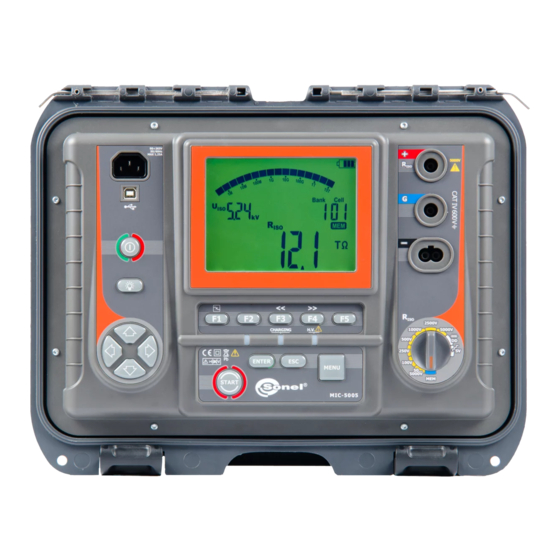
- Page 6 MIC-5010 and MIC-5005 meters are modern, high-quality, easy and safe in operation. Please acquaint yourself with the present manual in order to avoid measuring errors and prevent possible problems related to operation of the meter. MIC-5010, MIC-5005 – USER MANUAL...
-
Page 7: Table Of Contents
Measurements with increasing voltage - SV ..............16 3.1.4 Dielectric Discharge Indicator - DD .................. 19 3.2 Low-voltage measurement of resistance (MIC-5010 only) ........20 Measurement of resistance of protective conductors and equipotential bonding with ±200 3.2.1 mA current ........................20 3.2.2... -
Page 8: Safety
Safety The MIC-5010 and MIC-5005 meters are designed for performing check tests of protection against electric shock in mains systems. The meters are used for making measurements and providing results to determine safety of electrical installations. Therefore, in order to provide conditions for correct oper- ation and accuracy of obtained results, the following recommendations must be observed: ... -
Page 9: Meter Configuration
The setting sequence is as follows: Rated grid frequency (50 Hz and 60 Hz). Auto-off time (300 s, 600 s, 900 s) or none (---). MIC-5010, MIC-5005 – USER MANUAL... - Page 10 Each change sets the t1, t2 and t3 to their default values: for Ab1/Ab2 t1=15s, t2=60, t3=0, and for PI/DAR t1=30, t2=60, t3=0). Enabling ( ) and disabling ( ) the limit settings (only MIC- 5010). MIC-5010, MIC-5005 – USER MANUAL...
- Page 11 Software updates. This topic is discussed in paragraph 6. Enabling ( ) and disabling ( ) the buzzer. Test voltage accuracy: Hi – 0…5%, Lo – 0…10% MIC-5010, MIC-5005 – USER MANUAL...
-
Page 12: Measurements
The measurement result is then correct, but the test voltage on the terminals is lower than the voltage selected before the test. Current limitation can happen in the first stage of a measurement due to the object’s capacitance becoming charged. MIC-5010, MIC-5005 – USER MANUAL... -
Page 13: Double-Lead Measurement
For the position of the selector between 50...5000 V, an additional option is available to select the test voltage U The buttons are used to set the parameter value, while the but- tons move to the next parameter. MIC-5010, MIC-5005 – USER MANUAL... - Page 14 (1...600 s, but >t2) and t (independent of t1, t2 and t3: 1 s...99 min 59 s), Setting of the times t1...t3. Setting of the time t. current I : 1,2 mA or 3 mA, MIC-5010, MIC-5005 – USER MANUAL...
- Page 15 1 kΩ position or the button while in the 15 TΩ position. Press ENTER to confirm settings (confirmed by beep) or press ESC to exit without saving the changes. Connect test leads according to the drawing. MIC-5010, MIC-5005 – USER MANUAL...
- Page 16 The ability to set the filter depends on the set t measurement time, for example when t=20 s it is only possible to set the filter for 10 s. MIC-5010, MIC-5005 – USER MANUAL...
- Page 17 - A short tone informs of passing 5 s periods of time. When the timer reaches characteristic points (tx times), then for 1 s a symbol (mnemonic) of this point is displayed which is accompanied by a long beep. MIC-5010, MIC-5005 – USER MANUAL...
- Page 18 During the measurement, AC voltage appeared or the object +two-tone, continu- cannot be discharged for 30 seconds. After 5 seconds the ous beep + and LED meter returns to its default mode - voltmeter. lit in red MIC-5010, MIC-5005 – USER MANUAL...
-
Page 19: Three-Lead Measurement
G socket of the meter should be connected to the transformer tank; when measuring the insulation resistance between one of the windings and the transformer’s tank, connect G socket of the meter to the second winding: MIC-5010, MIC-5005 – USER MANUAL... -
Page 20: Measurements With Increasing Voltage - Sv
- 1 kV: 200 V, 400 V, 600 V, 800 V and 1000 V, - 2.5 kV: 500 V, 1 kV, 1.5 kV, 2 kV and 2.5 kV, MIC-5010, MIC-5005 – USER MANUAL... - Page 21 The setting sequence is as follows: maximum (final) measurement voltage: 1 kV, 2.5 kV and 5 kV, duration of individual measurements in the range between 30 s...5 min, MIC-5010, MIC-5005 – USER MANUAL...
- Page 22 2 → ..., where C - the ca- tively with R 2 and I pacity of the tested object. Note: - Further information, starting the measurement, displayed symbols, result readout and component view operate identically as the R measurement. MIC-5010, MIC-5005 – USER MANUAL...
-
Page 23: Dielectric Discharge Indicator - Dd
The measurement result testifies to the insulation condition, you may compare it with the table below: DD value Insulation condition >7 Poor Not too good <2 Set the rotary switch of function se- lection at DD. The meter is in the voltage measurement mode. MIC-5010, MIC-5005 – USER MANUAL... -
Page 24: Low-Voltage Measurement Of Resistance (Mic-5010 Only)
Note: - In an environment with strong interferences the measurement may be affected by additional uncer- tainty. 3.2 Low-voltage measurement of resistance (MIC-5010 only) 3.2.1 Measurement of resistance of protective conductors and equipotential bonding with ±200 mA current Set the rotary switch at the R CONT sition. - Page 25 1 kΩ position or the button while in the 999 Ω position. Connect the meter to the tested object. Trigger the measurement by pressing the START push-button. Read out the result. MIC-5010, MIC-5005 – USER MANUAL...
-
Page 26: Calibration Of Test Leads
In order to remove the calibration made (return to default calibra- tion), perform the above-mentioned activities with test leads open; the sign shall appear. MIC-5010, MIC-5005 – USER MANUAL... -
Page 27: Memory Of Measurement Results
Memory of measurement results The MIC-5010 and MIC-5005 meters are equipped with a memory capable of storing 11880 single test results (990 cells, each may contain a set of measurements of: R and R ). The whole memory CONT is divided into 10 memory banks each of them containing 99 memory cells. Thanks to dynamic memory allocation, each of the memory cells can contain different quantity of single measurement results, de- pending on the needs. - Page 28 Press ESC to return to displayed result without sav- ing. If you try to store data in an occupied memory cell, the following warn- ing message will appear: MIC-5010, MIC-5005 – USER MANUAL...
-
Page 29: Viewing Memory Data
/ memory displays alternately bank and cell numbers and the time in which the result was entered into memory. This applies to all R measurements. 4.3 Deleting memory data You can delete the entire memory or its individual banks. MIC-5010, MIC-5005 – USER MANUAL... -
Page 30: Deleting Bank Data
Set the cell ID using the buttons in front of "1"..the cell number disap- pears, and the sym- bol indicating the readi- ness to delete appears. Press ENTERpush-button. symbols appear, asking you to confirm deletion. MIC-5010, MIC-5005 – USER MANUAL... -
Page 31: Deleting The Whole Memory
Set the rotary switch of function selec- tion at MEMposition. Set the bank ID using the buttons in front of "1"..the bank ID disappears, and the symbol displayed, indicating the readiness to delete. Press ENTER push-button. MIC-5010, MIC-5005 – USER MANUAL... - Page 32 Press ENTER again. After deleting the bank, the meter beeps three times and sets the bank and cell numbers as "1." MIC-5010, MIC-5005 – USER MANUAL...
-
Page 33: Data Transmission
Bluetooth wireless module with an additional software (Sonel Reader - supplied or available for down- load from the website, Sonel PE5). If the required software has not been purchased with the meter, it may be obtained form the manufacturer or form an authorised distributor. - Page 34 Standard pin for Bluetooth is "0123". - The data transmission may be interrupted using the ESC button - the meter then enters the memory viewing mode. - With the USB cable active the wireless transmission is not possible. MIC-5010, MIC-5005 – USER MANUAL...
-
Page 35: Software Updates
Turn on the meter by pressing and holding the MENU button. Using the buttons display the follow- ing screen. flashes Connect the meter to the computer using an USB cable and press ENTER. Follow the instructions of the software. MIC-5010, MIC-5005 – USER MANUAL... -
Page 36: Power Supply Of The Meter
5 s. 7.2 Battery power The MIC-5010 meter is powered with a Li-Ion battery which may only be replaced in a repair shop. NOTE: In MIC-5010 up to SN: B20319 and MIC-5005 up to SN: B10644 gel batteries are used. -
Page 37: Mains Power
- Do not charge or use the batteries in extreme temperatures. Extreme temperatures reduce the lifetime of rechargeable batteries. Always observe the rated operating temperature. Do not dispose the battery pack into fire. MIC-5010, MIC-5005 – USER MANUAL... -
Page 38: General Principles For Using Gel (Lead) Rechargeable Batteries
- Charging may only be performed using a charger with specific parameters and under the conditions set by their manufacturers. Failure to meet these conditions can lead to leakage, overheating or even an explosion. MIC-5010, MIC-5005 – USER MANUAL... -
Page 39: Cleaning And Maintenance
Worn-out electronic equipment should be sent to a collection point in accordance with the law of waste electrical and electronic equipment. Before the equipment is sent to a collection point, do not dismantle any elements. Observe local regulations concerning disposal of packages, waste batteries and accumulators. MIC-5010, MIC-5005 – USER MANUAL... -
Page 40: Technical Specifications
2500 V 5.00 T 5000 V 15.0 T Note: For insulation resistance below R there is no accuracy specified because the meter ISOmin works with the adjustable current limit in accordance with the following formula: MIC-5010, MIC-5005 – USER MANUAL... - Page 41 EN 60529......IP40 (IP67 for closed enclosure) d) power supply of the meter..............14.8 V 5.3 Ah Li-Ion battery, (gel battery 12 V for MIC-5010 up to SN: B20319 and MIC-5005 up to SN: B10644), mains 90 V ÷ 260 V 50 Hz/60 Hz...
-
Page 42: Additional Data
............EN 61326-1:2006 and EN 61326-2-2:2006 ATTENTION! MIC-5010 and MIC-5005 meters are classified in terms of Electromagnetic Com- patibility (EMC) as instruments of Class A (for use in industrial environments - according to EN 50011). Interferences, impacting the operation of other de- vices must be taken into account when the meters are used in other environ- ments (e.g. -
Page 43: Equipment
12.1 Standard equipment The standard set of equipment supplied by the manufacturer includes: MIC-5010 meter – WMPLMIC5010 or MIC-5005 meter– WMPLMIC5005 set of test leads: 10 kV 1.8 m lead cat. IV 1000 V terminated with banana plugs, red – WAPRZ1X8REBB10K ... - Page 44 20 m red lead 10 kV, terminated with ba- nana plugs nana plugs WAPRZ010BUBB10K WAPRZ020BUBB10K 10 m blue lead 10 kV, terminated with 20 m blue lead 10 kV, terminated with ba- banana plugs nana plugs LSWPLMIC5010 LSWPLMIC5005 calibration certificate MIC-5010, MIC-5005 – USER MANUAL...
-
Page 45: Manufacturer
The manufacturer of the device and provider of guarantee and post-guarantee service: SONEL S.A. Wokulskiego 11 58-100 Świdnica Poland tel. +48 74 858 38 60 fax +48 74 858 38 09 E-mail: export@sonel.pl Web page: www.sonel.pl MIC-5010, MIC-5005 – USER MANUAL... - Page 46 14 Laboratory services SONEL Testing and Calibration Laboratory has been accredited by the Polish Center of Accredita- tion for the calibration of measuring instruments AP 173 in the following field - electrical properties in DC and LF circuits: voltage and current (DC), voltage and current (AC), resistance (DC), electrical power.
- Page 47 NOTES MIC-5010, MIC-5005 – USER MANUAL...
- Page 48 NOTES MIC-5010, MIC-5005 – USER MANUAL...
Need help?
Do you have a question about the MIC-5010 and is the answer not in the manual?
Questions and answers