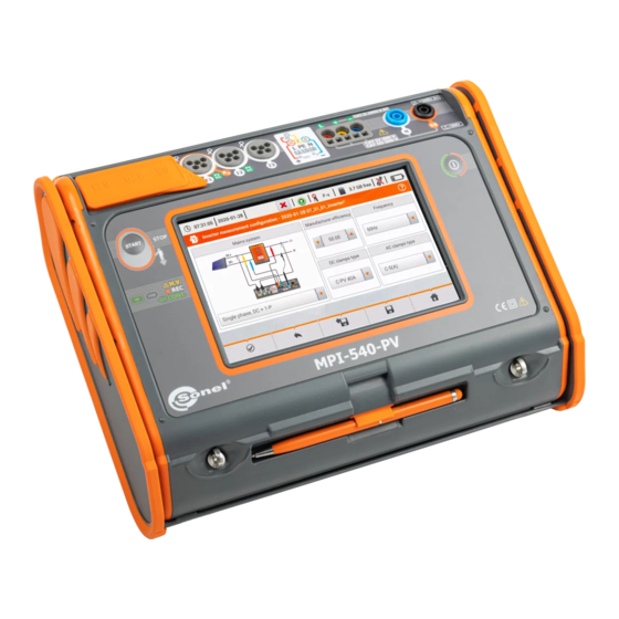
Sonel MPI-540 User Manual
Meter for electrical installation parameters
Hide thumbs
Also See for MPI-540:
- User manual (208 pages) ,
- Brief user manual (60 pages) ,
- Brief user manual (76 pages)
Table of Contents
Advertisement
Quick Links
Advertisement
Table of Contents

Related Manuals for Sonel MPI-540


Summary of Contents for Sonel MPI-540
- Page 3 USER MANUAL METER FOR ELECTRICAL INSTALLATION PARAMETERS MPI-540 ● MPI-540-PV SONEL S.A. Wokulskiego 11 58-100 Świdnica Poland Version 2.08 10.10.2022...
- Page 4 MPI-540 / 540-PV meter is a modern, easy in use and safe measuring device. Please acquaint your- self with this manual in order to avoid measuring errors and prevent possible problems in operation of the meter. MPI-540 ● MPI-540-PV – USER MANUAL...
-
Page 5: Table Of Contents
3.8 RCD parameters ....................67 3.8.1 Settings of measurements ..................... 67 3.8.2 RCD tripping current ...................... 70 3.8.3 RCD tripping time ......................73 3.8.4 Measurements in IT networks ..................76 3.9 Automatic measurements of RCD parameters ............77 MPI-540 ● MPI-540-PV – USER MANUAL... - Page 6 5.6.1 Transient waveforms of current and voltages (waveforms) ........... 137 5.6.2 Timeplot of effective values ..................139 5.6.3 "Live" mode - tabular view .................... 140 5.6.4 Vector diagram of fundamental components (phasor) ..........142 MPI-540 ● MPI-540-PV – USER MANUAL...
- Page 7 Memory Card ....................176 6.2.2 USB external memory (flash drive)................176 6.2.3 Compatibility with Sonel Analysis software ..............176 6.2.4 PC connection and data transmission ................176 7 Power supply ....................178 7.1 Monitoring of the battery charge status ..............178 7.2 Replacing rechargeable batteries .................
- Page 8 12 Accessories ....................199 12.1 Standard accessories ................... 199 12.2 Optional accessories .................... 200 12.2.1 C-PV clamp ....................206 13 Positions of the meter’s cover ..............207 14 Manufacturer ....................207 15 Laboratory services ..................208 MPI-540 ● MPI-540-PV – USER MANUAL...
-
Page 9: Safety
All other parts of the text relate to all types of the instrument. Safety MPI-540 meter is designed for performing check tests of protection against electric shock in AC mains systems and recording the parameters of electric mains. The meter is used for making meas- urements and providing results to determine safety of electrical installations. -
Page 10: Main Menu
Touching a selected main menu item redirects to the sub-menu. Available options: Recorder – measurement of electrical parameters of the tested network. The description of the recording mode is provided in section 5 , MPI-540 ● MPI-540-PV – USER MANUAL... -
Page 11: Meter Settings
The date , time and display brightness can be set from the Meter settings screen level. main menu select Settings. Select Meter settings Parameters to change Date time (section 2.1.1) Auto off (section 2.1.2) Display (section 2.1.3) MPI-540 ● MPI-540-PV – USER MANUAL... -
Page 12: Setting Date And Time
(step Delete the existing entry and enter the required value manually. Functions of icons reject the changes and return to step accept changes and go to step MPI-540 ● MPI-540-PV – USER MANUAL... -
Page 13: Automatic Shutdown
After touching the icon you may be prompted to save or re- ject changes (figure): Yes – accept selection, No – reject changes, Cancel – cancel the action saving changes return to the main menu MPI-540 ● MPI-540-PV – USER MANUAL... -
Page 14: Display Parameters
After touching the icon you may be prompted to save or reject changes: Yes – accept selection, No – reject changes, Cancel – cancel the action saving changes return to the main menu MPI-540 ● MPI-540-PV – USER MANUAL... -
Page 15: Settings Of Measurements
6.1.3) to be placed in an automatically created new measurement point (section b step Auto measurements timer determines the time interval of starting subsequent steps of the measurement procedure. Expand the selection list using the icon. Select the required parameter value. MPI-540 ● MPI-540-PV – USER MANUAL... -
Page 16: Sub-Menu Edit Fuses
On the Fuse base screen the following parameters of circuit breakers can be defined and edited: manufacturer, model (type) of fuse, characteristic of fuse. a. Adding fuse characteristics Select the icon. A menu will appear for adding time-current characteristics of fuses. MPI-540 ● MPI-540-PV – USER MANUAL... - Page 17 Enter the name from the touch keypad (holding certain buttons for a longer time triggers Polish characters). Functions of icons rejecting changes and return- ing to step accepting changes and going to step MPI-540 ● MPI-540-PV – USER MANUAL...
- Page 18 Activate the created characteris- Add rated fuse current using icon Editing fuse data proceed as in steps To activate a row of data, select any item in the row. Icons will be activat- MPI-540 ● MPI-540-PV – USER MANUAL...
- Page 19 Cancel – cancel changes You will be prompted to conform the selection. Description of function icons Yes – accept selection No – reject changes To change the contents of a se- lected cell, touch it twice. MPI-540 ● MPI-540-PV – USER MANUAL...
- Page 20 Functions of icons reject changes and return to the menu for adding charac- teristics accept changes and return to the menu for adding charac- teristics Select the icon and return to the fuse base menu. MPI-540 ● MPI-540-PV – USER MANUAL...
-
Page 21: Adding Fuses
Touch the name input field. Enter the name from the touch keypad (holding certain buttons for a longer time triggers addi- tional characters). Functions of icons reject the changes accept changes and go to step ▼ ▼ MPI-540 ● MPI-540-PV – USER MANUAL... - Page 22 Enter the fuse characteristic from list. Description of function icons record inactive record active add new record edit active record name remove active record return to the previous screen return to the main menu MPI-540 ● MPI-540-PV – USER MANUAL...
-
Page 23: Sub-Menu Pv Modules
NOCT – nominal operation cells temperature alpha – temperature current coefficient - Isc beta – temperature voltage coefficient - Uoc gamma – temperature power coefficient - Pmax - serial resistance of PV module * MPP – maximum power point MPI-540 ● MPI-540-PV – USER MANUAL... -
Page 24: Communication
It enables data reading from the recorder and data analysis. Sonel Reader – the software is used to retrieve the data saved from the meter memory. In addition, it enables data transfer to the PC, data saving in popular formats and printing. -
Page 25: E-Mail Settings
2.4.1 Update via USB The update file can be downloaded from the manufacturer's website (www.sonel.com). Save the file to a USB drive. The memory must have the FAT32 file system. Select Settings ► Software update to open the update menu. -
Page 26: Update Via Wi-Fi
If the changes have not been saved or the icon was select- ed, a prompt will appear to confirm the selection. Description of function icons Yes – accept selection No – reject selection Cancel – cancel the action MPI-540 ● MPI-540-PV – USER MANUAL... -
Page 27: Meter Information
Description of function icons return to the previous screen (you may be prompted to save or reject changes) display detailed information return to the main menu The screen after selecting icon MPI-540 ● MPI-540-PV – USER MANUAL... -
Page 28: Measurements
The result of the last measurement is displayed until: next measurement starts, measurement parameters are changed, measurement function is changed, the meter is switched off. The last measurement can be recalled using the icon. MPI-540 ● MPI-540-PV – USER MANUAL... -
Page 29: Diagnostics Performed By The Meter - Limits
L-PE L-PE[RCD] RCD I RCD t CONT Phase sequence Motor rotation Resistance-to-earth R Soil resistivity Illuminance Recorder MPI-540 ● MPI-540-PV – USER MANUAL... -
Page 30: Checking The Correctness Of Pe (Protective Earth) Connections
If the voltage on the PE conductor exceeds the acceptable limit value (approx 50 V), the meter will signal the fact. If the IT network has been selected in section 2.2.1 step , the contact electrode is inactive. MPI-540 ● MPI-540-PV – USER MANUAL... -
Page 31: Fault Loop Parameters
rated network voltage U voltage measured by the me- ter U The physical meaning of the pa- rameter is presented in section 3.4.5. Touch the drop-down list field. Select the required value. MPI-540 ● MPI-540-PV – USER MANUAL... - Page 32 The current is calculated after set- ting parameters in steps – current ensuring automatic triggering of a protective device within a required time. Description of function icons Ok – accept fuse settings Cancel – cancel the action MPI-540 ● MPI-540-PV – USER MANUAL...
-
Page 33: Fault Loop Parameters In The L-N And L-L Circuits
The measurement screen will ap- pear. Live mode – current voltage between phase and neutral conductors f – current frequency on the test- ed object Enter the measurement settings in accordance with section 3.4.1. MPI-540 ● MPI-540-PV – USER MANUAL... - Page 34 Minimum interval between successive measurements is 5 seconds. The displayed message indicates that it is possible to perform another measurement. Un- til the message is displayed, the meter prevents any measurements. MPI-540 ● MPI-540-PV – USER MANUAL...
- Page 35 The voltage on the tested object is not within the limits specified for the set rated voltage of the network U (sec- tion 2.2.1 step Too low value of the prospective short circuit current I the pre-set fuse and time of its triggering. MPI-540 ● MPI-540-PV – USER MANUAL...
-
Page 36: Fault Loop Parameters In The L-Pe Circuit
Connect test leads according to Fig. 3.1 or Fig. 3.2. Fig. 3.1 Measurement in L-PE circuit Fig. 3.2 Checking effectiveness of protection against electric shock of the meter housing in case of: TN network or TT network MPI-540 ● MPI-540-PV – USER MANUAL... - Page 37 – current ensuring automatic triggering of a selected protective device within a required time After selecting the bar on the right side, a menu will slide out with additional measurement re- sults. MPI-540 ● MPI-540-PV – USER MANUAL...
- Page 38 Minimum interval between successive measurements is 5 seconds. The displayed message indicates that it is possible to perform another measurement. Un- til the message is displayed, the meter prevents any measurements. MPI-540 ● MPI-540-PV – USER MANUAL...
-
Page 39: Fault Loop Impedance In L-Pe Circuit Protected With A Residual Current Device (Rcd)
Fault loop impedance in L-PE circuit protected with a residual cur- rent device (RCD) Connect test leads according to Fig. 3.3 , Fig. 3.4 or Fig. 3.5. Fig. 3.3 Measurement in the TN-S system Fig. 3.4 Measurement in the TT system MPI-540 ● MPI-540-PV – USER MANUAL... - Page 40 – current voltage between L-PE phase and protective conductors f – current frequency on the test- ed object Enter the measurement settings in accordance with section 3.4.1. Press the START button to per- form measurement. MPI-540 ● MPI-540-PV – USER MANUAL...
- Page 41 After approx. 15 consecutive measurements of the fault loop wait until the instru- ment cools down. This limitation is due to the high current measurement and multi- functionality of the meter. Minimum interval between successive measurements is 5 seconds. The displayed MPI-540 ● MPI-540-PV – USER MANUAL...
-
Page 42: Prospective Short-Circuit Current
L-L' Zakresy napięć U , dla których Zakresy napięć U , dla których short-circuit current is calculated short-circuit current is calculated liczony jest prąd zwarciowy liczony jest prąd zwarciowy Fig. 3.6 Measuring voltage ranges MPI-540 ● MPI-540-PV – USER MANUAL... -
Page 43: Measurement Of Fault Loop Impedance In It Networks
The manner of connecting the device to the installation is shown in Fig. 3.7. The manner of performing the fault loop measurements is described in section 3.4.2. Operating voltage range: 95 V … 440 V. Fig. 3.7 Measurement in the IT system MPI-540 ● MPI-540-PV – USER MANUAL... -
Page 44: Voltage Drop
Enter the limit of voltage drop ΔU Enter the fuse type, which pro- tects the tested circuit. Connect the meter to the reference point of the tested network, as for Z measurement Press START. MPI-540 ● MPI-540-PV – USER MANUAL... - Page 45 A detailed description of memory management is contained in section 6.1.3. The last measurement can be recalled us- ing the icon. is greater than Z, then the meter indicates ΔU = 0% If Z MPI-540 ● MPI-540-PV – USER MANUAL...
-
Page 46: Resistance-To-Earth
Resistance-to-earth 3.6.1 Settings of measurements Select item R Touch the parameter drop-down menu Un (measuring voltage se- lection). Select the required measuring voltage from the list. Touch the drop-down menu of measurement method selection. MPI-540 ● MPI-540-PV – USER MANUAL... - Page 47 Select Limit to set the resistance limit. Select unit. Enter the required resistance limit value: 0.00…1990 for Ω, 0.00…2 for kΩ. Functions of icons reject changes and exit to the previous screen accept changes MPI-540 ● MPI-540-PV – USER MANUAL...
-
Page 48: Earth Resistance Measurement With 3-Pole Method (R 3P)
It is recommended that the tested earth electrode as well as H and S electrodes should be located along one line and at relevant distances, in accordance with the rules of earth measurements. MPI-540 ● MPI-540-PV – USER MANUAL... - Page 49 After selecting the bar on the right side, a menu will slide out with additional measurement re- sults. MPI-540 ● MPI-540-PV – USER MANUAL...
- Page 50 24 V. Voltage of interferences is measured up to the level of 100 V. Over 50 V it is signalled as hazardous. The meter must not be connected to voltages exceeding 100 V. MPI-540 ● MPI-540-PV – USER MANUAL...
- Page 51 Error due to the resistance of electrodes > 30 % (for calcu- lating uncertainty, measured values are taken into ac- count). Interruption in measuring circuit or resistance of test probes is higher than 60 kΩ. MPI-540 ● MPI-540-PV – USER MANUAL...
-
Page 52: Earth Resistance Measurement With 4-Wire Method (R 4P)
It is recommended that the tested earth electrode as well as H and S electrodes should be located along one line and at relevant distances, in accordance with the rules of earth measurements. MPI-540 ● MPI-540-PV – USER MANUAL... - Page 53 After selecting the bar on the right side, a menu will slide out with additional measurement re- sults. MPI-540 ● MPI-540-PV – USER MANUAL...
- Page 54 24 V. Voltage of interferences is measured up to the level of 100 V. Over 50 V it is signalled as hazardous. The meter must not be connected to voltages exceeding 100 V. MPI-540 ● MPI-540-PV – USER MANUAL...
- Page 55 Error due to the resistance of electrodes > 30 % (for calcu- lating uncertainty, measured values are taken into ac- count). Interruption in measuring circuit or resistance of test probes is higher than 60 kΩ. MPI-540 ● MPI-540-PV – USER MANUAL...
-
Page 56: Earth Resistance Measurement With 3-Pole Method With Additional Clamp
E lead. The arrow on the clamps can be directed in any direction. Select the 3P + clamps option in the measurement menu. Select other settings in accord- ance with section 3.6.1. MPI-540 ● MPI-540-PV – USER MANUAL... - Page 57 Selecting the bar hides the menu. Save the measurement to the meter memory using the icon. A detailed description of memory management is contained in section 6.1.3. The last measurement can be recalled us- MPI-540 ● MPI-540-PV – USER MANUAL...
- Page 58 Then, in accordance with the formulas from section 11.4.4, calculations can be made to estimate the influence of measurement conditions. To reduce the uncertainty of the δ, measurement, the contact of the probe with earth MPI-540 ● MPI-540-PV – USER MANUAL...
- Page 59 Interruption in measuring circuit or resistance of test probes is higher than 60 kΩ. Interruption in the test probe circuit. Interruption in the voltage probe circuit. Too small test current. No continuity in the current clamps circuit. MPI-540 ● MPI-540-PV – USER MANUAL...
- Page 60 30 cm from each other. The arrow on the clamps can be directed in any direction. Connect the transmitting clamps N-1 to H and E socket. Connect the measuring clamps C-3 to the clamp socket. MPI-540 ● MPI-540-PV – USER MANUAL...
- Page 61 Save the measurement to the meter memory using the icon. A detailed description of memory management is contained in section 6.1.3. The last measurement can be re- called using the icon. MPI-540 ● MPI-540-PV – USER MANUAL...
- Page 62 Signal / noise ratio is too low (interfering signal too large). Error due to the resistance of electrodes > 30 % (for calcu- lating uncertainty, measured values are taken into ac- count). Too small test current. No continuity in the current clamps circuit. MPI-540 ● MPI-540-PV – USER MANUAL...
-
Page 63: Soil Resistivity
L – distance between the electrodes (all distances must be equal), – measured resistance. 3.7.1 Settings of measurements Select item Ωm. Touch the parameter drop-down menu Un (measuring voltage se- lection). Select the required measuring voltage from the list. MPI-540 ● MPI-540-PV – USER MANUAL... -
Page 64: Main Elements Of The Screen
The measurement screen will appear. Live mode U – interference voltage Limits ρ – soil resistivity limit After selecting the bar on the right side, a menu will slide out with additional measurement results. MPI-540 ● MPI-540-PV – USER MANUAL... -
Page 65: Soil Resistivity Measurements (Ρ)
3.7.3 Soil resistivity measurements (ρ) Drive 4 probes into the ground in one line and at equal distances. Connect the probes to the meter according to the figure above. MPI-540 ● MPI-540-PV – USER MANUAL... - Page 66 (range 1…30 Functions of icons reject changes and exit to the previous screen accept changes The meter is ready for measure- ment. Press START to start the meas- urement. MPI-540 ● MPI-540-PV – USER MANUAL...
- Page 67 24 V. Voltage of interferences is measured up to the level of 100 V. Over 50 V it is signalled as hazardous. The meter must not be connected to voltages exceeding 100 V. MPI-540 ● MPI-540-PV – USER MANUAL...
- Page 68 Error due to the resistance of electrodes > 30 % (for calcu- lating uncertainty, measured values are taken into ac- count). Interruption in measuring circuit or resistance of test probes is higher than 60 kΩ. MPI-540 ● MPI-540-PV – USER MANUAL...
-
Page 69: Rcd Parameters
– RCD triggering time when measuring tripping current. For RCD t the following pa- rameters are available: – voltage measured on PE, – PE continuity, – RCD triggering time when given the rated differential cur- rent ratio. MPI-540 ● MPI-540-PV – USER MANUAL... - Page 70 Rated differential currents of RCDs are available in the menu. Touch the drop-down list field. Select the residual current of the test circuit breaker. MPI-540 ● MPI-540-PV – USER MANUAL...
- Page 71 RCD. Touch the drop-down list field. Select the waveform of the measuring current. Determine the type of circuit breaker. Available circuit breaker types general purpose short-time delay type selective MPI-540 ● MPI-540-PV – USER MANUAL...
-
Page 72: Rcd Tripping Current
U – voltage between phase con- ductor L and PE conductor f – network frequency in the test- ed circuit Press START to start the meas- urement. To cancel measurement, select icon on the screen. MPI-540 ● MPI-540-PV – USER MANUAL... - Page 73 = f (I Δn Therefore, when time t is s correct (not too long), it may be assumed that the time measured in function t would be also correct (it would not be longer). MPI-540 ● MPI-540-PV – USER MANUAL...
- Page 74 L and N in the mains socket). Network frequency is outside the range of 45...65 Hz. PE conductor connected incorrectly. Measurement error. Before measurement, voltage at test terminals exceeds 500 V. MPI-540 ● MPI-540-PV – USER MANUAL...
-
Page 75: Rcd Tripping Time
The meter is ready for measure- ment. Live mode U – voltage between phase con- ductor L and PE conductor f – network frequency in the test- ed circuit Press START to start the meas- urement. MPI-540 ● MPI-540-PV – USER MANUAL... - Page 76 Save the measurement to the meter memory using the icon. A detailed description of memory management is contained in section 6.1.3. The last measurement can be recalled us- ing the icon. MPI-540 ● MPI-540-PV – USER MANUAL...
- Page 77 L and N in the mains socket). Maximum temperature of the meter is exceeded. Network frequency is outside the range of 45...65 Hz. PE conductor connected incorrectly. Measurement error. Before measurement, voltage at test terminals exceeds 500 V. Voltage exceeded. MPI-540 ● MPI-540-PV – USER MANUAL...
-
Page 78: Measurements In It Networks
Fig. 3.9 RCD testing without the PE conductor The manner in which the measurements of current and the RCD triggering time has been de- scribed in section 3.8.2,3.8.3. Operating voltage range: 95 V … 270 V. MPI-540 ● MPI-540-PV – USER MANUAL... -
Page 79: Automatic Measurements Of Rcd Parameters
(sec. 2.2.1), determine the multiplication factor of the 6 mA DC dif- ferential current (EV button). The test settings vary de- pending on the selected standard. MPI-540 ● MPI-540-PV – USER MANUAL... -
Page 80: Automatic Measurement Of Rcds
Enter the measurement settings in accordance with section 3.9.1. The meter is ready for measure- ment. Live mode U – voltage between phase con- ductor L and PE conductor f – network frequency in the test- ed circuit MPI-540 ● MPI-540-PV – USER MANUAL... - Page 81 Save the measurement to the meter memory using the icon. A detailed description of memory management is contained in section 6.1.3. The last measurement can be recalled us- ing the icon. MPI-540 ● MPI-540-PV – USER MANUAL...
- Page 82 ≤ 100 ms at 33 I Δn = 200 mA acc. to IEC 62955) Δ for 6 mA RCD and RCM ≤ 40 ms at 50 I Δn = 300 mA acc. to IEC 62752) Δ MPI-540 ● MPI-540-PV – USER MANUAL...
- Page 83 L and N in the mains socket). Maximum temperature of the meter is exceeded. Network frequency is outside the range of 45...65 Hz. PE conductor connected incorrectly. Measurement error. Before measurement, voltage at test terminals exceeds 500 V. Voltage exceeded. MPI-540 ● MPI-540-PV – USER MANUAL...
-
Page 84: Insulation Resistance
(N)(PE)(L) – if the phase conductor on the right rela- tive to the socket protective pin, (L+N)(PE) – shorted L and N conductors, measurement to PE (simplified method). MPI-540 ● MPI-540-PV – USER MANUAL... - Page 85 Touch the drop down menu to set the measuring voltage Un. Select the required measuring voltage from the list. Set the measurement duration using the icon. After the selection has been made, it will display the set value. MPI-540 ● MPI-540-PV – USER MANUAL...
- Page 86 1…60 s. Functions of icons reject changes and exit to the previous screen accept changes Description of function icons Ok – accept selection Cancel – reject changes MPI-540 ● MPI-540-PV – USER MANUAL...
- Page 87 Ranges: kΩ: 0…2 000 000, MΩ: 0.0…2000.0, GΩ: 0.000…2.000. Functions of icons rejecting changes and exit to the previous screen accepting changes returning previous screen going to the main menu MPI-540 ● MPI-540-PV – USER MANUAL...
-
Page 88: Measurement Using Probes
In order to interrupt the meas- urement, press START. If continuous measurement has been selected (icon ), a prompt will appear to confirm the start of the measurement. During measurement H.V./REC/CONT. diode is lit in orange. MPI-540 ● MPI-540-PV – USER MANUAL... - Page 89 If it is displayed after the measurement, it means that the meas- urement result was obtained during operation with a cur- rent limiting device (e.g. short circuit on the test object). MPI-540 ● MPI-540-PV – USER MANUAL...
-
Page 90: Measurements Using Uni-Schuko Adapter (Ws-03 And Ws-04)
WS-04 adapter with UNI-Schuko outlet plug. The meter detects this fact auto- matically and changes the ap- pearance of the screen. Enter the measurement settings in accordance with section 3.10.1 Connect the adapter to the test socket. MPI-540 ● MPI-540-PV – USER MANUAL... - Page 91 Save the measurement to the meter memory using the icon. A detailed description of memory management is contained in section 6.1.3. The last measurement can be recalled us- ing the icon. MPI-540 ● MPI-540-PV – USER MANUAL...
- Page 92 If it is displayed after the measurement, it means that the meas- urement result was obtained during operation with a cur- rent limiting device (e.g. short circuit in the test object). MPI-540 ● MPI-540-PV – USER MANUAL...
-
Page 93: Measurements Using Autoiso-1000C
Enter the measurement settings in accordance with section 3.10.1. The meter is ready for measure- ment. Live mode U – interference voltage Description of function icons scrolling down the list of measurements scrolling up the list of meas- urements MPI-540 ● MPI-540-PV – USER MANUAL... - Page 94 The display shows the symbol of the resistance being measured and the progress bar of this measurement. The bar shows % of progress of total measurement. The measurement may be can- celled at any time using the icon. MPI-540 ● MPI-540-PV – USER MANUAL...
- Page 95 (and also when 110% of the preset value is exceeded). After completion of measurement, the capacitance of the object tested is discharged – terminals with resistance of 100 kΩ. by shorting R + and R MPI-540 ● MPI-540-PV – USER MANUAL...
- Page 96 If it is displayed after the measurement, it means that the meas- urement result was obtained during operation with a cur- rent limiting device (e.g. short circuit in the test object). MPI-540 ● MPI-540-PV – USER MANUAL...
-
Page 97: Low-Voltage Resistance Measurement
To disable compensation of the resistance of leads, repeat steps with open test leads. Then the measurement result will contain the resistance of test leads. MPI-540 ● MPI-540-PV – USER MANUAL... - Page 98 Read out the result. NOTE! Display of symbols indicates that the tested object is live. The meas- urement is blocked. The meter must be immediately disconnected from the object. MPI-540 ● MPI-540-PV – USER MANUAL...
- Page 99 Measurement in progress Incorrect voltage on object. Interference voltage occurs on the tested object. The meas- urement is possible however it will be burdened with addi- tional uncertainty that is specified in the technical data. MPI-540 ● MPI-540-PV – USER MANUAL...
-
Page 100: Measurement Of Resistance Of Protective Conductors And Equipotential Bonding With ±200 Ma Current
Description of function icons Yes – accept selection No – cancels the action After selecting Yes the meter will measure resistance of test leads 3 times. Then it will give the re- sult reduced by this resistance. MPI-540 ● MPI-540-PV – USER MANUAL... - Page 101 Using the on-screen keyboard de- lete the existing value and enter the required one. Range: 0…400 Ω Functions of icons reject changes and exit to the previous screen accept changes MPI-540 ● MPI-540-PV – USER MANUAL...
- Page 102 After selecting the bar on the right side, a menu will slide out with additional measurement re- sults. MPI-540 ● MPI-540-PV – USER MANUAL...
- Page 103 Too high voltage on the tested object. Interference voltage occurs on the tested object. The meas- urement is possible however it will be burdened with addi- tional uncertainty that is specified in the technical data. MPI-540 ● MPI-540-PV – USER MANUAL...
-
Page 104: Phase Sequence
Connect the meter to the installation according to the drawing. The meter ready for testing. L1-L2 L2-L3 L3-L1 values of phase-to-phase voltag- signalling the presence of indi- vidual phases The phase sequence is correct , i.e. the phase sequence is in clockwise direction. MPI-540 ● MPI-540-PV – USER MANUAL... -
Page 105: Motor Rotation Direction
The meter ready for testing. Connect the meter to the mo- tor according to the drawing, i.e. U terminal do input L1, V to L2, W to L3. Vigorously rotate the motor shaft to the right. MPI-540 ● MPI-540-PV – USER MANUAL... - Page 106 Do not move the test leads during the test. Moving disconnected test leads, may induce voltages that result in indicating the di- rection of rotation. MPI-540 ● MPI-540-PV – USER MANUAL...
-
Page 107: Illuminance
The meter is ready for light measurement. Live mode E [lx] – illumination expressed in lux (lm/m E [fc] – illumination expressed in lm/ft (lumen per square foot) – limit set in steps MPI-540 ● MPI-540-PV – USER MANUAL... -
Page 108: Resistance-To-Earth (Pv)
Save the measurement to the meter memory using the icon. A detailed description of memory management is contained in section 6.1.3. 3.15 Resistance-to-earth (PV) Connect the measuring system. The measurement is performed similarly as in section 3.6. MPI-540 ● MPI-540-PV – USER MANUAL... -
Page 109: Insulation Resistance (Pv)
– measurement voltage Selecting the bar hides the menu. 3.17 Continuity of connections (PV) Connect the measuring system. The measurement is performed similarly as in sec. 3.11.2. MPI-540 ● MPI-540-PV – USER MANUAL... -
Page 110: Open Circuit Dc Voltage Uoc
M – number of modules in series, assessment not possible N – number of modules connected in parallel, – temperature of the module. Selecting the bar hides the menu. MPI-540 ● MPI-540-PV – USER MANUAL... -
Page 111: Short Circuit Dc Current Isc
M – number of modules in series, assessment not possible N – number of modules connected in parallel, – temperature of the module. Selecting the bar hides the menu. MPI-540 ● MPI-540-PV – USER MANUAL... -
Page 112: Test Of The Inverter Panel Η, P, I
If necessary, reset the clamp again. Use icon ► to go to the measure- ment configuration. See sec. 3.20.1, 3.20.2. MPI-540 ● MPI-540-PV – USER MANUAL... -
Page 113: Measurement Configuration
– voltage measured on DC side – current measured on AC side – current measured on DC side Selecting the bar hides the menu. 3.20.1 Measurement configuration Fig. 3.10. Configuration screen of inverter efficiency measurement MPI-540 ● MPI-540-PV – USER MANUAL... - Page 114 AC clamps type – the user may use the list to select the type of clamps used for current measurements on AC side of the inverter. Frequency – nominal frequency of the AC output of the inverter. After setting the required parameters, you can go directly to the required measurements. MPI-540 ● MPI-540-PV – USER MANUAL...
- Page 115 (a window is displayed, as shown in Fig. 3.12 with default settings). Icon is used to edit the chosen configuration. Fig. 3.11. Menu of recording configuration MPI-540 ● MPI-540-PV – USER MANUAL...
-
Page 116: Live Mode
line DC presents the parameters of DC side of the inverter such as voltage, current, active power, active energy. values related to AC side are displayed in lines: L1 and MPI-540 ● MPI-540-PV – USER MANUAL... -
Page 117: Resetting C-Pv Clamp
Select item Irr, to display the measure- ment screen. Connect the irradiance meter to the tested object. The screen shows the cur- rent readings: E – irradiance, – ambient temperature, – PV module temperature. MPI-540 ● MPI-540-PV – USER MANUAL... -
Page 118: Auto Measurements
Description of function icons assistance for a particular measurement collapsing setting fields expanding setting fields saving entered measurement data Press START. The automatic measurement sequence will start. MPI-540 ● MPI-540-PV – USER MANUAL... - Page 119 All sequence measurements will be saved in one measuring point. Signal lights for reaching the limit the result is within the set limit the result is outside the set limit assessment not possible no measurement was made MPI-540 ● MPI-540-PV – USER MANUAL...
-
Page 120: Creating Measurement Procedures
▼ From the available items select the one, which is to be a part of the procedure. In addition to standard measurements, the fol- lowing are also available: text message, visual test. MPI-540 ● MPI-540-PV – USER MANUAL... - Page 121 Save the procedure by using icon. A window will be shown requesting the name of the procedure. The procedure will be available from the main menu of auto- procedures. To remove it, select it with and choose MPI-540 ● MPI-540-PV – USER MANUAL...
-
Page 122: Recorder
Recorder Functional Description MPI-540 meter can be used as a 3-phase recorder of power supply parameters. It allows measure- ment and recording of parameters of 50/60 Hz power networks such as voltage, current, power, har- monics values, etc. To switch to the meter to power supply quality analyzer mode, select Recorder on the main screen. - Page 123 The meter is compatible with PC software Sonel Analysis, which also supports other analyzers pro- duced by Sonel. This software allows analysis of the recorded data. The data may be read using the USB cable or directly from a microSD card after inserting it to an external memory card reader con- nected to PC.
-
Page 124: Main Elements Of The Screen
The fact of introducing a change that has not been saved yet is indicated by the * symbol in the screen header. Main window Information bar on current network configuration , Function icons bar Active menu help Visualisation of connection systems Explanation of icons MPI-540 ● MPI-540-PV – USER MANUAL... -
Page 125: Top Bar
The title bar (Fig. 5.2, element ) displays the name of the current main window with the name of the section. It allows the user to quickly see which part of the interface is displayed. MPI-540 ● MPI-540-PV – USER MANUAL... -
Page 126: Main Window
Help On the right side of the title bar the help icon is seen (Fig. 5.2, element ). After its selection, a context help is displayed, which describes interface elements visible on the screen. MPI-540 ● MPI-540-PV – USER MANUAL... -
Page 127: Connecting The Measuring System
(Analyzer settings Clamps) The following figures show schematically how to connect the analyzer to the tested network de- pending on its type. Fig. 5.4 Wiring diagram – single phase MPI-540 ● MPI-540-PV – USER MANUAL... - Page 128 Fig. 5.5 Wiring diagram – 2-phase Fig. 5.6 Wiring diagram – 3-phase with four operating wires MPI-540 ● MPI-540-PV – USER MANUAL...
- Page 129 Fig. 5.7 Wiring diagram – 3-phase with three operating wires Fig. 5.8 Wiring diagram – 3-phase with three operating wires (measurement of currents using Aron method) MPI-540 ● MPI-540-PV – USER MANUAL...
-
Page 130: Verifying The Connection
The icon is displayed in the top control bar in the following way: if the table includes is at least one if the table includes is at least one , but there is no error (no if all measured parameters are correct. MPI-540 ● MPI-540-PV – USER MANUAL... -
Page 131: Recording Configuration
Item sorting is performed by tapping the header. The first row of the table contains the active configu- ration. In the next rows the item will be sorted: in ascending order (symbol next to the header), in descending order (symbol next to the header). MPI-540 ● MPI-540-PV – USER MANUAL... -
Page 132: Recording Configuration
"YYYY-MM-DD hh_mm_ss_settings" format, which may be modified. An asterisk after the name indicates that the configuration has been modified but not saved. Fig. 5.10. Recording configuration – general settings MPI-540 ● MPI-540-PV – USER MANUAL... - Page 133 change the name of configuration, set the saved configuration as active ( ) or inactive ( accept the selection (Ok), cancel the selection (Cancel) return to the main menu of the recorder mode MPI-540 ● MPI-540-PV – USER MANUAL...
-
Page 134: Analyzer Settings
If the clamps have not been attached in accordance with the direction of the current flow, this infor- mation can be entered into the meter. Then the recorder readings will be automatically corrected. This is useful in situations where the physical reversing of clamps is impossible or difficult. MPI-540 ● MPI-540-PV – USER MANUAL... -
Page 135: Settings - Regional Settings
phase colours. Wire colouring schemes are available for: the European Union, Australia, India, China, the United States, plus two additional schemes (U1, U2), configurable by the user. MPI-540 ● MPI-540-PV – USER MANUAL... - Page 136 Ok - confirming changes and returning to the previous screen Cancel - rejecting the selection and returning to the previous screen Description of function icons returning to the Analyzer setting menu saving changes returning to the main menu of the recorder mode MPI-540 ● MPI-540-PV – USER MANUAL...
-
Page 137: Managers - File Manager
Analyzer setting menu removing active ( ) record. returning to the main menu of the recorder mode MPI-540 ● MPI-540-PV – USER MANUAL... -
Page 138: Data Preview
(Fig. 5.12). Fig. 5.12 Preview of a sample screenshot Description of function icons previous screenshot next screenshot return to the file manager return to the main menu of the recorder mode MPI-540 ● MPI-540-PV – USER MANUAL... -
Page 139: Live Mode Of The Network
A sample screen is shown in Fig. 5.13 Use labels on the right side of the window to switch on and off individual measuring channels (at least one waveform must be always visible). Each label includes the name of the channel (for example "U L1") and its effective value. Fig. 5.13. "Live" mode - waveforms MPI-540 ● MPI-540-PV – USER MANUAL... - Page 140 To zoom out – bring together the two fingers touching the screen). Waveforms return to their default size after turning on/off any channel (buttons on the right side). MPI-540 ● MPI-540-PV – USER MANUAL...
-
Page 141: Timeplot Of Effective Values
After zooming in it may be moved with a finger up, down and to the sides after selecting this icon graph will be zoomed out in steps. selecting this icon closes the zooming menu (also, the may be selected) MPI-540 ● MPI-540-PV – USER MANUAL... -
Page 142: Live" Mode - Tabular View
L2 ....... phase values L2, L3 ....... phase values L3, N ......... voltage values of the current channel I L1-2 ......phase-to-phase values L1-L2, L2-3 ......phase-to-phase values L2-L3, L3-1 ......phase-to-phase values L3-L1, Σ ......... total values. MPI-540 ● MPI-540-PV – USER MANUAL... - Page 143 (can also be moved using a finger) icon for selecting the view type. An additional menu appears, where type of view of the LIVE mode can be changed screenshot return to the main menu of the recorder mode MPI-540 ● MPI-540-PV – USER MANUAL...
-
Page 144: Vector Diagram Of Fundamental Components (Phasor)
Description of function icons icon for selecting the view type. An additional menu appears, where type of view of the LIVE mode can be changed screenshot return to the main menu of the recorder mode MPI-540 ● MPI-540-PV – USER MANUAL... -
Page 145: Harmonics Graph/Table
(from DC harmonic to the harmonic of 40th order) or the angles between the current and voltage harmonics. In case of harmonics, the values may be displayed in absolute units (V/A), or as percentage related to the fundamental harmonic switching to histogram view MPI-540 ● MPI-540-PV – USER MANUAL... - Page 146 (volts and amps) displaying values as percent in relation to the fundamental component. screenshot closing the menu return to the main menu of the recorder mode Fig. 5.18. Live mode - harmonics - tabular view MPI-540 ● MPI-540-PV – USER MANUAL...
-
Page 147: Switching The Recording On/Off
1 second 90 days 4-wire 3-phase 1 second 144 days 4-wire 1 second 1-phase 250 days 1 second 1-phase 330 days 3-phase 1 second 125 days 3-wire 3-phase 1 second 144 days 3-wire MPI-540 ● MPI-540-PV – USER MANUAL... -
Page 148: Recording Guidelines
) stored in the meter memory can be found on the Re- cording analysis – recording list screen. The list can be scrolled by moving your finger up and down within the visible summary. To open the contents of the file: MPI-540 ● MPI-540-PV – USER MANUAL... - Page 149 Start – time of starting the recording process, Stop – time of stopping the recording process, Duration (of the recording process). In addition, the parameters of voltage and current in the phase conductor and the neutral con- MPI-540 ● MPI-540-PV – USER MANUAL...
- Page 150 If a channel has not been measured in a given configuration, dashes are displayed. Minimums and maximums of currents are determined from the average cur- rents. If a channel has not been measured in a given configuration, dashes are dis- played. MPI-540 ● MPI-540-PV – USER MANUAL...
-
Page 151: Recording Timeplot
by manually entering boundary values of date and time and the interval for analysis. Fig. 5.20 Setting the beginning of the analysis range Fig. 5.21 Setting the width of the analysis range MPI-540 ● MPI-540-PV – USER MANUAL... - Page 152 The diagram can be scaled with gestures. To zoom in,move apart the two fingers touching the screen in the opposite directions). To zoom out – bring together the two fingers touching the screen). MPI-540 ● MPI-540-PV – USER MANUAL...
-
Page 153: Selecting Parameters For The Timeplot
ES (apparent energy) – energy for phases L1, L2, L3 (A, B, C) and in total Σ Harmonics U THD U (total harmonic distortion) – for phases L1, L2, L3 (A, B, C) U h1…U h40 (1…40. voltage harmonic) – for phases L1, L2, L3 (A, B, C) MPI-540 ● MPI-540-PV – USER MANUAL... -
Page 154: Creating And Managing A Timeplot
Select the data to be displayed on the plot on the Selecting data for the plot screen. For this pur- pose: in the Category column select the required item, in the Type column select the required parameter, and in the last column select the required variable ( select the icon. MPI-540 ● MPI-540-PV – USER MANUAL... - Page 155 (also, the may be selected) MPI-540 ● MPI-540-PV – USER MANUAL...
-
Page 156: Harmonics Waveform Graph
This screen allows you to view the harmonics of voltages and currents, angles between the current and voltage harmonics, cosφ factors of these currents and THD factors. Harmonics are displayed graphically in a bar graph (default) or in a table. Fig. 5.23. Live mode - harmonics - bar graph MPI-540 ● MPI-540-PV – USER MANUAL... - Page 157 (harmonics up to the 40th and additionally for the [%] mode – al- so THD) closing the menu returning to the previous screen performing the screenshot returning to the main menu of the recorder mode Fig. 5.24. Live mode - harmonics - tabular view MPI-540 ● MPI-540-PV – USER MANUAL...
-
Page 158: Energy Costs Calculator
The settings of the cost calculator may be modified by selecting from the menu bar the icon. Fig. 5.25. Screen with indications of the energy cost calculator Description of function icons MPI-540 ● MPI-540-PV – USER MANUAL... -
Page 159: Settings Of The Energy Cost Calculator
The value may also be changed using the icons. Rate values may be entered with an accuracy of four decimal places. Fig. 5.26 Energy cost calculator – Settings MPI-540 ● MPI-540-PV – USER MANUAL... - Page 160 The settings are global for the entire recorder (not related to a specific recording). MPI-540 ● MPI-540-PV – USER MANUAL...
-
Page 161: Energy Loss Calculator
P losses losses which can be reduced by improv- cost related to P losses ing the quality parameters (e.g. compen- sation of harmonics, elimination of unbal- ance), arising from the relationship: MPI-540 ● MPI-540-PV – USER MANUAL... -
Page 162: Configuration Of The Loss Calculator
for neutral conductors N: number of neutral wires, cross section of cores in mm the length of the analysed line in metres, line material – copper or aluminium. MPI-540 ● MPI-540-PV – USER MANUAL... -
Page 163: Inverter Efficiency
If the settings have been modified and saved, the results will be automatically calculated and displayed. recording calculator settings returning to the main menu of the recorder mode 5.10 Inverter efficiency See sec. 3.20.1, 3.20.2. MPI-540 ● MPI-540-PV – USER MANUAL... -
Page 164: Memory Of The Meter
SD card format. When this op- tion been selected, prompt will appear asking to confirm that the user wants to format the SD card. Description of function icons return to the previous screen return to the main menu MPI-540 ● MPI-540-PV – USER MANUAL... -
Page 165: Structure Of The Memory
The memory of measurement results is of a tree structure (Fig. 6.1). The user can record an un- limited number of clients. Any number of objects with sub-objects can be created in each client. Fig. 6.1. Structure of meter memory for a single client MPI-540 ● MPI-540-PV – USER MANUAL... -
Page 166: Fundamentals Of Navigating The Memory Menu
( ) item going to the folder tree of the active ( ) client returning to the main menu recording the active item to the SD card expanding the active item management menu MPI-540 ● MPI-540-PV – USER MANUAL... - Page 167 To go to a higher level of the folder tree, select the icon. To move several levels up, select the name of the re- quired folder on the top navi- gation bar. MPI-540 ● MPI-540-PV – USER MANUAL...
-
Page 168: Adding A New Measurements Tree
Enter the name from the touch key- pad (holding certain buttons for a longer time triggers Polish charac- ters). Functions of icons rejecting changes and returning to step accepting changes and going to step MPI-540 ● MPI-540-PV – USER MANUAL... - Page 169 To go to the lower level of the tree: tap the label of the required item, activate the required item and select Creating a new client results in cre- ating a default location for the measurements. MPI-540 ● MPI-540-PV – USER MANUAL...
- Page 170 Tap to assign a location from the list to a required location of the tree Ok – accept all changes. Cancel – cancel changes. MPI-540 ● MPI-540-PV – USER MANUAL...
- Page 171 If necessary, repeat steps Using the icon expand the ed- it menu and select: to edit location (as in steps to enter the search mode (section 6.1.4), remove. MPI-540 ● MPI-540-PV – USER MANUAL...
- Page 172 (except autozeroing in low-voltage measurement of resistance). Complete set of results (main result and supplementary results) for a given measuring function, preset measurement settings, date and time of the measurement are stored in the memory. MPI-540 ● MPI-540-PV – USER MANUAL...
-
Page 173: Entering The Measurement Result
In case of cancellation, re- turn to the measurement menu using the icon. Management of objects and sub-objects id possible both in the saving to memory mode and memory viewing (section 6.1.4). MPI-540 ● MPI-540-PV – USER MANUAL... -
Page 174: Viewing Saved Measurements
Description of controls signal- ling that the set limit has been reached. condition fulfilled condition unfulfilled limit not defined To call up the measurements management menu, activate required records MPI-540 ● MPI-540-PV – USER MANUAL... - Page 175 (step removing the active record. returning to the main menu To go to the selected meas- urement result: tap the record label, activate record ) and select value required measurement will be displayed. MPI-540 ● MPI-540-PV – USER MANUAL...
-
Page 176: Sharing Recorded Measurements
( ), which is to be subject to the requested action. Select the icon with the de- sired action. Before sending data by e-mail, the Outbox must be configured. See sec. 2.3.4. MPI-540 ● MPI-540-PV – USER MANUAL... -
Page 177: Searching The Meter Memory
6.1.2b, steps Description of other function icons returning to the previous screen returning to the main menu MPI-540 ● MPI-540-PV – USER MANUAL... -
Page 178: Recorder Memory
Only after formatting (which removes all files) it will be possible to reuse the card in the device. In addition, before removing the card from the meter (e.g. to read the data by Sonel Analysis) it is rec- ommended to turn the meter off, to save all cached data. - Page 179 Sonel Analysis software also allows you to read data directly from a microSD card using an external memory card reader. This method allows for the fastest reading of the recorded data. To use this mode, remove the memory card from the meter and put it into the reader connected to a computer (when removing the card, follow the rules described in sec.
-
Page 180: Power Supply
Replacing rechargeable batteries MPI-540 meter is powered from SONEL Li-Ion rechargeable battery pack. Battery charger is installed inside the meter and cooperates only with the manufacturer’s re- chargeable battery pack. The charger is powered by external power supply adapter. It can be also powered from the car cigarette lighter socket. -
Page 181: Charging The Rechargeable Batteries
Due to interferences in the network or to high ambient temperature, the charging pro- cess of rechargeable batteries may finish prematurely. When charging time is too short, turn off the meter and start charging again. MPI-540 ● MPI-540-PV – USER MANUAL... -
Page 182: General Rules For Using Li-Ion Rechargeable Batteries
Any misuse of the battery may cause its permanent damage. This may result in the ignition. The seller and the manufacturer shall not be liable for any damages resulting from improper handling Li-Ion battery pack. MPI-540 ● MPI-540-PV – USER MANUAL... -
Page 183: Cleaning And Maintenance
Worn-out electronic equipment should be sent to a collection point in accordance with the law of waste electrical and electronic equipment. Before the equipment is sent to a collection point, do not dismantle any elements. Observe the local regulations concerning disposal of packages and used batteries/rechargeable bat- teries. MPI-540 ● MPI-540-PV – USER MANUAL... -
Page 184: Technical Data
: 50 Hz, 60 Hz Operating frequency range: 45 Hz…65 Hz Maximum test current (for 415 V): 41.5 A (10 ms) Control of correctness of PE terminal connection by means of a touch electrode MPI-540 ● MPI-540-PV – USER MANUAL... -
Page 185: Measurement Of Fault Loop Impedance Z
Indications of fault loop resistance R and fault loop reactance X Display range Resolution Accuracy (6% + 10 digits) of Z value 0..19.99 Ω 0.01 Ω < 20 Ω Calculated and displayed for Z MPI-540 ● MPI-540-PV – USER MANUAL... -
Page 186: Measurement Of Fault Loop Impedance Z
IEC 62955 for measurements acc. to IEC 62752 Accuracy of differential current setting: for 1*I , 2*I , 5*I ..............0..8% n n n for 0.5*I ..................-8..0% n MPI-540 ● MPI-540-PV – USER MANUAL... - Page 187 Test range according to IEC 61557-6: 10.0 V...99.9 V Test range Test Resolution Accuracy current 0%...10% m.v. ±5 digits 0...9.9 V 0.1 V 0.4 x I n 10.0...99.9 V 0%...15% m.v. MPI-540 ● MPI-540-PV – USER MANUAL...
- Page 188 (does not apply to RCD EV and RCM) ..........max. 5.2 s test current duration (applies to RCD EV and RCM) ▪ acc. to IEC 62955 ........................30 s ▪ acc. to IEC 62752 ........................40 s MPI-540 ● MPI-540-PV – USER MANUAL...
-
Page 189: Measurement Of Resistance-To-Earth R
* – at maximum interference current of 1 A Measurement with transmitting clamps N-1 and receiving clamps C-3. The range of interference current is up to 9.99 A. Measuring soil resistivity (ρ) MPI-540 ● MPI-540-PV – USER MANUAL... -
Page 190: Low-Voltage Measurement Of Continuity Of Circuit And Resistance
200...1999 Ω 1 Ω Voltage at open terminals: 4 V…9 V Output current < 8 mA Audio signal for measured resistance < 30 ± 50% Compensation of test leads resistance MPI-540 ● MPI-540-PV – USER MANUAL... -
Page 191: Measurement Of Insulation Resistance
Test voltage: 50 V, 100 V, 250 V, 500 V i 1000 V Accuracy of generated voltage (Robc [] 1000*U [V]): -0% +10% from the set value Detection of a dangerous voltage before commencing a measurement Discharging the object tested MPI-540 ● MPI-540-PV – USER MANUAL... -
Page 192: Light Measurements
Measuring ranges of LP-10A probe Range Resolution Spectral Accuracy [lx] [lx] uncertainty 0...3.999 0.001 4.00...39.99 0.01 40.0...399.9 (2% m.v. + 5 digits) f1<2% 400...3999 4.00 k…39.99 k 0.01 k 40.0 k…399.9 k 0.1 k Range Resolution Spectral Accuracy MPI-540 ● MPI-540-PV – USER MANUAL... -
Page 193: Phase Sequence
12 kHz Transformers defined by user Impedance of measurement inputs 14 M (L-L, L-N) CMRR >70 dB (50 Hz) Current input terminals Number of inputs 3 (L1, L2, L3) not galvanically insulated from one another MPI-540 ● MPI-540-PV – USER MANUAL... -
Page 194: Sampling And Rtc
Resolution Accuracy 0,5% U ≤ U ≤ 120% U (AC+DC) 20% U 0.1% U ≥ 100 V for U 5% Crest Factor 1..10 0.01 (1..2.2 for voltage 500 V) ≥ 10% U for U MPI-540 ● MPI-540-PV – USER MANUAL... -
Page 195: Measurement Of Current (True Rms)
Crest Factor 1..10 (max. 3.6 for I 0.01 ≥ 1% I for I 11.2.5 Frequency measurement Frequency Range and conditions Resolution Accuracy 0,05 Hz 40..70 Hz 0.01 Hz ≤ U ≤ 120% U 15% U MPI-540 ● MPI-540-PV – USER MANUAL... -
Page 196: Measuring Harmonics
< I 0…1 0.03 Displacement power 0.01 factor (cosφ/ DPF) ≤ U 50% U < 150% U ≤ I 10% I < I (1) See section 11.2.9 Estimated measurement uncertainty values for power and energy MPI-540 ● MPI-540-PV – USER MANUAL... -
Page 197: Estimated Measurement Uncertainty Values For Power And Energy
Tab. 11.1 describes error of the phase difference between the voltage and harmonics for MPI- 540 recorder (without clamps and transducers). Tab. 11.1. Phase error of MPI-540 recorder, depending on the frequency. Frequency range 0..200 Hz 200..500 Hz... -
Page 198: Other Technical Data
......................EN 61326-1 and EN 61326-2-2 EN 55022 Compliance statement MPI-540 / MPI-540-PV is a class A product. In a domestic environment this product may cause radio interference in which case the user may be required to take adequate measures (e.g. increasing the distance between affected products). -
Page 199: Additional Data
≥10 Ω MPI-540 ● MPI-540-PV – USER MANUAL... -
Page 200: Additional Uncertainties According To Iec 61557-6 (Rcd)
Resistance of electrodes Mains voltage 85%...110% U 11.5 List of reference standards EN 61010-1:2010 EN 61010-2-030:2010 EN 61557-1:2007,-2, 3, 4, 5, 7:2007, -6:2007, -10:2013 EN 60529:1991/A2:2013 EN 61326-1:2013 EN 61326-2-2:2013 IEC 62752 IEC 62955 MPI-540 ● MPI-540-PV – USER MANUAL... -
Page 201: Accessories
(12 V) – √ √ √ √ WAPRZLAD12SAM √ √ √ √ L2 carrying case – WAFUTL2 L2 hanging strips (long 1,5 m and short √ √ √ √ 30 cm) – WAPOZSZEKPL MPI-540 ● MPI-540-PV – USER MANUAL... -
Page 202: Optional Accessories
EVSE-01 adapter Testing vehicle charg- WAADAEVSE01 ing stations WS-04 adapter with UNI- Foldable pin probe, 1 kV, 2 m General measure- SCHUKO angular plug (without (banana socket) ments triggering) WASONSP2M WAADAWS04 MPI-540 ● MPI-540-PV – USER MANUAL... - Page 203 Earth contact test probe (rod) L3 carrying case for 80 cm rods Earth contact test 80 cm probe (rod) WAFUTL3 WASONG80V2 5-lead version 4-lead version Three-phase socket adapter 16 A AGT-16P AGT-16C WAADAAGT16P WAADAAGT16C MPI-540 ● MPI-540-PV – USER MANUAL...
- Page 204 B, resolu- WAADALP1 tion from 0,1 lx set with WS-06 adapter only light meter probe with LP-10B light meter PS/2 plug probe with WS06 WAADALP10BKPL plug, class B, resolu- WAADALP10B tion from 0,01 lx MPI-540 ● MPI-540-PV – USER MANUAL...
- Page 205 WACEGC4AOKR C-5A (Ø 39 mm) 1000 A C-6A (Ø 20 mm) 10 A AC AC/DC for power recorder for power recorder WACEGC5AOKR WACEGC6AOKR C-7A (Ø 24 mm) 100 A AC for power recorder WACEGC7AOKR MPI-540 ● MPI-540-PV – USER MANUAL...
- Page 206 / banana plugs) WAADATWR1J TWR-1J breaker testing adapter WAPROREPORTSPLUS Software Sonel Re- ports Plus. Supports creation of documen- tation after testing of electrical installation. WAADACS1 CS-1 cable simulator Calibration certificate with accreditation MPI-540 ● MPI-540-PV – USER MANUAL...
- Page 207 — — — Lead length 2.2 m 2.2 m 2.2 m 2.5 m Measurement IV 300 V IV 300 V IV 300 V III 300 V IV 600 V category Ingress protection IP40 IP67 MPI-540 ● MPI-540-PV – USER MANUAL...
-
Page 208: C-Pv Clamp
................... 30 mm operating temperature range .................... 0…+50°C g) storage temperature ...................... -20…+70°C h) operational relative humidity ....................≤70% storage relative humidity ......................≤80% altitude (above sea level) ....................2000 m MPI-540 ● MPI-540-PV – USER MANUAL... -
Page 209: Positions Of The Meter's Cover
SONEL S.A. Wokulskiego 11 58-100 Świdnica Poland tel. +48 74 858 38 60 fax +48 74 858 38 09 E-mail: export@sonel.pl Web page: www.sonel.pl NOTE! Service repairs must be performed only by the manufacturer. MPI-540 ● MPI-540-PV – USER MANUAL... -
Page 210: Laboratory Services
National Metrological Institute. According to ILAC-G24 „Guidelines for determination of calibration intervals of measuring instru- ments”, SONEL S.A. recommends periodical metrological inspection of the instruments it manufac- tures no less frequently than once every 12 months. - Page 211 MEASURING MESSAGES NOTE! The meter is designed for operation at rated phase voltages of 110 V, 115 V, 127 V, 220 V, 230 V and 240 V and phase-to-phase voltages of 190 V, 200 V, 220 V, 380 V, 400 V, 415 V. Connecting voltage higher than allowed between any of the test terminals may damage the meter and cause a hazard to the user.
Need help?
Do you have a question about the MPI-540 and is the answer not in the manual?
Questions and answers