Table of Contents
Advertisement
Quick Links
Advertisement
Table of Contents

Related Manuals for Sonel MZC-310S


Summary of Contents for Sonel MZC-310S
- Page 3 OPERATING MANUAL SHORT-CIRCUIT LOOP IMPEDANCE METER MZC-310S SONEL SA ul. Wokulskiego 11 58-100 Świdnica Version 3.6...
-
Page 5: Table Of Contents
TABLE OF CONTENTS PREFACE ...................... 5 INTRODUCTION .................... 6 SAFETY ......................6 DEVICE DESCRIPTION AND ITS FUNCTIONALITY ........6 MZC-310S C ..............6 HARACTERISTICS ................7 TANDARD CCESSORIES ................7 PTIONAL CCESSORIES ..............8 ERMINALS AND AYOUT 4.4.1 Terminals ....................... 8 4.4.2... - Page 6 7.10 ....................... 31 7.10.1 Display Contrast Adjustment ................ 31 7.10.2 Data Transmission ..................31 7.10.3 Display settings .................... 31 7.10.4 Loop Measurement Settings ................ 32 7.10.5 Language Selection ..................32 7.10.6 Advanced Functions ..................32 7.10.6.1 Expected Dispersion of Results ..............32 7.10.6.2 Upgrading The Software ................
-
Page 7: Preface
WARNING: MZC-310S may be used only by qualified personnel who is certified to work with electrical installations. Operating the instrument by a person who is not qualified, can result in a haz- ardous situation and/or can cause damage to the meter. -
Page 8: Introduction
7 – Operations. Safety MZC-310S device is intended for testing electric shock protection and grounding in AC power net- works. Results obtained from readings determine the safety status of installations. Therefore, to en-... -
Page 9: Standard Accessories
- Length: 5m – WAPRZ005YEBB - Length: 10m – WAPRZ010YEBB - Length: 20m – WAPRZ020YEBB SONEL “Electric measurements” software aiding preparation of complete measurement documen- tation – WAPROSONPE3 Software generating drafts, electric installation schematic diagrams SONEL Schematic –... -
Page 10: Terminals And Keys Layout
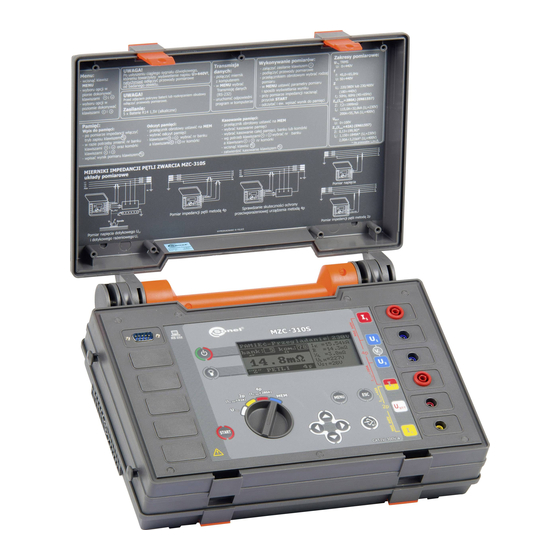
Fig.1. MZC-310S front panel layout 4.4.1 Terminals CAUTION! MZC-310S is designed to operate at rated phase voltages of 220V and 230V and inter- phase voltages of 380V and 400V. Applying voltages higher than those specified to any of the test terminals can damage the device. -
Page 11: Keyboard
5 Test terminal U Terminal to connect the voltage neutral cable N or the protective cable PE (PEN) in the four-pole meth- od of short-circuit loop impedance measurement or the cable to measure alternating voltage. 6 Test terminal U ST/T Terminal to connect the protective cable PE (PEN) in the function of touch voltage U measurement or an electrode (probe) in the touch shock voltage U... -
Page 12: Graphical Display Panel (Lcd)
14 Key Exit from selected option Return to the previous screen 15 Key Switching the LCD illumination on and off. Graphical Display Panel (LCD) Device overheating (symbol replaces “READY” flag) - Battery status Battery low – needs replacement. Sending results to the memory. -
Page 13: Buzzer
Text “READY” advising Length of measurement cables for “2p” about the capability Battery status to make the measurement Measurement function or the temperature excess symbol Main result or messages Current value of U and f or messages Fig. 4. Screen layout in short-circuit loop impedance measurement mode (main result only) Function Network rated voltage Bank and... -
Page 14: Test Leads
Cell, bank or the entire memory erasure confirmation Test Leads MZC-310S short-circuit loop meters using a 2p method are factory calibrated to compensate for the resistance of the proprietary test leads that are supplied in the following lengths: cable L: ... -
Page 15: Storage
WARNING: Connecting unsuitable or faulty cables can cause an electrical shock. Note: The manufacturer guarantees correct readings only if the original leads supplied with the device are used and if the correct length (for 2p method) has been selected in the MENU. Extension leads or third party cables can be a source of additional errors. -
Page 16: Operations
Operations You need to get familiar with this chapter as it describes test diagrams, testing methods and basic rules of interpreting obtained results. Preparing the Device For Work Before commencing the measurements: Make sure that the battery condition will allow you to complete the task ... -
Page 17: Power Supply Voltage Monitoring
Measurement results Fig.7. Battery charge indicator Battery Replacement MZC-310S meter is supplied with five R14 batteries (alkaline batteries are recommended) that should be placed in the battery compartment located in the bottom part of the meter’s housing. WARNING: Leaving the leads attached to the terminals can result in a life threatening electrocution. -
Page 18: Conditions For Performing Tests And Obtaining Correct Results
Fig. 8. Opening the battery compartment Conditions for Performing Tests and Obtaining Correct Results To start a test sequence a number of conditions have to be fulfilled. The device will automatically prevent a test from commencing (except for voltage measurement) if any of the conditions listed below is not satisfied: Displayed symbols Situation... -
Page 19: Device Connection Diagrams
Displayed symbols Situation Remarks and warning signals While measuring the loop imped- Text: Short circuit loop faulty! ance the fuse was burnt or another Two long beeps emergency situation in the current circuit occurred. Thermal protection prevents the A sound signal is produced when Displayed symbol 16 measurement. - Page 20 I max42A Fig.10. Measurement of impedance in working circuit (L-N) using two-pole method I max42A Fig.11. Measurement of impedance in protective circuit (L-PE) using two-pole method I max42A Fig.12. Measurement of impedance in working circuit (L-L) using two-pole method...
- Page 21 I max280A Fig.13. Measurement of impedance in working circuit (L-N) using four-pole method I max280A Fig.14. Measurement of impedance in protective circuit (L-PE) using four-pole method I max280A Fig.15. Measurement of impedance in working circuit (L-L) using four-pole method...
- Page 22 I max42A I max42A Fig.16. Verification of anti-shock protection reliability of appliance’s housing using two-pole method for: a) TN networks b) TT networks...
- Page 23 max280A max 280A Fig.17. Verification of the anti-shock protection reliability of appliance’s housing using four- pole method for: a) TN networks b) TT networks max280A (U ) ST/T Fig.18. Measurement of touch voltage U...
-
Page 24: Measurement Of Alternating Voltage
max280A (U ) ST/T Probe Fig.19. Measurement of shock voltage U Measurement of Alternating Voltage CAUTION! Applying voltage in excess of 440V to any of the test terminals may damage the device. To measure alternating voltage: Connect the test cables to sockets: 4 U and 5 U (Fig.9) ... -
Page 25: Measurement Of Network Voltage And Frequency
CAUTION! If the tested installation includes RCD circuit breakers, you should bridge them for the duration of the test. You should keep in mind however that doing so you modify the tested circuit and consequently the results can marginally differ from the expected results. Remember to remove any modifications of the installations that were introduced and check the functioning of the RCD circuit breakers. -
Page 26: Displaying All Measurement Results Or The Main Result Only
7.7.3 Displaying All Measurement Results Or The Main Result Only In order to choose between displaying all measurement results or the main result only (Z or I you need to: Press the key 13 Select Display settings In the item Results, select and store the option required (see section 7.10.3 MENU) 7.7.4 Displaying The Measurement Results In Terms of Impedance or Short- Circuit Current... -
Page 27: Measurement Of Touch Voltage U
7.7.5 Measurement of Touch Voltage U And Touch Shock Voltage U Note: Touch shock voltage U as measured by the meter applies to the network rated voltage for which the measurement was made. For other rated voltages the result displayed should be converted. -
Page 28: Results Display
In the item Cable 2p [m], select and save an appropriate value (see section 7.10.4 MENU) 7.7.7 Results Display If display of all results was selected, the short-circuit impedance Z or expected short-circuit cur- rent I is shown as the main result. On the right hand side of the screen the measurement components are displayed: ... -
Page 29: Measurement Of Earthing Resistances
Press the key 10 Measurement of Earthing Resistances MZC-310S can be used for rough measurements of earthing impedance and resistance. To do this, use the installation phase cable as an auxiliary voltage source – see Fig.22. The measurement result is the sum of resistances of the earth electrode, working grounding, source and phase cable, thus it is burdened with a positive error. -
Page 30: Saving The Measurement Results
If disconnection is not possible need to be used meter from MRU family. Saving the Measurement Results MZC-310S devices have a built-in memory for storing up to 990 results of short-circuit loop pa- rameters. A location in the memory where a single result is stored is called a memory cell. The whole memory is divided into 10 banks, each consisting of 99 cells. -
Page 31: Storing Measurement Results In The Memory
The results storage is not erased when the meter is switched off. The data can be therefore re- trieved at a later time or transferred to a computer. The address of the current cell or bank number does not change either. It is recommended to erase the memory after the data has been read or before making a new se- ries of measurements that can be stored to the same cells as the previous ones. -
Page 32: Memory Browsing
7.9.2 Memory Browsing In order to view the measurement results stored in the memory, the user should set the rotary switch 9 to the position MEM. Choose Review from the menu. The screen will display the contents of the recently filled cell (Fig.5). Using the keys the user can select the bank number he/she wishes to review, and using the keys the cell number. -
Page 33: Menu
After selecting YES, press the key 12 ; the screen will display a message: Deletion of the whole memory and a progress bar. When deletion is completed, a message will be displayed: Whole memory deleted! and the meter will produce three short beeps. In order to cancel the deletion, press the key 14 7.10 Menu The menu is available in any position of the rotary switch with the exception of MEM. -
Page 34: Loop Measurement Settings
Fig.26. MENU – Display settings 7.10.4 Loop Measurement Settings In this submenu (Fig.27) the following parameters can be set: network rated voltage U (220V or 230V) length of cables in the measurement of short-circuit loop parameters using a two-pole method (2p) ... -
Page 35: Upgrading The Software
The warranty does not cover any malfunctions of the device that result from incorrect applica- tion of this function. To update the software you need to: Download the software from the manufacturer’s web site (www.sonel.pl) Connect the meter to the PC ... -
Page 36: Information About The Manufacturer And The Software
The software package can be used to communicate with a range of instruments manufactured by SONEL S.A. that are equipped with an RS232 connection. Detailed information about the software is available from the manufacturer and the distributors. -
Page 37: Trouble Shooting
Trouble Shooting Warnings And Information Displayed By The Meter MZC-310S device displays warnings that can be related to either its functioning or to external con- ditions affecting the measurement processes. 8.1.1 Exceeding The Measurement Range Text displayed Audible signal Reason... -
Page 38: Cleaning And Maintenance
Symptom Reason Action The meter does not switch on with Batteries discharged or Make sure that the batteries are inserted incorrectly correctly inserted. Replace the the push-button 8 batteries. If the problem persists While measuring, the symbol 18 send the device to the service is displayed. -
Page 39: Appendices
11 Appendices 11.1 Technical Specifications The abbreviation „i.v.” in the definition of the basic error means the displayed value. Voltage Measurement (True RMS) Range Resolution Basic error (2% i.v. + 2 digits) 0...440V Frequency range: DC, 45...65Hz Input impedance of the voltmeter: 200k... - Page 40 Measurement of Short-Circuit Loop Using Standard Current (2p, I =42A) Measurement of short-circuit loop impedance Z Measurement range in accordance with IEC 61557 Test Lead Measurement Range Z 0.13…199.9 1.2m 0.15…199.9 0.19…199.9 0.25…199.9 Display range Z Range Resolution Basic Error...
-
Page 41: Manufacturer
Quality standard......development, design and manufacturing to ISO 9001 compliant q) The instrument meets the requirement of the IEC 61557 standard. 11.2 Manufacturer The manufacturer of the device provides all warranty and after-warranty repairs: SONEL S.A. ul. Wokulskiego 11 58-100 Świdnica Poland tel.
Need help?
Do you have a question about the MZC-310S and is the answer not in the manual?
Questions and answers