Advertisement
Quick Links
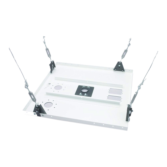
The CMA-450 Reinforcing Kit provides a sturdy support for LCD/DLP hanging brackets
(and certain other products) when installing these products in a suspended ceiling.
The Kit includes a 24 x 24 in. (610 x 610 mm) reinforcing plate that will be suspended
by four tie wires from the true ceiling above the suspended ceiling tiles. Turnbuckles
allow the installation to be fine-tuned.
The reinforcing plate can be installed in place of a standard 2 x 2 in. ceiling tile, or it
can be installed above the suspended ceiling.
Important Warnings and Precautions !
WARNING: A WARNING alerts you to the possibility of serious injury or death if you
do not follow the instructions.
CAUTION: A CAUTION alerts you to the possibility of damage or destruction of
equipment if you do not follow the corre-sponding instructions.
WARNING: Improper installation can result in serious personal injury! Make sure that
the ceiling structural mem-bers can support a redundant weight factor five times the
total weight of the equipment: if not, reinforce the ceiling before installing the
suspended ceiling kit.
WARNING: Be aware also of the potential for personal injury or damage to the unit
if it is not adequately mounted.
WARNING: The installer is responsible for verifying that the ceiling to which the
CMA-450's reinforcing plate is anchored will safely support the combined load of all
attached components or other equipment.
WARNING: The weight of the LCD/DLP projector must not exceed 250 lbs (113.4 kg),
the maximum load capacity of the reinforcing plate.
CAUTION: To avoid personal injury or damage to the suspended ceiling kit, be sure
that it is installed square and parallel in all dimensions. Avoid stressing the unit at any
time while you are installing it.
CAUTION: Check the unit for shipping damage before you begin the installation.
P
800 . 582 . 6480
F
877 . 894 . 6918
SUSPENDED CEILING TILE REINFORCING KIT
Before You Begin
CAUTION: To prevent damage to the Kit, which could affect or void the
Factory warranty, and to the equipment that will be attached to it,
thoroughly study all instructions and illustrations before you begin the
installation. Pay particular attention to the "Important Precautions" on
Page 1.
The ceiling tray is designed to fit within a 24 x 24 in. (610 x 610 mm) section of a
conventional suspended ceiling system. If mounted in a 2' X 2' suspended ceiling,
runners should have a "T" cross-section and a minimum height of 1.5 in. (38 mm). If
24 x 48 in. (610 x 1219 mm) ceiling tiles are used, cut one tile in half and add another
24-in. (610-mm) ceiling runner, to make a 24 x 24 in. section. If mounted above the
ceiling, the mount may be adjusted to fit anywhere in the 48" tile space.
If you have any questions about this installation, contact Chief Manufacturing at 1-
800-582-6480.
In certain installations, it may be easier to install the ceiling anchors (page 3) before
you attach the hanger brackets to the ceiling tray.
W
CHIEFMFG.COM
E
CHIEF@ CHIEFMFG.COM
Hanger brackets for
support wires and
turnbuckles
Adjustable bracket for
attaching LCD/DLP
mounting bracket
A
12800 HWY 13 S., STE. 500, SAVAGE, MN 55378
CMA-450
Knockouts for electrical outlet
boxes and antenna leads
Attachment point for safety
cable and clamp
1 OF 4
Advertisement

Related Manuals for CHIEF CMA-450


Summary of Contents for CHIEF CMA-450
- Page 1 WARNING: The installer is responsible for verifying that the ceiling to which the CMA-450’s reinforcing plate is anchored will safely support the combined load of all attached components or other equipment. WARNING: The weight of the LCD/DLP projector must not exceed 250 lbs (113.4 kg), the maximum load capacity of the reinforcing plate.
- Page 2 2 OF 4 SUSPENDED CEILING TILE REINFORCING KIT CMA-450 Contents Assembly Procedures TOOLS REQUIRED FOR INSTALLATION Attach the Hanger Brackets to the Cieling Tray ASSEMBLY PROCEDURES ATTACH THE HANGER BRACKETS TO THE CEILING TRAY 1. Using two 1/4” x 20 x 3/8” Phillips-head screws (B), attach four hanger brackets (D) ANCHOR THE TRAY TO THE CEILING to the four corners of the mounting plate bracket (A).
- Page 3 (G). Use 12-gauge annealed, steel, black wire. A longer safety cable (item H in parts on page 5) may also be required. Contact Chief Anchoring Procedure Manufacturing for assistance in determining your specific requirements.
- Page 4 4 OF 4 SUSPENDED CEILING TILE REINFORCING KIT CMA-450 Secure the Safety Cable See items M, N, P, Q WARNING: It is the responsibility of the installer to verify that the ceiling to which the Kit is anchored will safety support the combined load of all attached components and equipment.
Need help?
Do you have a question about the CMA-450 and is the answer not in the manual?
Questions and answers