Advertisement
Quick Links
Advertisement

Related Manuals for CHIEF CMA440


Summary of Contents for CHIEF CMA440
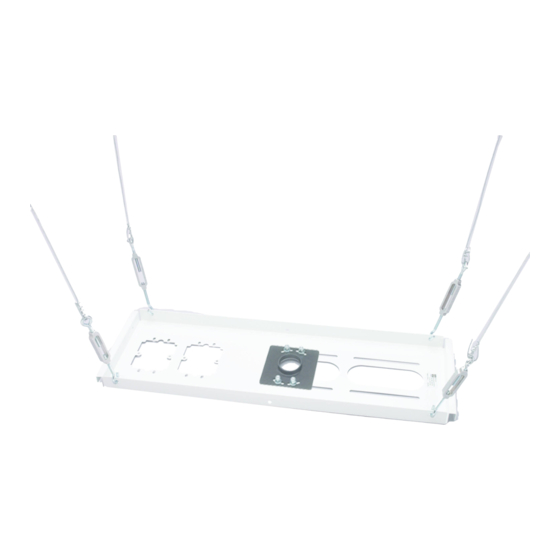
- Page 1 PDF provided by Conference Room AV Chief CMA440 Above Tile Suspended Ceiling Kit...
- Page 2 I N S T A L L A T I O N I N S T R U C T I O N S Above Tile Suspended Ceiling Kit CMA440...
-
Page 3: Important Safety Instructions
Do not use this product outdoors. ACCESSORY: AN ACCESSORY is the secondary Chief product which is attached to a primary Chief product, and may IMPORTANT ! : The CMA440 is designed for installation have a component attached or setting on it. - Page 4 Installation Instructions CMA440 DIMENSIONS 618.990 24.37 595.313 10.320 23.44 126.139 2.76 4.97 57.150 132.564 2.25 5.22 37.164 82.550 67.537 3.25 2.66 2.76 1.46 57.150 30.472 82.550 2.25 76.858 1.20 3.25 3.03 43.589 1.72 60.325 2.38 203.200 82.550 8.00 3.25 DIMENSIONS: [MILLIMETERS]...
- Page 5 CMA440 Installation Instructions LEGEND Tighten Fastener Pencil Mark Apretar elemento de fijación Marcar con lápiz Befestigungsteil festziehen Stiftmarkierung Apertar fixador Marcar com lápis Serrare il fissaggio Segno a matita Bevestiging vastdraaien Potloodmerkteken Serrez les fixations Marquage au crayon Measure Drill Hole...
-
Page 6: Tools Required For Installation
Installation Instructions CMA440 TOOLS REQUIRED FOR INSTALLATION 1/4" 5/32" 5/16" PARTS C (1) B (1) [14-gage, 20’ Support wire] [1/8" x 10’ Safety cable] A (1) [Ceiling tray] D (2) E (1) [Wire clamp] F (1) [1 1/2" NPT ring]... - Page 7 Reinforce the structure as required before installing the component. NOTE: The CMA440 is designed for installation on top of an existing suspended ceiling tile. The CMA440 can accommodate one 1-1/2" NPT or NPSM Figure 2 following ANSI/ASME B1.20.1 (Schedule 40, 0.154"...
- Page 8 Installation Instructions CMA440 Mark the following locations on ceiling tile with pencil (See Figure 4): Standard (USA/SAE) Extension column hole OPTIONAL: Electrical cutout (H) x 4 2" (51mm) (Ceiling track) Figure 5 Figure 4 Examine ceiling structure (concrete, steel truss, or wood)
- Page 9 Tap anchor (L) into each hole to a depth of at least 1" anchoring wire. Use 14-gauge soft galvanized wire. A (25.4mm). (See Figure 8) longer safety cable may also be required. Contact Chief Manufacturing for assistance in determining your specific requirements. Wood Ceiling Structure WARNING: Anchors must be installed into wood with a minimum thickness of 1-1/2"...
- Page 10 Installation Instructions CMA440 Steel Truss Ceiling Structure Insert corresponding support wire (C) through eye in each of the four turnbuckles (N). Pull wire tight and twist back Route end of support wire (C) over truss at marked wire around itself at least 4 complete turns, then thread loose anchor support location.
-
Page 11: Safety Cable Installation
CMA440 Installation Instructions SAFETY CABLE INSTALLATION Attach safety cable (B) to steel truss ceiling structure at marked location. NOTE: If no suitable steel truss structure exists, install concrete anchor (Simpson Tie-Wire concrete anchor #TWD25112, not included) or wood eye lag as required (hardware not included) per manufacturer’s installation... - Page 12 It is the installer’s responsibility to make sure the combined weight of all components attached to the CMA440 does not exceed 50 lbs (22.68 kg). Install 1-1/2" NPT or NPSM following ANSI/ASME B1.20.1 (Schedule 40, 0.154"...
- Page 13 A 6436 City West Parkway, Eden Prairie, MN 55344 P 800.582.6480 / 952.225.6000 F 877.894.6918 / 952.894.6918 Europe A Franklinstraat 14, 6003 DK Weert, Netherlands Chief, a products division of P +31 (0) 495 580 852 Milestone AV Technologies F +31 (0) 495 580 845 Asia Pacific A Office No.
Need help?
Do you have a question about the CMA440 and is the answer not in the manual?
Questions and answers