Table of Contents
Advertisement
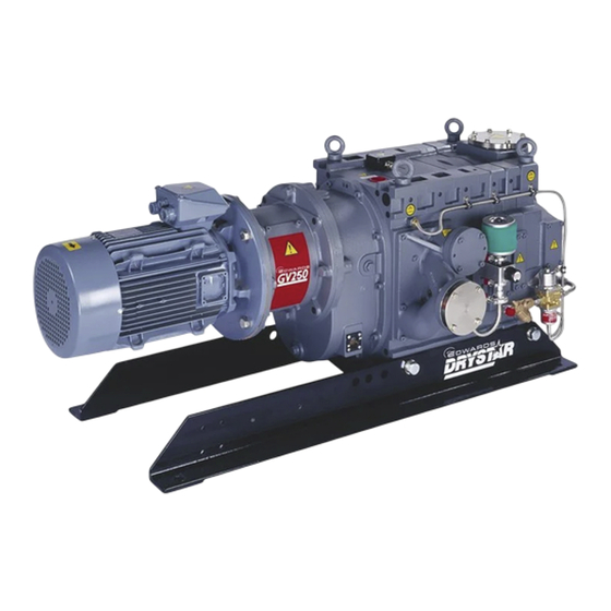
Description
GV250 Dry Vacuum Pump, 380/400/415 V, 50 Hz
GV250 Dry Vacuum Pump, 230/460 V, 60 Hz
GV250 Bareshaft Dry Vacuum Pump, 50/60 Hz
GV250F Bareshaft Dry Vacuum Pump, 50/60 Hz
Instruction Manual
GV Dry Vacuum Pumps
Item
Description
Number
A705-61-900 GV400 Dry Vacuum Pump, 380/400/415 V, 50 Hz
A705-61-908 GV400 Dry Vacuum Pump, 230/460 V, 60 Hz
A705-61-985 GV400 Bareshaft Dry Vacuum Pump, 50 Hz
A705-15-985 GV400 Bareshaft Dry Vacuum Pump, 60 Hz
GV400F Bareshaft Dry Vacuum Pump, 50 Hz
GV400F Bareshaft Dry Vacuum Pump, 60 Hz
A705-61-880
Issue M Original
Item
Number
A706-61-900
A707-61-908
A706-11-985
A707-11-986
A706-15-985
A707-15-986
Advertisement
Table of Contents

Subscribe to Our Youtube Channel
Related Manuals for Edwards GV Series


Summary of Contents for Edwards GV Series
- Page 1 A705-61-880 Issue M Original Instruction Manual GV Dry Vacuum Pumps Item Item Description Description Number Number GV250 Dry Vacuum Pump, 380/400/415 V, 50 Hz A705-61-900 GV400 Dry Vacuum Pump, 380/400/415 V, 50 Hz A706-61-900 GV250 Dry Vacuum Pump, 230/460 V, 60 Hz A705-61-908 GV400 Dry Vacuum Pump, 230/460 V, 60 Hz A707-61-908 GV250 Bareshaft Dry Vacuum Pump, 50/60 Hz...
-
Page 2: Declaration Of Conformity
Declaration of Conformity Edwards, Manor Royal, Crawley, West Sussex, RH10 9LW, UK declare under our sole responsibility, as manufacturer and person within the EU authorised to assemble the technical file, that the product(s) GV250 Dry Vacuum Pump, 380/400/415 V, 50 Hz... -
Page 3: Table Of Contents
Allow the pump to warm up ..................25 Check the purge pressures and flows ................26 Shut down the pump ....................26 © Edwards Limited 2012. All rights reserved. Page i Edwards and the Edwards logo are trademarks of Edwards Limited. - Page 4 7.4.5 Other accessories .......................48 Index ....................49 For return of equipment, complete the HS Forms at the end of this manual. Page ii © Edwards Limited 2012. All rights reserved. Edwards and the Edwards logo are trademarks of Edwards Limited.
- Page 5 Motor relubrication grease required ................. 42 Motor bearing relubrication intervals ................42 Fault finding ......................43 Spares Item Numbers ....................48 Accessory Item Numbers ....................48 © Edwards Limited 2012. All rights reserved. Page iii Edwards and the Edwards logo are trademarks of Edwards Limited.
- Page 6 A705-61-880 Issue M This page has been intentionally left blank. Page iv © Edwards Limited 2012. All rights reserved. Edwards and the Edwards logo are trademarks of Edwards Limited.
-
Page 7: Introduction
Introduction Scope and definitions This manual provides installation, operation and maintenance instructions for the Edwards GV Dry Vacuum Pumps (abbreviated to GV pump(s) or pump(s) in the remainder of this manual). You must use the GV pumps as specified in this manual. - Page 8 19. Motor cooling-fan 9. Frame 20. Oil drain-plug 10. Gas-ballast flow valve 21. Oil filler-plug 11. Exhaust-purge port (blanked) 22. Shaft-seals purge inlet Page 2 © Edwards Limited 2012. All rights reserved. Edwards and the Edwards logo are trademarks of Edwards Limited.
-
Page 9: Gas System
10. A coupling hub (14) is fitted to the pump shaft (9) and a drive hub (16) is fitted to the motor shaft (18). A coupling insert (15) fits between the coupling and drive hubs. © Edwards Limited 2012. All rights reserved. Page 3 Edwards and the Edwards logo are trademarks of Edwards Limited. -
Page 10: Liquid Pumping Capability
The GV pump can survive the ingress of some liquid (after a process failure condition, for example) without damage, however the pump is not suitable for continuous pumping of liquids. If you want to continuously pump a liquid stream, contact your supplier or Edwards for advice. Safe area operation You must not use the GV pump in the following hazardous areas: Zone 0, Zone 1 or Zone 2 (gases), or Zone Z (10) or Zone Y (11) (dusts), as classified by European authorities. -
Page 11: Technical Data
Typical pump rotation speed 50 Hz electrical supply 2940 r min 2940 r min 60 Hz electrical supply 3580 r min 3580 r min © Edwards Limited 2012. All rights reserved. Page 5 Edwards and the Edwards logo are trademarks of Edwards Limited. -
Page 12: Mechanical Data
Motor flange PCD (60 Hz) 12.5 inch 12.5 inch Motor spigot (50 Hz) 250 mm 250 mm Motor spigot (60 Hz) 11 inch 11 inch Page 6 © Edwards Limited 2012. All rights reserved. Edwards and the Edwards logo are trademarks of Edwards Limited. -
Page 13: Electrical Data (For Edwards Supplied Motors)
Pump at ultimate vacuum with a cooling-water supply temperature of 20 °C (68 °F) and an ambient temperature of 20 °C (68 °F). © Edwards Limited 2012. All rights reserved. Page 7 Edwards and the Edwards logo are trademarks of Edwards Limited. -
Page 14: Lubrication Data
Lubrication data WARNING Particular caution should be exercised when working with Fomblin oil that may have been exposed to temperatures above 260 °C. Refer to the Edwards Materials Data Sheets for detailed information. Note: Edwards Material Safety Data Sheets for the recommended oil and grease specified in... -
Page 15: Pump Dimensions
GV400 40.16 15.91 5.83 22.83 12.4 39.37 26.22 7.09 14.84 18.11 24.88 0.52 Dependent on motor fitted i.e. Bareshaft pump supplied © Edwards Limited 2012. All rights reserved. Page 9 Edwards and the Edwards logo are trademarks of Edwards Limited. - Page 16 A705-61-880 Issue M This page has been intentionally left blank. Page 10 © Edwards Limited 2012. All rights reserved. Edwards and the Edwards logo are trademarks of Edwards Limited.
-
Page 17: Installation
WARNING Particular caution should be exercised when working with Fomblin oil that may have been exposed to temperatures above 260 °C. Refer to the Edwards Materials Data Sheets for detailed information. A suitably trained and supervised technician must install the pump. -
Page 18: Unpack And Inspect
Ensure that debris (such as weld slag) cannot get into the pump during operation. If necessary, contact Edwards or your supplier for advice on inlet isolation-valves, outlet check-valves or other components suitable for your application and system design. Unpack and inspect WARNING Use suitable lifting equipment to move the pump. -
Page 19: Locate The Pump
3.6.2. However, you must refer to the motor manual supplied with your pump for detailed instructions on how to connect your electrical supply to the pump-motor. © Edwards Limited 2012. All rights reserved. Page 13 Edwards and the Edwards logo are trademarks of Edwards Limited. -
Page 20: Connect The Electrical Supply To The Pump-Motor
5. If you will fit separate thermistors cable continue at Step 6 below, otherwise continue at Step 3 of Section 3.6.3. 6. Tighten the cable-gland nut strain-relief screws 7. Continue at Section 3.6.3 to connect the thermistor outputs Page 14 © Edwards Limited 2012. All rights reserved. Edwards and the Edwards logo are trademarks of Edwards Limited. -
Page 21: Schematic Diagram Of The Recommended Electrical Connections
7. Start control Location Size 8. Shut-down thermal snap-switch Thermal snap-switch box M4 tapped hole 9. Inlet-valve control solenoid (optional) 10. Contactor Pump-motor © Edwards Limited 2012. All rights reserved. Page 15 Edwards and the Edwards logo are trademarks of Edwards Limited. -
Page 22: Connect The Thermistor Outputs
You must connect the output of the shut-down thermal snap-switch to the electrical-overload control-loop of your contactor, so that the contactor will automatically switch off the pump if it is too hot: refer to Figure Page 16 © Edwards Limited 2012. All rights reserved. Edwards and the Edwards logo are trademarks of Edwards Limited. -
Page 23: Check The Direction Of Rotation
1. Refit the coupling cover (15) and secure with the four bolts. Tighten the bolts to a torque between 3 and 5 Nm (2.2 and 3.7 lbf ft). © Edwards Limited 2012. All rights reserved. Page 17 Edwards and the Edwards logo are trademarks of Edwards Limited. -
Page 24: Fit A Mechanical Booster Pump (Optional)
5. Cable-gland 6. Warning wires 7. Spade terminals 8. Warning thermal snap-switch 9. Shut-down thermal snap-switch 10. Spade terminals 11. Shut-down wires Page 18 © Edwards Limited 2012. All rights reserved. Edwards and the Edwards logo are trademarks of Edwards Limited. -
Page 25: Connect The Cooling-Water Supply
Use the procedures in Section 3.10.2 and 3.10.3 to connect nitrogen supplies to the shaft-seals purge inlet and to the gas-ballast system. © Edwards Limited 2012. All rights reserved. Page 19 Edwards and the Edwards logo are trademarks of Edwards Limited. -
Page 26: Connect The Shaft-Seals Purge Air Or Nitrogen Supply
2. Use the clamp (4) and trapped ‘O’ ring (3) to connect your nitrogen supply pipeline to the gas-ballast flow valve (5). Page 20 © Edwards Limited 2012. All rights reserved. Edwards and the Edwards logo are trademarks of Edwards Limited. -
Page 27: Connect The Pump-Inlet
If required, you can adapt the blanking-plate removed in Step 1 above to fit your exhaust pipeline: drill a suitable size hole in the centre of the blanking-plate, then weld the blanking-plate to your pipeline. © Edwards Limited 2012. All rights reserved. Page 21 Edwards and the Edwards logo are trademarks of Edwards Limited. -
Page 28: Leak Test The System
9. Turn off the pump, the cooling-water supply, the shaft-seals air or nitrogen purge supply and the gas-ballast nitrogen supply (if fitted). Page 22 © Edwards Limited 2012. All rights reserved. Edwards and the Edwards logo are trademarks of Edwards Limited. -
Page 29: Exploded View Of The Gas-Ballast Assembly
8. Co-Seal 3. Co-Seal 9. Clamp 4. Clamp 10. Flap valve 5. Gas-ballast flow valve 11. Elbow 6. Clamp and Co-Seal © Edwards Limited 2012. All rights reserved. Page 23 Edwards and the Edwards logo are trademarks of Edwards Limited. - Page 30 A705-61-880 Issue M This page has been intentionally left blank. Page 24 © Edwards Limited 2012. All rights reserved. Edwards and the Edwards logo are trademarks of Edwards Limited.
-
Page 31: Operation
2.5 x 10 Pa, 37.5 to 188 Torr), warm-up time can be reduced to as little as 10 minutes. © Edwards Limited 2012. All rights reserved. Page 25 Edwards and the Edwards logo are trademarks of Edwards Limited. -
Page 32: Check The Purge Pressures And Flows
5. When the pump has cooled down, turn off the cooling-water supply. 6. Switch off the shaft-seals purge nitrogen supply (if fitted). Page 26 © Edwards Limited 2012. All rights reserved. Edwards and the Edwards logo are trademarks of Edwards Limited. -
Page 33: Maintenance
260 °C (500 °F) and above. These breakdown products are very dangerous. The pump may have overheated if it was misused, if it malfunctioned, or if it was in a fire. Edwards Material Safety Data Sheets for the fluorinated materials used in the pump are available on request: contact your supplier or Edwards. -
Page 34: Check The Gearbox Oil-Level And Fill The Gearbox With Oil (If Necessary)
WARNING Particular caution should be exercised when working with Fomblin oil that may have been exposed to temperatures above 260 °C. Refer to the Edwards Materials Data Sheets for detailed information. Page 28 © Edwards Limited 2012. All rights reserved. -
Page 35: Inspect The Gas Ballast System
If you need to pour oil into the gearbox frequently, or if there is a sudden loss of a large amount of oil, the pump may be faulty: shut down the pump and contact your supplier or Edwards. Figure 1 shows the locations of the two oil-level sight-glasses on the pump. -
Page 36: Inspect The Interstage Relief Valve And Replace The Hinge Bushes, Valve Flap And Valve 'O' Ring
If you use a cleaning solution, ensure that all of the solution is removed before you fit the new interstage relief valve components. 6. Inspect the 'O' rings (8, 5, 4) and, if necessary, fit new 'O' rings. Page 30 © Edwards Limited 2012. All rights reserved. Edwards and the Edwards logo are trademarks of Edwards Limited. -
Page 37: Exploded View Of The Interstage Relief Valve
3. Exhaust manifold 9. Retainer 4. ‘O’ ring 10. Jacking hole 5. 'O' ring 11. Bolt (4 off) 6. Valve ‘O’ ring © Edwards Limited 2012. All rights reserved. Page 31 Edwards and the Edwards logo are trademarks of Edwards Limited. -
Page 38: Change The Gearbox Oil And Clean The Oil-Level Sight-Glasses
(Fomblin) oil, you cannot simply flush the pump with new PFPE oil. You must return the pump to a Edwards Service Centre for overhaul and cleaning by qualified Edwards service engineers. The change in oil type requires a complete strip down of the pump, and thorough cleaning of all parts, so that all traces of hydrocarbon oil are removed. -
Page 39: Relubricate The High-Vacuum Bearings
9. Repeat Step 8 to refit the bearing cap (6) on the driven rotor shaft. 10. Dispose of the old grease safely: refer to Section 6.2. © Edwards Limited 2012. All rights reserved. Page 33 Edwards and the Edwards logo are trademarks of Edwards Limited. -
Page 40: Oil-Level Sight-Glass And Oil Filler And Drain Ports
4. Bonded seal 11. Screws (4 off) 5. Oil drain-port 12. Oil filler-plug 6. Compression ring 13. Bonded seal 7. ‘O’ ring Page 34 © Edwards Limited 2012. All rights reserved. Edwards and the Edwards logo are trademarks of Edwards Limited. - Page 41 6. Driven shaft bearing cap 3. Bearing cap ‘O’ ring 7. Correct direction of rotation 4. Drive shaft bearing cap 8. Bearing carrier bolt © Edwards Limited 2012. All rights reserved. Page 35 Edwards and the Edwards logo are trademarks of Edwards Limited.
-
Page 42: Flush The Cooling Jacket
If you use a cleaning solution, ensure that all of the solution is removed before you fit the new interstage relief valve. Page 36 © Edwards Limited 2012. All rights reserved. Edwards and the Edwards logo are trademarks of Edwards Limited. -
Page 43: Replace The Pump-Motor
If you have supplied your own pump - motor you are responsible for its maintenance which must be carried out in accordance with the motor manufacturer’s recommendations. If the motor is a Edwards supplied product, please consult the supplied literature or contact Edwards for further information. -
Page 44: Fit The New Pump-Motor
(16) and coupling hub (14) are parallel, and the gap between the teeth on the two hubs is 2.5 ± 1 mm. Page 38 © Edwards Limited 2012. All rights reserved. Edwards and the Edwards logo are trademarks of Edwards Limited. - Page 45 25. Use the four bolts (13) to secure the other coupling covers (12) to the coupling housing (7). Tighten the bolts to a torque between 3 and 5 Nm (2.2 and 3.7 lbf ft). © Edwards Limited 2012. All rights reserved. Page 39 Edwards and the Edwards logo are trademarks of Edwards Limited.
-
Page 46: Exploded View Of The Pump-Motor, Coupling Drive And Coupling Housing
13. Bolt 14. Coupling hub 15. Coupling insert 16. Drive hub 17. Holding ring 18. Motor shaft 19. Pump-motor 20. Gap Page 40 © Edwards Limited 2012. All rights reserved. Edwards and the Edwards logo are trademarks of Edwards Limited. -
Page 47: Replace The Coupling Insert
Only use approved procedures to dismantle and reassemble the motor, and to relubricate the motor bearings. Edwards do not supply motor bearing grease. We recommend that you use Esso Unirex N3 grease to relubricate 50 Hz motor bearings, and Chevron SRI No. 2 or Shell Oil Dolium-R to relubricate the 60 Hz motor bearings. -
Page 48: Relubrication Intervals
Overhaul the pump We recommend that the pump is given a major overhaul every three years. Such an overhaul is outside the scope of this manual and should be done by qualified Edwards service personnel: contact your supplier or Edwards. Page 42 ©... -
Page 49: Fault Finding
200 to 1000 mbar (2.0 x 10 to 1 x 10 150 to 750 Torr) © Edwards Limited 2012. All rights reserved. Page 43 Edwards and the Edwards logo are trademarks of Edwards Limited. - Page 50 If you cannot rectify a problem, or if you cannot identify the cause of a problem, contact your supplier or Edwards for advice. Page 44 © Edwards Limited 2012. All rights reserved. Edwards and the Edwards logo are trademarks of Edwards Limited.
-
Page 51: Storage And Disposal
Fluoroelastomers which may have decomposed as the result of being subjected to high temperatures. Components and oil which have been contaminated with dangerous process substances. © Edwards Limited 2012. All rights reserved. Page 45 Edwards and the Edwards logo are trademarks of Edwards Limited. - Page 52 A705-61-880 Issue M This page has been intentionally left blank. Page 46 © Edwards Limited 2012. All rights reserved. Edwards and the Edwards logo are trademarks of Edwards Limited.
-
Page 53: Spares, Service And Accessories
The majority of these centres employ Service Engineers who have undergone comprehensive Edwards training courses. Order spare parts and accessories from your nearest Edwards company or distributor. When you order, state for each part required: Model and Item Number of your equipment ... -
Page 54: Indirect Cooling Kits
Kit with TCV (Thermostatic Control Valve) when you want to control the operating temperature of the GV pump. 7.4.5 Other accessories A number of other accessories are available for the GV pumps, as listed below; contact your supplier or Edwards for details of these accessories: Acoustic enclosure for the GV pump. -
Page 55: Index
WARNINGS ..........1 Leak test the system ........22 Liquid pumping capability ........ 4 Locate the pump ..........13 Lubrication data ........... 8 © Edwards Limited 2012. All rights reserved. Page 49 Edwards and the Edwards logo are trademarks of Edwards Limited. - Page 56 A705-61-880 Issue M This page has been intentionally left blank. Page 50 © Edwards Limited 2012. All rights reserved. Edwards and the Edwards logo are trademarks of Edwards Limited.
Need help?
Do you have a question about the GV Series and is the answer not in the manual?
Questions and answers