Hobo RX3000 Series Manual
Remote monitoring station
Hide thumbs
Also See for RX3000 Series:
- Manual (33 pages) ,
- Technical manual (6 pages) ,
- Quick start quide (2 pages)
Table of Contents
Advertisement
Quick Links
HOBO® RX3000 Remote Monitoring Station Manual
HOBO RX3000 Remote
Monitoring Station
Models: RX3001-00-01 Ethernet
RX3002-00-01 Wi-Fi
RX3003-00-01 Cellular
RX3004-00-01 Cellular 4G
Included Items:
• Two plates for cable access
openings with eight
thumbscrews and one wrench
• Two rubber cable channels
• Rubber plugs
• Grease packet
• Two mounting plates with
four screws
• Grounding wire
• Two U-bolts
Required Items:
• HOBOlink
• HOBOware
®
3.7.2 or later
with USB cable for RX3002 Wi-
Fi models (optional for
RX3001, RX3003, and RX3004
models)
• AC adapter (AC-U30) or solar
panel (SOLAR-xW)
Optional Items:
• Smart sensors
• Analog sensor module
(RXMOD-A1)
• Relay module (RXMOD-R1)
• RXW Manager (RXMOD-RXW-
xxx) and RXW motes
• Water level sensor module
(RXMOD-W1) with water level
sensor (MX2001-0x-S or
MX2001-0x-Ti-S) and cable
(CABLE-RWLMOD-xxx)
• External DC power cable
(CABLE-RX-PWR)
• Tripod kit (M-TPA or M-TPB)
• Guy wire kit (M-GWA)
• 1/2 inch stake kit (M-SKA)
• Grounding kit (M-GKA),
required if using wind speed
or wind direction smart sensor
Sensors, modules, and
accessories are available at
www.onsetcomp.com.
18255-N
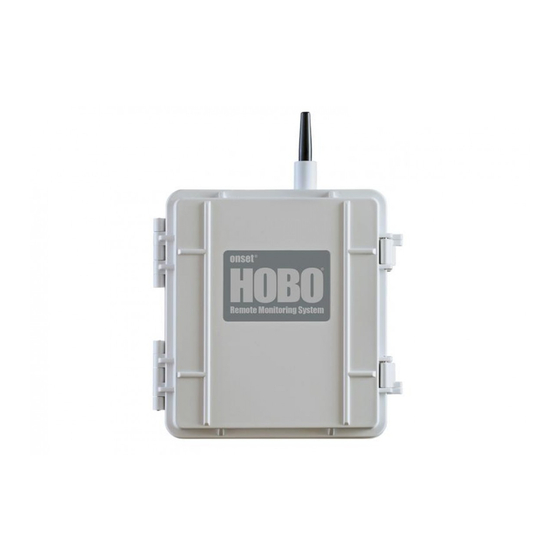
The HOBO RX3000 Remote Monitoring Station provides continuous logging for a broad range of
energy and weather monitoring applications with up to ten smart sensors, optional analog sensor,
water level sensor, and relay modules, and wireless sensor motes. Data from the RX3000 station is
transferred at regular connection intervals to HOBOlink® web-based software where you can
check the latest conditions, view graphs, configure sensors and alarms, set up a dashboard,
download your data, or schedule data delivery via email or FTP. Inside its weatherproof enclosure,
this durable station has a built-in LCD screen to check the current system configuration and status,
start and stop logging, add and remove smart sensors, and connect to HOBOlink on demand. Up
to three individual relays can be activated on the optional relay module while the optional analog
module has four analog inputs that support excitation power, scaling, and statistics
measurements. An optional RXW Manager module is also available for the station to set up the
HOBOnet Wireless Sensor Network, which can support up to 50 motes. All easy-to-install modules
can be configured with HOBOlink.
Specifications
Operating Range
Smart Sensor Connectors
Smart Sensor Network Cable
Length
Smart Sensor Data Channels
Module Slots
Logging Rate
Time Accuracy
Battery Type/Power Source
Rechargeable Battery
Service Life
Memory
Alarm Notification Latency
Enclosure Access
LCD
Materials
Size
Weight
Mounting
Environmental Rating
-40° to 60°C (-40° to 140°F); no remote communications for battery
voltage less than 3.9 V DC
10
100 m (328 ft) maximum
Maximum of 15 (some smart sensors use more than one data channel;
see sensor manual for details)
2
1 second (RX3001 and RX3002) or 1 minute (RX3003 and RX3004) to 18
hours
±8 seconds per month in 0° to 40°C (32°F to 104°F) range;
±30 seconds per month in -40° to 60°C (-40° to 140°F) range
4 Volt, 10 AHr, rechargeable sealed lead-acid; external power required
using one of these options: AC power adapter (AC-U30), solar panel
(SOLAR-xW), or external power source 5 V DC to 17 V DC with external
DC power cable (CABLE-RX-PWR)
Typical 3–5 years when operated in the temperature range -20° to 40°C
(-4°F to 104°F); operation outside this range will reduce the battery
service life
32 MB, 2 million measurements, continuous logging
Logging interval plus 2–4 minutes, typical
Hinged door secured by two latches with eyelets for use with user-
supplied padlocks
LCD is visible from 0° to 50°C (32° to 122°F); the LCD may react slowly
or go blank in temperatures outside this range
Outer enclosure: Polycarbonate/PBT blend with stainless steel hinge
pins and brass inserts; Inner enclosure: Polycarbonate; Gaskets:
Silicone rubber; Cable channel: EPDM rubber; Cable opening cover:
Aluminum with ABS plastic thumb screws; U-Bolts: Steel with zinc
dichromate finish
18.6 x 18.1 x 11.8 cm (7.3 x 7.1 x 4.7 in.); see diagrams on next page
2.2 kg (4.85 lb)
3.8 cm (1.5 inch) mast or wall mount
Weatherproof enclosure, NEMA 4X (requires proper installation of
cable channel system)
The CE Marking identifies this product as complying with all relevant
directives in the European Union (EU)
See last page
RX3002: FCC ID R68XPICOW, IC ID 3867A-XPICOW
RX3003: FCC ID QIPEHS6, IC ID 7830A-EHS6; approved for use in
Taiwan and Japan
RX3004: FCC ID QIPPLS62-W, IC ID:7830A-PLS62W
Advertisement
Table of Contents

Related Manuals for Hobo RX3000 Series


Summary of Contents for Hobo RX3000 Series
-
Page 1: Specifications
HOBO® RX3000 Remote Monitoring Station Manual The HOBO RX3000 Remote Monitoring Station provides continuous logging for a broad range of energy and weather monitoring applications with up to ten smart sensors, optional analog sensor, water level sensor, and relay modules, and wireless sensor motes. Data from the RX3000 station is transferred at regular connection intervals to HOBOlink®... -
Page 2: Table Of Contents
HOBO RX3000 Remote Monitoring Station Manual Table of Contents Setting up a Water Level Channel ............ 19 Specifications ..................1 Setting up a Water Flow Channel for a V-Notch Weir ...... 20 Module Specifications ................3 Setting up a Water Flow Channel for a Rectangular Weir ....21 Device Components and Operation ............ -
Page 3: Module Specifications
HOBO RX3000 Remote Monitoring Station Manual Module Specifications Optional Analog Sensor Module (RXMOD-A1) Input Channels Four, single-ended, in addition to smart sensor data channels Measurement Range and 0–25.6 mA DC, ±5 µA ± 0.15% of reading Accuracy 0–2.5 V DC, ±0.25 mV ±0.2% of reading 0–5 V DC, ±0.25 mV ±0.2% of reading... - Page 4 HOBO RX3000 Remote Monitoring Station Manual Module Specifications (continued) Optional Water Level Sensor Module (RXMOD-W1) Pressure (Absolute) and Water Level Measurements MX2001-01-S and MX2001-01-Ti-S Operation Range 0 to 207 kPa (0 to 30 psia); approximately 0 to 9 m (0 to 30 ft) of...
- Page 5 HOBO RX3000 Remote Monitoring Station Manual Module Specifications (continued) Water Level Sensor and Cable Dimensions Sensor (MX2001-0x-S and MX2001-0x-Ti-S): 2.54 cm (1.0 inches) diameter, 9.91 cm (3.9 inches) length ±0.03 ±0.01 Cable (CABLE-RWLMOD-xxx): 0.47 cm (0.185 inches diameter, 0.2 to 400 m (0.65 to 1,312 ft) length Note: The length of the water level logger cable can vary -0% to +3% +10 cm (3.9 inches) from the length ordered.
-
Page 6: Device Components And Operation
HOBO RX3000 Remote Monitoring Station Manual Device Components and Operation Antenna Connect/ Start/ (RX3003) Search Stop Select Station Door Button Button Button LCD Screen SIM Card (RX3003) or Micro SIM Card (RX3004) Vent Smart Sensor Grounding USB Port Module Slots... -
Page 7: Lcd Operation
HOBO RX3000 Remote Monitoring Station Manual LCD Operation This example shows all symbols illuminated on the LCD screen with an overview of what each section of the LCD represents. Refer to the table below for details about each section and associated symbols. - Page 8 HOBO RX3000 Remote Monitoring Station Manual This part of the LCD shows the number of channels and other information about each module. It also shows general device Channel and information. Press the Select button to scroll through four screens: the main screen, smart sensors screen, Module 1, and Device Module 2 screens.
-
Page 9: Setting Up The Station
HOBO RX3000 Remote Monitoring Station Manual Notes on LCD Operation: If you installed an RXW Manager module: • The LCD will turn off after 5 minutes of inactivity. Press Plug the cable from the RXW Manager mote into the jack on the module, making sure the cable is inserted through the any button to turn the LCD back on. -
Page 10: Check And Configure Device Communications
HOBO RX3000 Remote Monitoring Station Manual c. Once the battery cable is plugged in, “Initializing d. In the RX Station Manager, click the Actions button and System” will flash on the LCD. A checkmark appears next select Network Access. to “System” after the station initialization is complete. -
Page 11: Plug In And Search For Any Smart Sensors
HOBO RX3000 Remote Monitoring Station Manual e. The station uses DHCP by default. If your network uses b. Press the Select button to view the smart sensors on the DHCP, skip this step. LCD and then press the Search button (the magnifying glass icon should be visible as in the following example). -
Page 12: Connect Analog Sensors, Relay Devices, Or Water Level Sensors
HOBO RX3000 Remote Monitoring Station Manual c. Watch the mote LCD during the process of joining the To connect analog sensors: network. You can connect a two- or three-wire sensor or transducer to one of the four terminals in the analog module. -
Page 13: Connect To Hobolink
HOBO RX3000 Remote Monitoring Station Manual Relay Module Pinout Table rubber plugs from the channel kit included with the station to fill any remaining large and small holes. Pin Desc. Pin Desc. Pin Desc. RELAY-1 RELAY-2 RELAY-3 Insert the thin part of the plug into the hole and push... - Page 14 HOBO RX3000 Remote Monitoring Station Manual Note: Click Save or Next in any screen to save your changes. Tip: When a sampling interval is configured, the station You will lose any changes made if you click Back without will take multiple measurements within a given logging clicking Next or Save first.
- Page 15 HOBO RX3000 Remote Monitoring Station Manual a. Click Water Level Sensors Logging from the b. Select the logging interval to be used for all wireless Configuration menu. sensors, which can be different than the one used for smart sensors and analog sensors (if applicable).
- Page 16 HOBO RX3000 Remote Monitoring Station Manual • With continuous, the station supplies constant i. To set up scaling for the wireless sensor, click the Enable Scaling checkbox and fill in the Scaled Units, Multiplier, excitation power to the sensor for the entire duration Offset, and Scaled Measurement Type.
-
Page 17: Start Logging
HOBO RX3000 Remote Monitoring Station Manual b. Type a label and select Open or Closed for the Normal Important: See Deploying and Mounting the Station for Relay State. The label can be used to show what Open installation steps and other deployment guidelines. If using... -
Page 18: Viewing Data In Hobolink
HOBO RX3000 Remote Monitoring Station Manual g. Click Save. 2. Click Create New Export. 3. Follow the instructions on the screen to select the name, Water Flow Configuration format, time zone, and time frame, and then the devices a. Select Water Flow from the Configuration menu. -
Page 19: Sensor Alarms
HOBO RX3000 Remote Monitoring Station Manual 4. For Battery Low and Sensor Failure alarms: 10. Add any optional notes for this alarm. a. Under Device, select the Battery Low and/or Sensor 11. Click Save. Changes will take effect the next time the station Failure checkboxes. -
Page 20: Setting Up A Water Flow Channel For A V-Notch Weir
HOBO RX3000 Remote Monitoring Station Manual 4. Click the checkbox to Enable Graph and type a label the reference water level you entered for the water level (optional). channel (meters or feet). 5. Enter the reference water level and date and time the reading was taken. -
Page 21: Setting Up A Water Flow Channel For A Rectangular Weir
HOBO RX3000 Remote Monitoring Station Manual 3. Click the checkbox to Enable Channel. The HOBOlink water flow calculations for a rectangular weir assume the following: 4. Click the checkbox to Enable Graph and type a label • The range for the weir opening width is 0.15 to 6 m (0.5 to (optional). -
Page 22: Setting Up A Water Flow Channel For A Trapezoidal Weir
HOBO RX3000 Remote Monitoring Station Manual 10. Click Save. Important: Make sure the station has started logging and you Water flow will be calculated starting with the next connection have configured the water level channel with a reference level to HOBOlink. -
Page 23: Setting Up A Water Flow Channel For A Stage-Discharge Table
HOBO RX3000 Remote Monitoring Station Manual • If the reference point is below the water level, then enter Important: Make sure the station has started logging and you a positive number. have configured the water level channel with a reference level 8. -
Page 24: Starting And Stopping Logging
HOBO RX3000 Remote Monitoring Station Manual common equation used for stage-discharge curves is logging interval specified for smart sensors, wireless sensors Manning’s Equation. and analog sensors (if applicable). The station is stopped o Once you have selected the type of equation to use,... -
Page 25: Adding Or Removing Modules
HOBO RX3000 Remote Monitoring Station Manual • Add any wireless motes (see Adding or Removing channel, and reinstall the plates. See Installing the Weatherproof Rubber Cable Channel and Covers for details. Motes). • If you added a water level sensor module, be sure to 9. -
Page 26: Adding Or Removing Motes
The green LED blinks quickly while the mote searches for a HOBO RXW Manager is installed in the left slot (module 1) network to join and then blinks slowly while it completes or twice if it is installed on the right slot (module 2). -
Page 27: Managing Connections To Hobolink
HOBO RX3000 Remote Monitoring Station Manual To remove a mote from the HOBOnet RX Wireless Sensor to connect to HOBOlink at 10:15, the next connection will then Network: be about 11:15 based on the one-hour connection interval. Similarly, if a station misses a connection, the connection a. -
Page 28: Guidelines For Deploying The Hobonet Rx Wireless Sensor Network
HOBO RX3000 Remote Monitoring Station Manual • The RX3003 and RX3004 cellular models must be mounted • Make sure motes are mounted a minimum of 1.8 m (6 at least one foot from all sensors to avoid interference feet) above the ground or vegetation to help maximize from the built-in radio module and antenna with the distance and signal strength as shown below. -
Page 29: Guidelines For Deploying A Water Level Sensor
HOBO RX3000 Remote Monitoring Station Manual • The sensor face located in the nose cone of the sensor end travel across the network, the mote should not be more than five hops away from the manager. needs to be in the water to measure water level. -
Page 30: Installing The Grounding Wire
HOBO RX3000 Remote Monitoring Station Manual Installing the Grounding Wire Installing the Weatherproof Rubber Cable Channel and Covers Insert the grounding wire through the larger of the two cable access openings and plug it into the ground connector. You may Important: This is required for outdoor and weatherproof need pliers to connect it to the station. -
Page 31: Care And Maintenance
HOBO RX3000 Remote Monitoring Station Manual largest grooves and smaller cables in the four smallest 11. Use the included wrench to tighten the four thumb screws grooves. on each of the two plates until the plates are flat against Use one of these two the case. -
Page 32: Battery Information
HOBO RX3000 Remote Monitoring Station Manual Fault All communications will stop if the battery voltage drops below Code # Description Action to Take 3.9 V. The station will stop logging if the battery voltage drops below 3.6 V. If the station has stopped logging due to low the smart sensor is consistently reporting erroneous data. - Page 33 ISM radio wave radiated devices. 「減少電磁波影響,請妥適使用」 © 2015–2019 Onset Computer Corporation. All rights reserved. Onset, HOBO, and HOBOlink are trademarks 1-800-LOGGERS (564-4377) • 508-759-9500 or registered trademarks of Onset Computer Corporation. All other trademarks are the property of their www.onsetcomp.com/support/contact...
Need help?
Do you have a question about the RX3000 Series and is the answer not in the manual?
Questions and answers