Advertisement
GENERAL GUIDELINES FOR INSTALLING
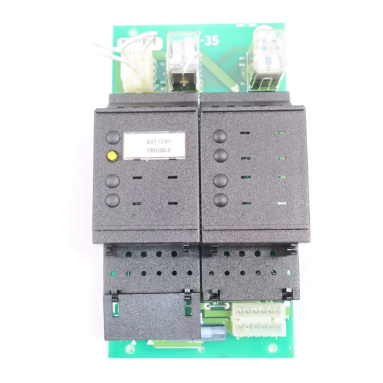
The Model BC-35 battery charger/transfer module complies
with UL Standard 864. The module is designed to monitor
the battery charge status and alert appropriate personnel
when the batteries may not have the standby power
capacity required by NFPA Standard 72 Local, Municipal Tie,
Remote Station, or Proprietary.
The BC-35 charging circuit provides a charging current
only if the voltage of the batteries being used is
between 18.3 VDC and 27.7 VDC. If the battery voltage is
out of this range, the BC-35 will automatically cut off its
charging circuit.
CAUTION: Disconnect the system power input before
installing the BC-35 and/or BE-35 cable connections.
The BC-35 module has a trouble signal for both high and
low battery conditions. A trouble condition occurs:
During normal AC operation when the instantaneous
or constant voltage across the battery is more than
30 volts peak or is less than 24 volts.
During the battery backup operation when the
instantaneous or constant voltage across the battery
is more than 30 volts peak or is less than 21 volts.
Siemens Industry, Inc.
Building Technologies Division
Florham Park, NJ
P/N 315-086767-5
MODEL BC-35
Siemens Building Technologies, Ltd.
Fire Safety & Security Products
2 Kenview Boulevard
Brampton, Ontario
L6T 5E4 Canada
Advertisement
Table of Contents

Related Manuals for Siemens BC-35


Summary of Contents for Siemens BC-35
- Page 1 18.3 VDC and 27.7 VDC. If the battery voltage is out of this range, the BC-35 will automatically cut off its charging circuit. CAUTION: Disconnect the system power input before installing the BC-35 and/or BE-35 cable connections.
- Page 2 A voltage check of the batteries should be performed to ensure that the BC-35 charging cir- cuit will begin charging. Follow Steps 1 and 2 below. Step 2 may also be used to troubleshoot the BC-35 when a trouble condition is indicated. Step 1 Test the batteries connected to the BC-35 module.
- Page 3 Step 2 Verify that the BC-35 is providing a charging current. a. If an MM-35 is being used in conjunction with a BC-35, check the meter and verify that a current is being supplied to the batteries either in a constant or a pulsed mode.
- Page 4 If the BC-35 is not providing a charging current, test pin 1 of the P1 plug on the BC-35 module in reference to the negative side of the power supply. If there are no volts at this point, replace the BC-35 module. If there are more than 2 VDC at this point, and no alarm is present, replace the CP-35 panel.
Need help?
Do you have a question about the BC-35 and is the answer not in the manual?
Questions and answers