Advertisement
Available languages
Available languages
Quick Links
English
Dear Customer,
Congratulations on the purchase of the EMP-Centauri Profi-line product. Before it's installation and
putting into operation, read carefully the entire operation manual. Keep the operation manual in a safe
place. The product may only be installed and connected with strict observance of the manual and of
valid regulations.
The area of application, warranty
The product is designed for distributing satellite, terrestrial TV and radio signals in normal house
installations. The warranty shall not apply, if the product is used for other than specified purpose. The
user will be responsible for injury or material damage which may arise in consequence of any use of
the product in contradiction with the manual. The product utilizes technologies which are protected by
copyrights and patents. It is prohibited and unlawful to dismantle the product and make any
interventions in it.
EMP-Centauri Profi-line products are covered under warranty for up to 4 (four) years from the date of
manufacturing. To enable superior warranty and post service warranty service, keep all purchase
records in a safe place. It is also recommended to keep the original packaging for the warranty period.
Technical specifications
Frequency range: 950-2300 MHz (satellite); 5-862 MHz (terrestrial)
Insertion loss: 5 dB avg (8 dB max)
Input isolation: 25 dB min
Power consumption (without connected LNB): 40 mA (18V)
Explanation of symbols on the product
DiSEqC (Digital Satellite Equipment control) – international standard for digital
Certificate of conformity
satellite equipment control, number (1.0, 1.1, 1.2 or 2.0) determines DiSEqC version.
Product installation & Configuration
Products must be installed and used on a dry place. To connect inputs and outputs, use quality coaxial
cable 75Ω with F connectors, which are designed for satellite reception. It is not allowed to break
coaxial cables, minimal bend radius is 5 cm. Tighten the F connectors with adequate power. Examples
of practicable connections are shown in this manual or at www.emp-centauri.cz.
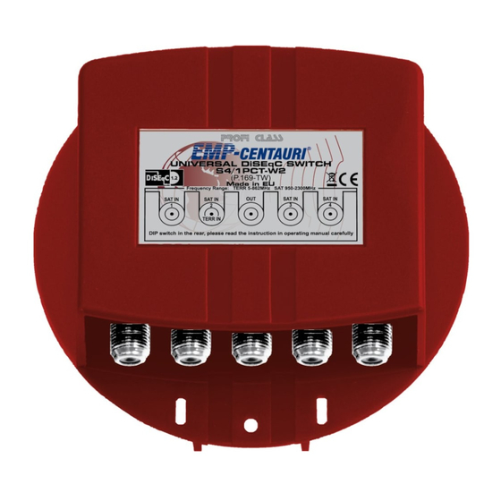
The switch P.169-TW contains 4 input ports for connecting input devices (LNB or multiswitches).
Output port shall be connected to user wall socket or directly to satellite receiver. The switch provides
terrestrial signal loop from input 2 to output.
During installation it is also necessary to set up required mode of operation by means of "dip-switch",
which is located on the rear side of the product (must be removed from plastic cover). Brief overview of
settings is given in Tab 1, more detailed info is provided later in description of particular modes.
Note: Change of any setting will not take affect until device is disconnected from power.
DIP-SWITCH
Description
1
Mode setting - higher bit (MSB)
2
Mode setting - lower bit (LSB)
3
Short / long response to analogue commands
4
DiSEqC messages transmission with / without repeat
Tab 1 Meaning of individual switching levers
Features, service modes
The product P.169-TW is universal configurable DiSEqC switch, capable to meet the highest
expectations for satellite distribution systems. According to chosen operation mode it can behave e.g.
like an ordinary four-way DiSEqC switch or like less common "uncommitted" DiSEqC 1.1 switch. While
these modes are typically used in applications where LNBs are to be switched, in modes 3 & 4 the
product can switch and control other connected distribution devices, e.g. satellite multiswitches. In
doing so, it operates as transcoder of "motor" commands (DiSEqC 1.2) to "multiswitch" messages
(DiSEqC 1.0), allowing to build a multi-user distribution system for up to 16 satellite positions. To
summarize, the switch accepts commands of levels DiSEqC 1.0, 1.1 & 1.2 from the master (satellite
receiver), selects one of it's inputs and generates appropriate analogue and DiSEqC 1.0 commands to
the slaves (LNBs, multiswitches), see Tab 2.
Mode
Commands generated by the switch
1
Polarization, Band + Toneburst + 0/22 kHz
2
Mode setting - lower bit (LSB)
3
Short / long response to analogue commands
4
DiSEqC messages transmission with / without repeat
Tab 2 Generated commands according to selected mode
Universal switch P.169-TW can be used only with DiSEqC - compatible satellite receivers. Availability
of particular operating mode depends on level of DiSEqC support implementation in given model of
satellite receiver. Please consult section "technical specifications" within user's manual of Your receiver
for information about supported DiSEqC features.
Note: For more convenient set up of whole system it is recommended to apply a DiSEqC monitor to
input ports of the switch (not included).
Description of operating modes
Mode 1 (SW 1 off & SW 2 off), see Fig "Mode 1"
Mode 1 requires satellite receiver with support of DiSEqC 1.0 (or higher). In this mode the product
operates as standard 4in/1out DiSEqC switch, choosing the input according to basic commands of
level DiSEqC 1.0 ("Position" and "Option"). Commands for polarization & band selection (analogue and
Mode 1
www.emp-centauri.cz
Example
E0 00 38 F0 – F3
E0 00 38 F0 – FF
E0 00 38 F0 – F7
E0 00 38 F0 – FF
P.169-TW
DiSEqC) are retransmitted to the desired input. Up to 4 LNBs (single, twin, quad, octo) can be
connected to input ports of the switch. Instead of any LNB, output of one-satellite (4 polarities)
multiswitches can be connected and switched as well. Terrestrial band can be distributed via input "2"
of the switch.
In this mode it is recommended to keep SW 3 in "off" and SW 4 in "on" position. If connecting a cas-
cade of DiSEqC devices to input port of the switch, it is necessary to allow DiSEqC commands
repeated transmission by setting SW 4 to "off" position. In installation menu of the receiver shall be
individual inputs of the switch addressed simply as "DiSEqC A", "DiSEqC B", "DiSEqC C" and "DiSEqC D".
Mode 2 (SW 1 off & SW 2 on), see Fig "Mode 2"
Mode 2 requires DiSEqC 1.1 compatible satellite receiver. In this mode the product operates as
extending "uncommitted" 4in/1out DiSEqC switch, controlled by DiSEqC 1.1 commands. The DiSEqC
1.0 commands ("Position", "Option", "Band" & "Polarization") and their analogue equivalents are
retransmitted to the desired input. The product can switch LNBs (single, twin, quad, octo), 2-way and
4-way DiSEqC 1.0 switches or various multiswitches. Terrestrial band can be distributed via input "2" of
the switch.
In this mode it is recommended to keep SW 3 in "off" and SW 4 in "on" position. If connecting a cas-
cade of DiSEqC devices to input port of the switch, it is necessary to allow DiSEqC commands
repeated transmission by setting SW 4 to "off" position. In installation menu of the receiver, individual
inputs of the switch shall be addressed simply as "uncommitted 1", "uncommitted 2", "uncommitted 3"
and "uncommitted 4".
If only LNBs and/or analogue-controlled multiswitches are switched, this setting should be sufficient. In
case of switching other DiSEqC controlled components (switches & multiswitches), their setting shall
be carried out just like they are connected directly to the receiver.
Mode 3 (SW 1 on & SW 2 off), see Fig "Mode 3"
In this mode the device emulates a DiSEqC motor, therefore DiSEqC 1.2 compatible satellite receiver
is required. According to accepted DiSEqC 1.2 commands the switch selects one of the inputs and
generates DiSEqC 1.0 level commands, which are transmitted to connected devices, see Tab 3.
Motor position
Selected input of
Transmitted
the switch
command
1
1
Position A
2
1
Position B
3
2
Position A
4
2
Position B
Tab 3: Function of the switch in mode 3
The product can switch LNBs (single, twin, quad, octo), 2-way DiSEqC 1.0 switches or multiswitches
with 8 input polarities. If other distribution devices are used (4-way DiSEqC switches, multiswitches for
more than two satellites), the product must be operated in mode 4. Terrestrial band can be distributed
via input "2" of the switch.
If connecting a cascade of DiSEqC devices to input port of the switch, it is necessary to allow DiSEqC
commands repeated transmission by setting SW 4 to "off" position, otherwise "on" position is sufficient.
Furthermore, SW 3 is recommended to be kept in "off" position. Satellite receiver shall be configured in
DiSEqC 1.2 mode: for each installed LNB do rotate west or east until desired signal will appear; then
immediately stop rotation and save the position. If this procedure fails, set SW 3 to "on", reset the
switch and try again.
Note: for successful LNB search we recommend to use low band transponders (up to 11700 MHz).
Mode 4 (SW 1 on & SW 2 on), see Fig "Mode 4"
In this mode the device emulates a DiSEqC motor, therefore DiSEqC 1.2 compatible satellite receiver
is required. According to accepted DiSEqC 1.2 commands the switch selects one of the inputs and
generates DiSEqC 1.0 level commands, which are transmitted to connected devices, see Tab 4.
Motor position
Selected input
Transmitted command Motor position
of the switch
1
1
Position A / Option A
2
1
Position B / Option A
3
1
Position C / Option A
4
1
Position D / Option A
5
2
Position A / Option B
6
2
Position B / Option B
7
2
Position C / Option B
8
2
Position D / Option B
Tab 4: Function of the switch in mode 4
This mode is required and best used whenever 4-way DiSEqC switches and/or multiswitches for
4 satellites are to be switched, but various types of LNB (single, twin, quad, octo) can be switched as
well. Terrestrial band can be again distributed via input "2" of the switch.
If connecting a cascade of DiSEqC devices to input port of the switch, it is necessary to allow DiSEqC
commands repeated transmission by setting SW 4 to "off" position, otherwise "on" position is sufficient.
Furthermore, SW 3 is recommended to be kept in "off" position. Satellite receiver shall be configured in
DiSEqC 1.2 mode: for each installed LNB do rotate west or east until desired signal will appear; then
immediately stop rotation and save the position. If this procedure fails, set SW 3 to "on", reset the
switch and try again.
Note: for successful LNB search we recommend to use low band transponders (up to 11700 MHz).
Device disposal
According to EU directive, electric and electronic devices which are identified by one of the following
symbols must not be disposed of together with municipal waste.
When disposing of the old device, use local waste collection and separation systems.
Motor position
Selected input of
Transmitted
the switch
command
5
3
Position A
6
3
Position B
7
4
Position A
8
4
Position B
Selected input
Transmitted command
of the switch
9
3
Position A / Option A
10
3
Position B / Option A
11
3
Position C / Option A
12
3
Position D / Option A
13
4
Position A / Option B
14
4
Position B / Option B
15
4
Position C / Option B
16
4
Position D / Option B
Advertisement

Subscribe to Our Youtube Channel
Related Manuals for EMP-Centauri P.169-TW


Summary of Contents for EMP-Centauri P.169-TW
- Page 1 EMP-Centauri Profi-line products are covered under warranty for up to 4 (four) years from the date of In this mode it is recommended to keep SW 3 in “off” and SW 4 in “on” position. If connecting a cas- manufacturing.
- Page 2 Vám za zakoupení výrobku profi řady EMP-Centauri. Před instalací a uvedením výrobku do V tomto módu se doporučuje ponechat SW 3 v poloze „off“ a SW 4 v poloze „on“. V případě, kdy je na provozu si pečlivě...
Need help?
Do you have a question about the P.169-TW and is the answer not in the manual?
Questions and answers