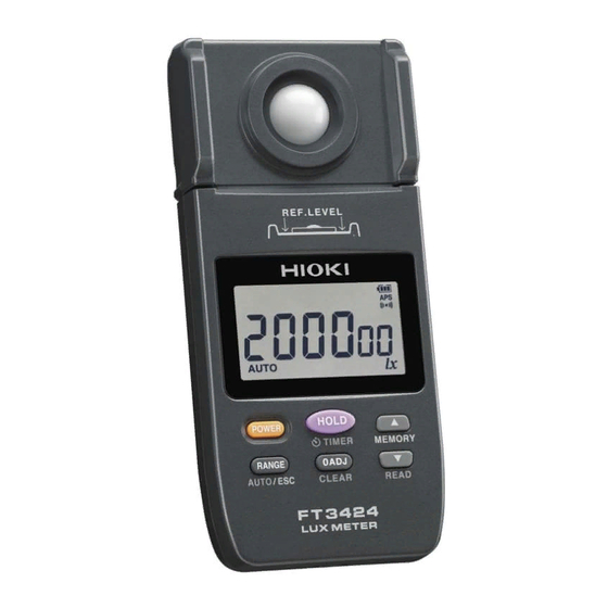
Hioki FT3424 Instruction Manual
Lux meter
Hide thumbs
Also See for FT3424:
- Instruction manual (166 pages) ,
- Instruction manual (83 pages) ,
- Instruction manual (132 pages)

Related Manuals for Hioki FT3424


Summary of Contents for Hioki FT3424
- Page 1 FT3424 FT3425 取扱説明書 照度計 Instruction Manual LUX METER 動画はこちらから▶ スキャンすると使い方の動画を見ることができます。 *通信料金はお客様のご負担となります。 JA/EN June 2019 Revised edition 6 FT3424A980-06 19-06H HIOKI FT3424A980-06...
- Page 2 HIOKI FT3424A980-06...
- Page 3 ............26 測定する ............... 27 測定レンジを選択する ........... 30 オートレンジで測定する ............ 30 マニュアルレンジで測定する ..........30 応用機能 設定時間後に測定値をホールドする (タイマホールド機能) ........... 31 測定値をホールドする ( ) TIMER ........31 表示部と受光部を離して使う ........32 索 受光部に三脚または一脚を取り付ける ..... 33 引 測定補助カートを使う 3.4 Z5023 ........ 34 HIOKI FT3424A980-06 FT3424A980-06...
-
Page 4: Table Of Contents
確度 ................. 54 特性 ................. 54 出力仕様 ............... 55 機能仕様 ............... 56 一般仕様 ............... 56 通信仕様 ( のみ) 4.6 Bluetooth FT3425 ....... 58 付 保守・サービス 録 修理・点検・クリーニング ........59 困ったときは ............61 エラー表示 ............63 メッセージ一覧 ............. 64 HIOKI FT3424A980-06... - Page 5 付録 付 付録 法定照度計について ........付 付録 照度基準例 (参考) ........... 付 付録 センサ特性グラフ ........... 付 可視域相対分光応答度特性 付 ..........斜入射光特性 付 ..............付録 その他の特性 付 ..........付録 寸法図 付 ............保証書 .................. 保 付 録 索 引 HIOKI FT3424A980-06...
- Page 6 HIOKI FT3424A980-06...
- Page 7 はじめに はじめに このたびは、 照度計 をご選定いただき、 HIOKI FT3424 FT3425 誠にありがとうございます。この製品を十分にご活用いただき、末 長くご使用いただくためにも、取扱説明書はていねいに扱い、いつ もお手元に置いてご使用ください。 は 通信機能を備えており、スマートフォンや ® FT3425 Bluetooth タブレットで測定データをモニタおよび記録できます。 を以降 「本器」 または 「本体」 と記載します。 FT3424 FT3425 商標について は の登録商標です。日置電機株 Bluetooth ® Bluetooth SIG Inc. • 式会社はライセンスに基づき使用しています。 、 は の商標です。 Android Google Play Google Inc.
- Page 8 梱包内容の確認 梱包内容の確認 本器がお手元に届きましたら、輸送中において異常または破損がな いか点検してからご使用ください。 特に付属品および、パネル面の操作キー、端子類に注意してくださ い。万一、 破損あるいは仕様どおり動作しない場合は、 お買上店 (代 理店) か最寄りの営業拠点にご連絡ください。 梱包内容が正しいか確認してください。 FT3424 または 単 形アルカリ乾電池 ( ) 本 FT3425 携帯用ケース ストラップ (本体用) (ソフトケース) ( p. 24 ) センサキャップ (ストラップ付) ( p. 27 ) 取扱説明書 ( ド ラ イ バ、...
-
Page 9: L9820
オプション (別売) について 本器には次のオプションがあります。お買い求めの際は、お買上店 (代理店) か最寄りの営業拠点にご連絡ください。 オプションは、変更になる場合があります。弊社ウェブサイトで最 新の情報をご確認ください。 接続ケーブル 受光部と表示部を分離して使用するときの接続ケーブルです。 L9820 接続ケーブル (長さ ) 出力コード 出力機能を使用するときに必要です。 出力コード 出力コード L9094 L9095 (長さ 、バナナ端子用) (長さ 、 端子用) 1.5 m 1.5 m 付 L9096 出力コード 録 (長さ 、端子台用) 1.5 m 索 引 HIOKI FT3424A980-06... - Page 10 オプション (別売) について 携帯用ケース 接続ケーブルや、 出力コード、 ケーブル L9820 L9094/L9095/L9096 を一緒に収納するのに便利な携帯用ケースです。 C0202 携帯用ケース C0201 携帯用ケース (ソフトケース) (セミハードケース) 接続ケーブル L9820 は収納できません。 測定補助具 本器を取り付けることで、床面の照度を立ったまま測定できる便利なカート です。測定箇所を簡単に移動できます。また、一脚を取り付けて、床面から の高さを固定できます。 測定補助カート Z5023 HIOKI FT3424A980-06...
- Page 11 状態で出荷されています。ただし、この取扱説明書の記載事項を守 らない場合は、本器が備えている安全確保のための機能が損なわれ る可能性があります。 本器を使用する前に、 次の安全に関する事項をよくお読みください。 注 意 • 誤った使いかたをすると、機器の故障につながる可能 性があります。この取扱説明書を熟読し、十分に内容 を理解してから操作してください。 • 電気計測器を初めてお使いになる方は、電気計測の経 験がある方の監督のもとで使用してください。 表記について 本書では、リスクの重大性および危険性のレベルを以下のように区 分して表記します。 作業者が死亡または重傷を負う可能性のある場合につい 警 告 て記述しています。 作業者が軽傷を負う可能性のある場合、または機器など 注 意 に損害や故障を引き起こすことが予想される場合につい て記述しています。 操作および保守作業上、特に知っておかなければならな 重要 い情報や内容がある場合に記述します。 してはいけない行為を示します。 付 録 必ず行っていただく 「強制」 事項を示します。 索 説明を下部に記載しています。 引 HIOKI FT3424A980-06...
-
Page 12: Hioki Ft3424A980
注意や危険を示します。機器上にこの記号が表示されている 場合は、取扱説明書の該当箇所を参照ください。 直流 ( ) を示します。 無線技術を搭載していることを示します。 Bluetooth ® 規格に関する記号 加 盟 国 に お け る、 電 子 電 気 機 器 の 廃 棄 に 関 わ る 法 規 制 ( 指令) のマークです。 WEEE 指令が示す規制に適合していることを示します。 HIOKI FT3424A980-06... - Page 13 ただし、一部上記と異なる表示があります。 電源遮断時に表示 ( ) p. 19 表示部と受光部が接続されていないときに表示 確度について 弊社では測定値の限界誤差を、次に示す ( フルスケール) 、 f.s. rdg. (リーディング) 、 ( ディジット) に対する値として定義してい dgt. ます。 (最大表示値) 最大表示値を表します。一般的には、現在使用中のレンジを表 f.s. します。 付 (読み値) rdg. 録 現在測定中の値、測定器が現在表示している値を表します。 (分解能) dgt. 最小表示単位、最小桁の “ ” を表します。 索 引 HIOKI FT3424A980-06...
- Page 14 ご使用にあたっての注意 • 本器を安全にご使用いただくために、また機能を十二分にご活用 いただくために、次の注意事項をお守りください。 • 本器の仕様だけではなく、使用する付属品、オプション、電池な どの仕様の範囲内で本器をご使用ください。 ご使用前の確認 保存や輸送による故障がないか、点検と動作確認をしてから使用し てください。故障を確認した場合は、お買上店 (代理店) か最寄り の営業拠点にご連絡ください。 本器の設置について 使用温湿度範囲については仕様 ( ) をご覧ください。 p. 56 警 告 本器の故障、事故の原因になりますので、次のような場 所には設置しないでください。 • 高温になる場所 • 腐食性ガスや爆発性ガスが発生する場所 • 水、油、薬品、溶剤などがかかる場所 • 多湿、結露する場所 • ほこりが多い場所 • 機械的振動が多く発生する場所 光学部品は熱に弱いため、本器を使用しないときは、冷暗所で保 管してください。 HIOKI FT3424A980-06...
- Page 15 • ケーブル、コード類の被覆が破れたり、金属が露出し たりしていないか、使用する前に確認してください。 損傷がある場合は、正しい測定・通信ができませんの で、弊社指定のものと交換してください。 • ケーブル、コード類の被覆に損傷を与えないため、踏 んだり挟んだりしないでください。 • 断線による故障を防ぐため、コネクタやジャックの付 け根を折ったり、引っ張ったりしないでください。 ℃以下の環境では、ケーブル、コード類が硬くなりま • す。この状態でケーブル、 コード類を曲げたり、 引っ張っ たりした場合、ケーブル、コード類の被覆破損および 断線の可能性がありますので注意してください。 本器の取り扱い 注 意 • 本器は受光部と表示部が分離できる構造になっていま す。本器の故障を避けるため、必ず電源を切ってから 受光部と表示部を分離または接続してください。 • 本器の損傷を防ぐため、運搬および取り扱いの際は振 動、衝撃を避けてください。特に、落下などによる衝 撃に注意してください。 付 録 • 本器の損傷を避けるため、 端子を短絡し D/A OUTPUT たり、電圧を入力したりしないでください。 索 引 HIOKI FT3424A980-06...
- Page 16 • 受光部と表示部を分離して使用するときは、必ず弊社指定の 接続ケーブルを使用してください。 指定以外の接続ケー L9820 ブルを使用すると接触不良などで正確に測定できない場合があ ります。 • 一般の照明器具の下での照度測定において、表示が安定しない ことがあります。これは照明器具の電源電圧の変動、周囲の環 境 (人の影など) によるものがほとんどです。これらの点に注 意して測定してください。 • 低照度下で測定するときのために、 表示部にバックライ トを備えています。測定値をホールドした状態、または、内部 メモリに保存した測定値データを読み出した状態で、低照度環 境 (約 以下) のときだけ、バックライトが自動で点灯し ます。バックライトが測定に影響しないよう、測定中にバック ライトを点灯させることはできません。 • 本器の測定基準面 ( ) は、 下図の色付きの部分です。 REF.LEVEL 測定基準面 ( ) REF.LEVEL • 本器を分解したり、衝撃を加えたりしないでください。 HIOKI FT3424A980-06...
- Page 17 ご使用にあたっての注意 ご使用にあたっての注意 • ディスクの記録面に汚れや傷がつかないようご注意ください。 また、文字などをレーベル面に記入するときは、先の柔らかい 筆記用具をお使いください。 • ディスクは保護ケースに入れ、直射日光や高温多湿の環境にさ らさないでください。 • このディスクのご使用にあたってのコンピュータシステム上の トラブルについて、弊社は一切の責任を負いません。 輸送時の注意 本器を輸送する際は、以下のことにご注意ください。 なお、 輸送中の破損については保証しかねますのでご了承ください。 注 意 • 振動や衝撃で破損しないように取り扱ってください。 • 本器の損傷を避けるため、付属品やオプション類を本 器から外してください。 長時間使用しない場合 重要 電池の液漏れによる腐食と本器の損傷を防ぐため、長い間使用し ないときは、電池を抜いて冷暗所で保管してください。 付 録 索 引 HIOKI FT3424A980-06...
- Page 18 ご使用にあたっての注意 HIOKI FT3424A980-06...
- Page 19 と、自動でバック ライトが点灯 測定値をメモリ 本体内部メモリに最大 個 の測定値データを保存可能 に一括データ送信可能 付 録 Bluetooth 通信 ( FT3425 のみ) 測定値ホールド スマートフォンやタブレットで測 タイマホールド機能を搭載 定データをモニタと記録 索 専 用 ス マ ー ト フ ォ ン ア プ リ ケ ー 引 を使用 ション GENNECT Cross HIOKI FT3424A980-06...
- Page 20 端子 表示マーク (ミニ タイプ) 表示部 表 ( p. 18 ) 示 部 D/A OUTPUT 端子 ( p. 41 ) 操作キー部 ( ) p. 15 ストラップ穴 ( p. 24 ) 受光部と表示部の つに分かれていて、分離できます。 ( ) p. 32 (オプションの 接続ケーブルを使用) L9820 HIOKI FT3424A980-06...
- Page 21 各部の名称と機能 操作キー FT3424 FT3425 押しながら 通常 秒以上長押し 電源を入れる 電源を入れる 電源を切る ー 測定値をホール タイマホールド機能を起動 オートパワーオ ドまたはホール ( ) フ機能 ( ) の p. 31 ドを解除 〜 秒後 (時間指定可 解除 ( ) p. 37 能) に自動でホールド 付 録 索 引 HIOKI FT3424A980-06...
- Page 22 定 値 デ ー タ を 読 み 出 し に設定 ( ) p. 50 • タイマ残時間 ( ) p. 39 を減少 • メ モ リ を 連 続 で 減少 ( ) p. 39 と同時に長押し • すると、 通 Bluetooth 信機能を起動 解除 (設定は本体で記録) 内部メモリに保存した測定値データの読み出しモード時 内部メモリに測定値データが複数保存されているときだけ、 を操作できます。 タイマホールド機能動作中 HIOKI FT3424A980-06...
- Page 23 各部の名称と機能 背面 検定証印 本器が検定済みの場合、有効期限を示 すラベルが貼られています。 ( 付 ) 取付ネジ穴 受光部を三脚、一脚、または 測 Z5023 定補助カートに取り付ける場合に使用 します。正面の照度センサ中心位置の 真裏に位置します。 ( ) p. 33 合番号 受光部と表示部の合番号が同一である ことを確認して使用してください。 製造番号 製品保証など、管理上必要ですので、 はがさないでください。 測定レンジ 本器の測定レンジを表記しています。 電池カバー 電池交換時にカバーを取り外します。 使用する電池の説明を記載しています。 参照 p. 22 付 録 索 引 HIOKI FT3424A980-06...
- Page 24 (測定値データの読み出し、タイマ残時間の設定) 電池残量 ( ) p. 19 オートパワーオフ機能有効 ( ) p. 37 ブザー音有効 ( ) p. 50 測定値が設定レンジの最大照度範囲を超えている状態 オートレンジ有効 ( ) p. 30 出力機能有効 ( ) p. 41 照度の単位記号 (ルクス) 通信機能有効 ( のみ) Bluetooth FT3425 ( ) p. 45 HIOKI FT3424A980-06...
- Page 25 ると電源遮断する場合があります。 ( ) p. 22 消灯 通信時および バスパワー接続時は、電池残量表示が消 灯します。 電池残量表示は連続使用時間に対するおおよその目安です。 マンガン乾電池やニッケル水素電池を使用している場合は、電池残量表示が 正しく動作しません。 電源遮断 付 電 池 残 量 が な く な る と、 表 示 部 に 録 [ ] が 秒間点滅し、自動で電源が切 b. Lo れます。 索 引 HIOKI FT3424A980-06...
- Page 26 表示について HIOKI FT3424A980-06...
- Page 27 8 設置・接続 センサキャップを装着したまま電池を入れる ( p. 22 ) 必要に応じて、その 他オプション類の準 備をします。 使用前の点検をする ( p. 26 ) 測定 電源を入れてゼロアジャストを実行する (必要に応じて) Bluetooth 通信機能を有効にして、スマートフォ ンと通信を開始する ( FT3425 のみ) センサキャップを外して測定を開始する (必要に応じて) 測定値をホールドする 付 測定値を内部メモリに保存する ( ) p. 38 録 終了 索 引 電源を切ってセンサキャップを装着する HIOKI FT3424A980-06...
- Page 28 電池を取り付ける・交換する 本器を最初に使用するときは、単 形アルカリ乾電池 ( ) 本を 取り付けてください。また、測定前には十分な電池残量があるか確 認してください。残量が少ない場合は、電池を交換してください。 ニッケル水素電池の使用について 使用できますが、アルカリ乾電池とは放電特性が異なるため、電池 残量表示が正しく動作しません。ご注意ください。 警 告 • 電池をショート、充電、分解または火中への投入はしな いでください。破裂するおそれがあり危険です。 • 感電事故を避けるため、出力コード、 ケーブルを 外してから、電池を交換してください。 • 交換後は、必ず電池カバーを取り付けてから使用して ください。 注 意 性能劣化や電池の液漏れの原因になりますので、以下を お守りください。 • 新しい電池や古い電池、種類の違う電池を混在して使 用しないでください。 • 極性+ーに注意し、逆向きに入れないでください。 • 使用推奨期限を過ぎた電池は使用しないでください。 • 使い切った電池を本器に入れたままにしないでください。 電池の液漏れによる腐食と本器の損傷を防ぐため、長い 間使用しないときは、電池を抜いて保管してください。 HIOKI FT3424A980-06...
- Page 29 • 電池を交換する前に、電源を切ってください。 • 使用後は必ず電源を切ってください。 電池は地域で定められた規則に従って処分してください。 • 以下のものを用意する • 単 形アルカリ乾電池 ( ) 本 を長押しして電源を切る 本器の電源を切る 背面 電池カバーをスライドし て外す 電池を交換する場合は、 4, 5 古い電池をすべて取り出 す 新しい単 形アルカリ乾 電池 本を極性に注意し て入れる 付 録 電池カバーを取り付ける 単 形マンガン乾電池 ( ) も使用できますが、連続使用時間が 索 アルカリ乾電池に比べ短くなります。 引 HIOKI FT3424A980-06...
- Page 30 ストラップを取り付ける ストラップを取り付ける 表示部の底面にあるストラップ穴に、付属のストラップ (本体用) とセンサキャップのストラップを取り付けることができます。 注 意 ストラップは本器の取り付け部に確実に取り付けてくださ い。取り付けが不十分だと、持ち運びの際に本器が落下し、 破損するおそれがあります。 ストラップを つ取り付ける場合 HIOKI FT3424A980-06...
- Page 31 ストラップを取り付ける ストラップを つ取り付ける場合 ストラップ (本体用) センサキャップのストラップ 付 録 索 引 HIOKI FT3424A980-06...
- Page 32 故障を確認した場合は、お買上店 (代理店) か最寄りの営業拠点に ご連絡ください。 本器外観の確認 点検項目 対処 • 本器に破損しているところや 目視で確認してください。 亀裂がない 損傷がある場合は、正しく測定できませ • 内部回路が露出していない んので、使用しないで修理に出してくだ さい。 電源投入時の確認 点検項目 対処 電池残量は十分にある 表示部右上の電池残量表示が の 場合は、すぐに新しい電池と交換してくだ さい。使い続けると電源遮断する場合があ ります。 ( ) p. 22 表示項目に欠けているところ 全点灯表示で確認してください。 、 ) はない ( p. 16 p. 18 欠けている場合は修理に出してください。 HIOKI FT3424A980-06...
- Page 33 測定する 測定する センサキャップを装着 付属のセンサキャップを照度セン サ部に装着した状態で、電源を入 れる 表示部に数字が表示されます。 を押して電源を入れる を押す が表示され、すべてのレンジの [ ] ゼロアジャストが実行されます。 ゼロアジャストが完了すると が [ ] 消えます。 センサキャップを外し、測定する 位置に受光部を近づける 付 録 索 引 HIOKI FT3424A980-06...
- Page 34 測定する (特定のレンジに固定して測定したいときは) を押してレンジを選択する 参照: 「 測定レンジを選択する」 ( ) p. 30 測定値が安定したら測定値を読み 取る (測定値をホールドしたいときは) を押し、測定値を読み取る 再度 を押すと、測定値のホー ルドが解除されます。 設定した時間経過後に測定値をホールド することもできます。 参照: 「 設定時間後に測定値をホールドする (タイマホールド機能) 」 ( ) p. 31 センサキャップを装着 測定が終了したら、センサキャッ プを装着して電源を切る を長押しして電源を切る HIOKI FT3424A980-06...
- Page 35 付属のセンサキャップを照度センサ部に正 しく装着していない ( 相当以上のカウ ントがある) 場合に を押すと、 表示部に が表示されます。 [ ] セ ン サ キ ャ ッ プ を 正 し く 装 着 し て か ら、 再度 を押してください。 表示中に を長押しすると、ゼロアジャストモードが [CAP] 解除されます。 付 録 索 引 HIOKI FT3424A980-06...
- Page 36 (出力機能 ( ) 使用時は無効) OUTPUT • マニュアルレンジ 特定のレンジに固定設定 オートレンジで測定する 電源を入れると、オートレンジで測定が始ま ります。 点灯 (初期設定) マニュアルレンジで測定する を押す レンジからマニュアルレンジに切り替 AUTO わり、オートレンジで選択されていたレンジ に固定されます。 ( 消灯) を押すたびに、 レンジが切り替わります。 → → 200000 20.00 200.0 ↑ ↓ ← 20000 2000 オートレンジに切り替えたいとき を長押しする ( 点灯) 測定値をホールドした状態では、 レンジの切り替えができません。 HIOKI FT3424A980-06...
-
Page 37: Timer
下になると、 秒ごとにブザーが鳴ります。 タイマホールド機能動作中に または で、タイマ残時間を変更できます。 ( 秒から選択) 初期設定: 秒 設定した時間が経過した後に、測定値がホー ルドされます。 ( および 点灯、 秒間連続でブザー音) 再度 を押すと、測定値のホールド が解除され、タイマホールド機能は無効にな ります。 ( および 消灯) 付 録 • タイマホールド機能動作中 (カウントダウン中) に を押 すと、測定値をホールドします。このときタイマホールド機能 索 は無効になります。 ( 消灯) 引 • 測定値をホールドした状態では、 レンジの切り替えができません。 HIOKI FT3424A980-06... - Page 38 表示部と受光部を離して使う 表示部と受光部を離して使う 表示部と受光部を分離して測定できます。 本器の電源を切る 表示部と受光部を押さえ、左右にゆっくり引き離す L9820 接続ケーブル (オプション) で、表示部と受光部を 接続する 電源が入った状態で、表示部と受光部を分離したり、接続したり しないでください。 HIOKI FT3424A980-06...
- Page 39 受光部に三脚または一脚を取り付ける 受光部に三脚または一脚を取り付ける 設置 (床面からの高さを固定) して測定するときは、市販の三脚ま たは一脚を本器に取り付けて使用します。 受光部背面の取付ネジ穴 に三脚または一脚を取り付けてくださ い。 ネジサイズ: インチネジ ( に準拠) JIS B7103 例:本器を三脚に取り付けた場合 付 • 三脚または一脚を取り付けるときは、本器を回さずにネジを回 録 してください。 • 三脚または一脚を取り付けた状態で、本器を持って運ばないで ください。 索 引 HIOKI FT3424A980-06...
- Page 40 測 定 補 助 カ ー ト に 取 り 付 け る と、 床 面 の 照 度 を Z5023 立ったまま測定できます。測定箇所を簡単に移動できます。また、 に一脚を取り付けて、床面からの高さを調整し固定できま Z5023 す。 注 意 は手持ち部の長さを調整できます。調整後はロッ Z5023 • クを締め、長さがしっかり固定されたことを確認してか ら使用してください。 の車輪に付着した、汚れや異物を取り除いてから Z5023 • 使用してください。汚れや異物の付着があると、床面を 汚したり傷つけたりするおそれがあります。 • 本器の受光部に、作業者の影がかからないように注意し て使用してください。影がかかった場合、測定値が低く なります。 • 本器を に取り付けた状態で、段差がある床面を Z5023 走行しないでください。 の手持ち部を折りたたむときに、手持ち部と台車 Z5023 • 部との間に指を挟まないでください。 HIOKI FT3424A980-06...
- Page 41 測定補助カートを使う Z5023 使い方 L9820 接続ケーブルを使用 スマートフォンを使用 ( FT3424 FT3425 ) ( FT3425 のみ) 表示部 L9820 手持ち部 本器 受光部 台車部 付 録 索 引 HIOKI FT3424A980-06...
- Page 42 本器 (受光部背面) と をネジ (付属) で固定します。 Z5023 ネジサイズ: インチネジ ( に準拠) JIS B7103 ネジ 本器 Z5023 参考:一脚 (市販品) の固定方法 本器 (受光部背面) と一脚、および一脚と を各々ネジ で固 Z5023 定します。 ネジサイズ: インチネジ ( に準拠) JIS B7103 本器 インチネジ 一脚 インチネジ ( 付属) Z5023 Z5023 HIOKI FT3424A980-06...
- Page 43 秒前になる とブザー断続音でお知らせします。電源を切らずに引き続き本器を 使用するときは、正面のいずれかのキーを押してください。キーを 押した時点から再び無操作の状態が約 分間続くと、自動で電源 が切れます。 • 長時間連続で使用するときは、あらかじめオートパワーオフ機 能を無効に設定してください。 • 使用後は必ず電源を切ってください。 • 出力機能 ( ) 使用時、 通信時、 バスパワー OUTPUT 接続時、および 通信時は、オートパワーオフ機能が Bluetooth 無効になります。 オートパワーオフ機能を無効にする 電源が入っている場合は、電源を切ってください。 を押しながら、 を押して 電源を入れる オートパワーオフ機能が無効になります。 付 表示部に が点灯していないことを 録 確認してください。 電源を切るまで、オートパワーオフ機能は無効になります。 索 電池消耗にご注意ください。 引 HIOKI FT3424A980-06...
-
Page 44: 測定値を保存する (メモリ機能
を、小さいメモリ から順番に内部メモリ に保存します。 こ の と き、 ブ ザ ー が 鳴 り、 メ モ リ と が 秒間点灯します。 内部メモリがいっぱいのとき 内部メモリがいっぱいのとき (保存 した測定値データが 個のとき) に 新たに測定値を保存しようとすると、 表示部に が表示されま [ ] FULL す。内部メモリに新たに測定値を保 存したいときは、保存した測定値デー タを消去してください。 ( ) p. 40 HIOKI FT3424A980-06... -
Page 45: Read
を連続で増減できます。 内部メモリに測定値データが複数保存さ れているときだけ、 を操作 できます。 低照度環境 (約 以下) で内部メモ リの測定値データを読み出すと、自動で バックライトが点灯します。 読み出しモードを解除したいとき ( ) を押す ( 消灯) 測定値データが保存されていないとき 内部メモリに測定値データが保存されていな いときに ( ) を押すと、 表 READ 付 示部に が約 秒間表示され、測定値 [ ] - - - 録 表示画面に戻ります。 索 引 HIOKI FT3424A980-06... -
Page 46: Clear
最後に保存した測定値データを消去する ( ) CLEAR メモリ ( ) を長押しする READ ( および 点灯) 内部メモリに保存した測定値データの 読み出しモードになります。 ( ) を長押しする CLEAR 最後に保存した測定値データ (最後のメ モリ ) だけが消去されます。 任意のメモリ の測定値データを消去することはできません。 保存したすべての測定値データを消去する 電源が入っている場合は、電源を切ってください。 を押しながら、 を押し て電源を入れる 表示中に を長押しする [CLr] 保存したすべての測定値データが消去さ れます。 点滅後、測定値表示画面 [CLr] になります。 HIOKI FT3424A980-06... -
Page 47: 照度をロギングする (出力機能
ます。 測定値の有効数字 カウントに対して の電圧出力機能で、 DC 1 mV 本器の 表示の更新レートに合わせて電圧が変化します。 注 意 断線防止のため、出力コードを引き抜くときは、差込部 分 (コード以外) を持って抜いてください。 • 出力機能 ( ) 使用時は、次の機能が無効になります。 OUTPUT オートパワーオフ機能 メモリ機能 オートレンジ • 出力機能を長時間使用するときは、 ケーブルを接続し、 バスパワーで電源を供給してください。 • 出力コードを差し込んだまま電源を入れると、 の信号 +2.5 V を一時的に出力しますが、異常ではありません。 付 録 索 引 HIOKI FT3424A980-06... - Page 48 出力レート DC 1 mV / 0.01 DC 1 mV / 0.1 各レンジのフルスケールを超 えたとき、出力は DC 2.5 V 2000 DC 1 mV / 1 になります。 ( 表示部に 点灯) 20000 DC 1 mV / 10 200000 DC 1 mV / 100 HIOKI FT3424A980-06...
- Page 49 ケ ー ブ ル を 使 用 し て、 に デ ー タ を 送 信 し た り、 本器を制御したりできます。 詳細は、付属 の通信仕様書をご覧ください。 専用 アプリケーションソフトウェアを にインストールする Bluetooth 通信機能が無効になっていることを確認する に本器を接続する インタフェースには、 の仮想 ポートを使用しています。 ケーブル データ送信 本器を制御 付 録 索 引 HIOKI FT3424A980-06...
- Page 50 と通信する ケーブルを接続する前に、 通信機能が無効に Bluetooth • なっていることを確認してください。 通信機能が有 Bluetooth 効のまま ケーブルを接続すると、 通信ができません。 ケーブルを接続した状態で、 通信機能を有効 Bluetooth • または無効にすることはできません。 ケーブルを接続するときは、コネクタの向きに注意して • ください。 通信中は 表示部に が点灯します。 • 通信中は、 ケーブルを外さないでください。外して • 通信が途絶えると、専用 アプリケーションソフトウェア側 で警告を表示します。 ケーブルを再接続してください。 HIOKI FT3424A980-06...
-
Page 51: Ft3425
GENNECT Cross をインストールする (p. 47) と を同時に長押しして、 の 通 FT3425 Bluetooth 信機能を有効にする GENNECT Cross を 起 動 し、 FT3425 を 接 続 登 録 す る (p. 48) 標準測定 または 照度測定 を選択して測定する (p. 49) 付 録 索 引 HIOKI FT3424A980-06... - Page 52 スマートフォンやタブレットと通信する ( のみ) FT3425 • 本器の電源を切っても、 通信機能の設定 (有効または Bluetooth 無効) を記憶しています。 通信機能が有効の場合は、本器の マークが点灯し Bluetooth • ます。 通信中は、本器の マークが点滅します。 Bluetooth • 通信機能を有効にしたままパソコンに 接続する Bluetooth • と、 通信より 通信動作が優先されます。 (本器の Bluetooth 電源は電池ではなく バスパワーで動作します) HIOKI FT3424A980-06...
- Page 53 アカウントが Google Play Google 必要です。各アカウントの取得方法については、各携帯端末購入先 にお問い合わせください。 は電波を発生するため、認可された国と地域以外で使 FT3425 • 用した場合は、法律違反により罰せられるおそれがあります。 詳細は、付属の 「電波使用上の注意」 または弊社ホームページ を参照してください。 は一部の国々での販売となります。詳細については、 FT3425 • お買上店 (代理店) か最寄りの営業拠点にお問い合わせくださ い。 通信可能距離は、障害物 (壁、金属の遮へい物など) Bluetooth • および床や地面との距離で大きく変わります。安定して測定を 行うために、電波強度が十分にあることを確認してください。 • このアプリケーションソフトは無料ですが、ダウンロードやア プリケーションご使用の際のインターネット接続費用について はお客様のご負担となります。 • このアプリケーションソフトは、すべての携帯端末での動作を 付 保証するものではありません。 録 索 引 HIOKI FT3424A980-06...
- Page 54 スマートフォンやタブレットと通信する ( のみ) FT3425 照度計 ( ) を接続登録する FT3425 • 初回起動時 (登録機器がない場合) は、接続設定画面で起動しま す。 • 接続設定画面では、 が近くにあると、自動的に接続登録 FT3425 されます (最大 台) 。 台の が同時に通信できる携帯端末は 台のみです。 FT3425 • が他の携帯端末と通信している場合は、接続機器登録で FT3425 きませんので、他の携帯端末との接続を解除してください。 • 本器の電源を入れてから登録されるまで 秒〜 秒程度お待ち ください。 分以上待っても登録されないときは、 GENNECT と本器を再起動してください。 Cross HIOKI FT3424A980-06...
-
Page 55: Bluetooth
スマートフォンやタブレットと通信する ( のみ) FT3425 機能を使用して測定する Bluetooth ホーム画面で、 または を選択し、測定して 標準測定 照度測定 ください。各機能の詳細は、 の使い方ガイドを GENNECT Cross 参照してください。 標準測定機能 照度測定機能 照度測定機能 (測定場所表示画面) (リスト表示画面) 付 録 索 引 HIOKI FT3424A980-06... - Page 56 ブザー音を無効にする ブザー音を無効にする 3.10 工場出荷時 (初期設定) は、ブザー音が有効になっています。 設定を変更するときは、電源を切ってください。 を押しながら、 を押して 電源を入れる が表示され、ブザー音が無効にな [bP oFF] ります。 を放すと測定値表示画面になります。 ( 消灯) 電源を切るまで、ブザー音は無効になります。 HIOKI FT3424A980-06...
-
Page 57: バックライトを点灯する
バックライトを点灯する バックライトを点灯する 3.11 低照度下で測定するときのために、 表示部にバックライトを 備えています。測定値をホールドした状態、または、内部メモリに 保存した測定値データを読み出した状態で、低照度環境 (約 以下) のときだけ、バックライトが自動で点灯します。 バックライトが測定に影響しないよう、測定中にバックライトを点 灯させることはできません。 バックライトを強制的に点灯させる 約 以上の照度環境でもバックライトを点灯させたいときは、 測定値をホールドした状態で、照度センサ部にセンサキャップを装 着してください。 バックライトの点灯または消灯は、ホールドしている測定値とは 関係ありません。照度センサが常時照度を監視していて、監視照 度約 を基準にバックライトの点灯または消灯を判断しま す。 付 録 索 引 HIOKI FT3424A980-06... - Page 58 バックライトを点灯する HIOKI FT3424A980-06...
- Page 59 仕様 基本仕様 • 階級 一般形 級 分類 JIS C 1609-1:2006 • 型式 計量法 型式承認第 ( ) E141 FT3424 型式承認第 ( ) E181 FT3424,FT3425 • 表示器 液晶表示 桁 表示 • 有効表示桁 カウント 2000 • 表示単位 (ルクス) • 表示更新レート 500 ms 20 ms 測定レンジ...
- Page 60 調整後確度保証期間 (最大表示値) 最大表示値を表します。 f.s. • 一般的には、現在使用中のレンジを表します。 (読み値) 現在測定中の値、測定器が現在表示している値を表し rdg. • ます。 (分解能) 最小表示単位、最小桁の “ ” を表します。 dgt. • 特性 系統的な外れ : 以下 斜入射光特性 余弦角からの外れ: 斜入射角度 余弦則からの外れ オートレンジ: 秒以下 応答時間 マニュアルレンジ: 秒以下 ℃ 〜 ℃における、 ℃時の測定値からのずれ: 温度特性 3% rdg. HIOKI FT3424A980-06...
- Page 61 DC 1 mV / 0.1 2000 DC 1 mV / 1 20000 DC 1 mV / 10 200000 DC 1 mV / 100 付 出力更新レート 500 ms 20 ms 録 (表示カウントに対して) 出力確度 1% rdg. 5 mV 以下 出力抵抗 1.1 kΩ 索 引 HIOKI FT3424A980-06...
-
Page 62: 一般仕様
保存した測定値データを読み出した状態で、周囲照 度が を下回った場合、バックライト点灯 ゼロ点調整 ゼロアジャスト ゼロアジャスト実行時間: 秒以下 一般仕様 年間 製品保証期間 シリコンフォトダイオード 受光素子 ( ) インタフェース USB 2.0 FT3424, FT3425 ( のみ) Bluetooth 4.0LE FT3425 〜 、 以下 (結露しないこと) 使用温湿度範囲 -10 C 40 C 80% rh 〜 、 以下 (結露しないこと) 保存温湿度範囲... - Page 63 単 形マンガン乾電池 ( ) 本 定格電源電圧 DC 1.5 V (最大許容電圧 ) DC 3.6 V バスパワー DC 5 V : 約 時間 連続使用時間 FT3424 : 約 時間 ( 通信なし) FT3425 Bluetooth 約 時間 ( 通信あり) Bluetooth (単 形アルカリ乾電池使用時) 最大定格電力 500 mVA 約...
-
Page 64: 通信仕様 ( Ft3425 のみ
1 mW 見通し約 通信距離 10 m ( ) 通信プロファイル GATT Generic Attribute Profile 対応 端末: 以上 接続先 iOS 10 ( 対応機種のみ) Bluetooth low energy 対応 端末: 以上 Android Android 4.3 ( 対応機種のみ) Bluetooth low energy 照度計 対応測定器 FT3425 HIOKI FT3424A980-06... -
Page 65: 保守・サービス
保守・サービス 修理・点検・クリーニング 校正について 重要 測定器が規定された確度内で、正しい測定結果を得るためには 定期的な校正が必要です。 本器の校正周期は 年です。正確に測定するために、 年に一度の 校正をお勧めします。 データバックアップのお願い 修理または校正の際には本器を初期化 (工場出荷時の状態) する場 合があります。 ご依頼前に、設定条件、測定データなどをバックアップ (保存・記 録) することをお勧めいたします。 付 録 索 引 HIOKI FT3424A980-06... - Page 66 修理・点検・クリーニング クリーニング • 本器の汚れをとるときは、柔らかい布に水か中性洗剤を少量含ま せて、軽く拭いてください。 • 照度センサ部と 表示部は乾いた柔らかい布で軽く拭いてく ださい。 重要 ベンジン、アルコール、アセトン、エーテル、ケトン、シンナー、 ガソリン系を含む洗剤は絶対に使用しないでください。変形、変 色することがあります。 廃棄について 本器を廃棄するときは、地域で定められた規則に従って処分してく ださい。 HIOKI FT3424A980-06...
- Page 67 すると消える オートパワーオフ機能が有効の場合、無操作の状 態が約 分間続くと、電源が切れます。オートパ ワーオフの設定を確認してください。 ( ) p. 37 一般の照明器具の下での照度測定において、表示 表示が安定しない、ふ が安定しないことがあります。これは照明器具の らついて値が読み取れ 電源電圧の変動、周囲の環境 (人の影など) による ない ものがほとんどです。これらの点に注意して測定 してください。 レンジを変更できない 測定値をホールドした状態では、レンジを変更で きません。ホールドを解除してください。 修理に出してください。 付 電源を入れるとエラー 参照: 「 エラー表示」 ( ) 録 表示になる p. 63 何も接続していなくて もエラー表示になる 索 引 HIOKI FT3424A980-06...
- Page 68 ドライバおよび 通信コマンドを知りたい 専用 アプリケーションソフトウェアのイン 自作ソフトで通信したい ストールが必要です。 通信コマンドについては、付属 の通信仕様 書をご覧ください。 本器の背面の合番号ラベルに型式承認番号が記 検定なしの照度計を購入 載されている場合は、検定を取って法定照度計 したが、検定を取って法 にできます。 定照度計にしたい 例: 型式承認第 号 型式承認第 号 EE141 EE181 2014-0000 2018-0000 検定取得可能 検定取得可能 2014-0000 検定取得不可能 弊社では検定の代行業務を行っています。お買 上店 (代理店) か最寄りの営業拠点にご連絡くだ さい。 参照: 「法定照度計について」 ( 付 ) HIOKI FT3424A980-06...
- Page 69 エラー表示 エラー表示 エラー表示 意味 対処方法 エラー 表示部にエラーが表 Err 01 プログラムに異常があります。 示された場合は修理が必 要です。 エラー Err 02 お買上店 (代理店) か最寄 調整データに異常があります。 りの営業拠点にご連絡く エラー EEPROM ださい。 Err 04 メモリデータに異常があります。 エラー Bluetooth ハードウェア故障 Err 08 ( のみ) FT3425 付 録 索 引 HIOKI FT3424A980-06...
- Page 70 27 電池残量がありません。 p. 22 新しい電池と交換してください。 ブザー音を無効にします。 p. 50 センサキャップが装着されていないため、 p. 29 ゼロアジャストを実行できません。 センサキャップを装着してください。 保存した測定値データをすべて消去します。 p. 40 よろしいですか? 内部 または のデータが異 EEPROM p. 63 常です。 修理に出してください。 内部メモリがいっぱいです。 p. 40 内部メモリの測定値データを消去してくだ さい。 表示部と受光部が接続されていません。 ー 表示部と受光部を、直接または接続ケーブ ルで接続してください。 内部メモリに測定値データが保存されてい p. 39 ません。 HIOKI FT3424A980-06...
- Page 71 ますので、検定を受けると法定照度計として取引・証明用に使用 できます。本器を法定照度計とするには日本電気計器検定所での 検定が必要です。 • 弊社では検定の代行業務を行っています。検定を受けると検定証 印が本体に付印され、 年間法定照度計として使用できます。 • 検定期限が切れた照度計は、校正後再検定が必要です。 検定証印表示例 有効期限 日本電気計器検定所 検定証印有効期限 ( 年 月まで有効) 2021 型式承認について 本器は、以下のとおり型式承認を受けています。 の型式承認番号が変更になりました。変更前の照度計 FT3424 (型式承認番号:第 号) も法定照度計としてご使用いただけ EE141 ます。 型の記号: FT3424 FT3424 FT3425 種類: デジタル式 デジタル式 製造者名: 日置電機株式会社 日置電機株式会社 索 型式承認番号: 第 号...
- Page 72 湯沸室、更衣室、便所、洗面室 工場 推奨照度 照度範囲 領域、作業・活動の種類 〜 精密機器、電子部品の製造などの極めて 1500 1000 2000 細かい視作業 〜 化学工場での分析などの細かい視作業 1000 〜 一般の製造工場などでの普通の視作業 〜 階段、荷積み、荷下ろし、荷の移動 〜 屋内非常階段 学校 推奨照度 照度範囲 領域、作業・活動の種類 〜 精密工作、精密実験 1000 1500 〜 精密製図 1000 〜 実験実習室、図書閲覧室、保健室、厨房 〜 教室、体育館、事務室、食堂 〜 廊下、渡り廊下、昇降口 HIOKI FT3424A980-06 付...
- Page 73 センサ特性グラフ 可視域相対分光応答度特性 人間の目が光として感じるのは、 〜 の波長範囲で 380 nm 780 nm あり、 で感度が最大です。最大感度を として各波長の視 555 nm 感量を相対値で表し、多人数の平均をとって国際照明委員会 ( ) で定めた値が標準比視感度です。本器では、可視域相対分光応答度 をこの標準比視感度に近似させています。標準比視感度からの外れ は、計量法または の 値により評価していま JIS C 1609-1:2006 す。 標準分光視感効率 FT3424, FT3425 波長 [ nm ] 代表的な特性であり、 個々の製品については若干の差異があります。 索 引 HIOKI FT3424A980-06 付...
- Page 74 センサ特性グラフ 斜入射光特性 照度は光の入射角の余弦に比例することが知られています。 (余弦 則) 本器では、受光面、しゃ光壁などの形状を工夫し、余弦則に近似さ せています。 理想の特性 ( cosθ) FT3424, FT3425 入射角度 [ ° ] 代表的な特性であり、 個々の製品については若干の差異があります。 HIOKI FT3424A980-06 付...
- Page 75 その他の特性 付録 その他の特性 標準イルミナント に対する一般照明用光源の色補正係数 光源 蛍光ランプ 1.003 蛍光ランプ 1.002 蛍光ランプ 1.002 高圧ナトリウムランプ 1.011 メタルハライドランプ 1.002 メタルハライドランプ 1.003 高圧水銀ランプ 0.995 代表的な特性であり、 個々の製品については若干の差異があります。 距離の逆二乗測が成立する距離範囲 測定基準面から 以上 50 cm 入射均一性について 本器は、受光面上の照度分布がほぼ均一な状態で使用することを想 定しています。 指向性が強い光源など、受光面上の照度分布が不均一な場合には、 誤差が生じることがあります。 索 引 HIOKI FT3424A980-06 付...
- Page 76 寸法図 付録 寸法図 単位: の寸法は FT3424 FT3425 同じです。 REF.LEVEL φ20 取付ネジ穴の 中心 HIOKI FT3424A980-06 付...
- Page 77 HIOKI FT3424A980-06 保...
- Page 78 HIOKI FT3424A980-06 保...
- Page 79 FT3424 FT3425 Instruction Manual LUX METER Video Scan this code to watch an instructional video. Carrier charges may apply. June 2019 Revised edition 6 FT3424A980-06 19-06H...
- Page 81 Contents Introduction .................1 Verifying Package Contents ..........2 Options (Sold Separately) ..........3 Safety Notes ................5 Usage Notes ................8 Overview Overview and Features .........13 Parts Names and Functions ......14 LCD ..............19 Measurement Methods 2.1 Measurement Workflow ........23 Inserting/Replacing Batteries ......24 Attaching the Strap ........26 Inspection Before Use ........28 Making Measurements ........29 Selecting the Measurement Range ....33...
- Page 82 Contents Limiting Battery Consumption (Auto Power OFF Function) ......42 Saving Measured Values (Memory Function) ........44 Saving the measured value (MEM) ......44 Reading the saved measured values (READ) ..45 Deleting the most recently saved measured value (CLEAR) ............46 Deleting all the saved measured values ....
- Page 83 Repair, Inspection, and Cleaning ....67 Troubleshooting ..........68 Error Display ..........70 Display Messages .........71 Appendix Appx.1 Appx. 1 Recommended Levels of Illumination (Reference) ........Appx.1 Appx. 2 Sensor Characteristics Graphs ..Appx.3 Relative Spectral Response Characteristics in the Visible Spectrum ..........Appx.3 Angled Incident Light Characteristics ....Appx.4 Appx.
- Page 84 Contents...
-
Page 85: Introduction
Introduction Introduction Thank you for purchasing the HIOKI FT3424, FT3425 Lux Meter. To obtain maximum performance from the product, please read this manual first, and keep it handy for future reference. ® Only the FT3425 has the Bluetooth communication function. -
Page 86: Verifying Package Contents
In particular, check the accessories, operation keys of the panel, and connectors. If damage is evident, or if it fails to operate according to the specifications, contact your authorized Hioki distributor or reseller. Check the package contents as follows. FT3424 or FT3425 LR6 Alkaline battery ×... -
Page 87: Options (Sold Separately)
Options (Sold Separately) Options (Sold Separately) The following options are available for the instrument. Contact your authorized Hioki distributor or reseller when ordering. The options are subject to change. Visit our website for updated information. Connection cable Use when positioning the sensor unit and display unit separately during use. - Page 88 Options (Sold Separately) Carrying cases Handy for storing the instrument with the L9820 Connection Cable, L9094/ L9095/L9096 Output Cord, and USB cable. C0202 Carrying Case C0201 Carrying Case (soft) (semi-hard) L9820 Connection Cable cannot be stored. Measurement aid Attach the sensor unit or instrument to this convenient cart to measure illuminance on floor surfaces while standing.
-
Page 89: Safety Notes
Safety Notes Safety Notes The instrument is designed to conform to IEC 61010 Safety Standards, and has been thoroughly tested for safety prior to shipment. However, using the instrument in a way not described in this manual may negate the provided safety features. Before using the instrument, be certain to carefully read the following safety notes. - Page 90 Safety Notes Symbols affixed to the instrument Indicates cautions and hazards. When the symbol is printed on the instrument, refer to a corresponding topic in the Instruction Manual. Indicates DC (Direct Current). ® Indicates that the product incorporates Bluetooth wireless technology.
- Page 91 Safety Notes Screen display The screen of the instrument displays characters in the following manner. A B C D E F G H I J K L M N O P Q R S T U V W X Y Z 1 2 3 4 5 6 7 8 9 0 Different displays are used in the cases below.
-
Page 92: Usage Notes
Before Use Verify that the instrument operates normally to ensure that no damage occurred during storage or shipping. If you find any damage, contact your authorized Hioki distributor or reseller. Installation For details on the operating temperature and humidity, see the specifications.(p. - Page 93 Usage Notes Handling the cables and cords CAUTION • Before use, verify that the insulation on cables and cords is not damaged and that no metal is exposed. If you find any damage, replace the cable or cord with those specified by our company, as the instrument will not be able to make accurate measurements or send/ receive data otherwise.
- Page 94 Usage Notes IMPORTANT • Use only the specified L9820 Connection Cable when using the display unit and sensor unit separately. Using a non-specified cable may result in incorrect measurements due to poor connection or other reasons. • When measuring illuminance underneath a standard lighting fixture, the display may not stabilize.
- Page 95 • Keep the disc inside a protective case and do not expose to direct sunlight, high temperature, or high humidity. • Hioki is not liable for any issues your computer system experiences in the course of using this disc. Precautions during shipment Observe the following during shipment.
- Page 96 Usage Notes...
-
Page 97: Overview
Overview 1.1 Overview and Features The instrument is a multifunctional, high-precision lux meter which ensures durability. Engineered for use in a wide range of fields and settings, including with lighting equipment, in lighting work, and in equipment management. Wide-range illuminance measurement (0.00 to 200000 Illuminance sensor Use the display unit and... -
Page 98: Parts Names And Functions
Parts Names and Functions 1.2 Parts Names and Functions Front/Right Side Sensor Illuminance sensor (p. 29) Reference USB terminal level (mini B type) indication LCD (p. 19) D/A OUTPUT terminal (p. 47) Operation keys (p. 15) Strap hole (p. 26) The instrument can be separated into the sensor unit and display unit. - Page 99 Parts Names and Functions Operation keys FT3424 FT3425...
- Page 100 Parts Names and Functions Turn on the Press and hold instrument Press for at least 1 while holding second down – Turn on the Turn off the instrument. instrument. Retains the Start timer hold Cancels the measured value or function (p. 35) auto power off cancels retention of Automatically retain...
- Page 101 Parts Names and Functions Turn on the Press and hold instrument Press for at least 1 while holding second down • Saves the Continuously Displays all the measured increases the memory indicators on the values in internal (p. 45) LCD. memory.
- Page 102 Parts Names and Functions Rear Mounting thread Use when mounting the sensor unit on a tripod, a monopod, or the Z5023 Extension Cart. The hole is located exactly behind the center point of the illuminance sensor on the front of the sensor unit.
-
Page 103: Lcd
1.3 LCD For message displays and error displays, see “5.3 Error Display” (p. 70), and “5.4 Display Messages” (p. 71). Holds the measured value. (p. 30, p. 35) Communicating with the USB. (p. 49) The memory function is activated. (p. 44) The instrument is in read mode, allows viewing the measured values stored in its internal memory. - Page 104 The output function is activated. (p. 47) Represents the unit used to measure illuminance (lux). The Bluetooth communication function is activated. (FT3425 only) (p. 51) When the measured value exceeds the maximum value in each range The maximum displayable value flashes, appears on the LCD.
-
Page 105: Battery Indicator
Battery indicator Fully charged. As the battery charge diminishes, black charge bars disappear, one by one, from the left of the battery indicator. The batteries are almost out of charge. Have a new battery handy. (Appears) The batteries are exhausted. Replace with new batteries immediately. -
Page 107: Measurement Methods
Measurement Methods 2.1 Measurement Workflow Before using the instrument, be sure to read “Usage Notes” (p. 8). Installation and connection Insert the batteries with the sensor cap on. (p. 24) As necessary, have other optional items Perform the startup check. (p. 28) available and ready. -
Page 108: Inserting/Replacing Batteries
Inserting/Replacing Batteries 2.2 Inserting/Replacing Batteries Before using the instrument first time, insert two LR6 alkaline batteries. Before measurements, check that the battery level is sufficient. When the battery charge is low, replace the batteries. Nickel-metal hydride batteries Nickel-metal hydride batteries can be used. However, the discharge characteristic of these batteries is different from that of alkaline batteries. - Page 109 Inserting/Replacing Batteries • The indicator appears when the batteries are almost out of charge. Have new batteries handy. • When the indicator appears or flashes, there is no battery life remaining. Replace the batteries immediately. • During USB communications and while the instrument is connected to USB bus power, the battery indicator goes off.
-
Page 110: Attaching The Strap
Attaching the Strap 2.3 Attaching the Strap You can attach the included strap (for the instrument) and the strap for the sensor cap to the strap hole on the bottom of the display unit. CAUTION Attach the strap securely to the instrument. If insecurely attached, the instrument may fall and be damaged when carrying. - Page 111 Attaching the Strap When attaching both straps Strap (for the instrument) Strap for the sensor cap 付 録 索 引...
-
Page 112: Inspection Before Use
2.4 Inspection Before Use Verify that the instrument operates normally to ensure that no damage occurred during storage or shipping. If you find any damage, contact your authorized Hioki distributor or reseller. Appearance check of the instrument Check item Action •... -
Page 113: Making Measurements
Making Measurements 2.5 Making Measurements Turn on the instrument with the Put the sensor cap on. included sensor cap attached to the illuminance sensor. A value will be displayed on the LCD. Press to turn on the instrument. Press [ADJ] is displayed, and zero adjustment of all ranges will be performed. - Page 114 Making Measurements (To use a particular range to make a measurement) Press to select the range. See: “2.6 Selecting the Measurement Range” (p. 33) Read the measured value when it stabilizes. (When retaining the measured value) Press and read the measured value.
- Page 115 Making Measurements When the measurement is Put the sensor cap on. finished, put the sensor cap on and turn off the instrument. Press and hold to turn off the instrument. • is displayed when the measuring range is exceeded. • If zero adjustment is performed immediately after the instrument is turned on, several count digits may remain.
- Page 116 Making Measurements is pressed without the sensor cap attached If you press without the included sensor cap attached to the illuminance sensor (when the count is equivalent to 1 [CAP] or greater), will be displayed on the LCD. Press again after attaching the sensor cap.
-
Page 117: Selecting The Measurement Range
Selecting the Measurement Range 2.6 Selecting the Measurement Range The auto or manual range can be selected. • Auto range Sets the optimum range automatically in accordance with the actual measurement. (Disabled when the output function (OUTPUT) is in use.) •... - Page 118 Selecting the Measurement Range Measuring with the manual range Press The instrument will switch from the auto range to manual range, which will be fixed to the range that was selected during auto-range operation. ( goes off.) Each time is pressed, the range is specified. 200000 →...
-
Page 119: Applied Functionality
Applied Functionality 3.1 Retaining the Measured Value after a Set Amount of Time (Timer Hold Function) This section describes how to retain the measured value after a set amount of time has elapsed. The timer hold function is convenient when measuring low illuminance values, for example from emergency lighting or along an evacuation route. - Page 120 Retaining the Measured Value after a Set Amount of Time (Timer Hold Function) The measured value will be retained once the set amount of time has elapsed. appear, and a continuous beep sounds for 3 sec.) When is pressed again, the hold state is canceled, and the timer hold function is not activated.
-
Page 121: Undocking The Display Unit And Sensor Unit
Undocking the Display Unit and Sensor Unit 3.2 Undocking the Display Unit and Sensor Unit The display unit and sensor unit can be undocked. Turn off the instrument. Hold the display unit and sensor unit, and pull them gradually apart. Connect the display unit and sensor unit with the L9820 Connection Cable (option). -
Page 122: Mounting The Sensor Unit On A Tripod Or Monopod
Mounting the Sensor Unit on a Tripod or Monopod 3.3 Mounting the Sensor Unit on a Tripod or Monopod Mount the instrument on a commercially available tripod or monopod when making measurements with keeping height from the floor surface. Use the mounting thread* on the back of the sensor unit. -
Page 123: Using The Z5023 Extension Cart
Using the Z5023 Extension Cart 3.4 Using the Z5023 Extension Cart Mount the sensor unit or instrument on the Z5023 Extension Cart to measure illuminance at the floor surface while standing. The cart can be easily moved between measurement locations. In addition, a monopod can be attached to keep height from the floor surface constant. - Page 124 Using the Z5023 Extension Cart Using the Extension Cart Using the L9820 Connection cable Using a smartphone (FT3424, FT3425) (FT3425 only) Display unit Model L9820 Instrument Handle Sensor unit Utility base...
- Page 125 Using the Z5023 Extension Cart Attaching the instrument Secure the instrument (using the hole on the back of the sensor unit) to the Z5023 with the included screw*. * Thread size: 1/4” (ISO 1222) Screw Instrument Z5023 Reference: Attaching a monopod (commercially available) Secure the instrument (using the hole on the back of the sensor unit) to the monopod, and the monopod to the Z5023 using the...
-
Page 126: Limiting Battery Consumption (Auto Power Off Function)
Limiting Battery Consumption (Auto Power OFF Function) 3.5 Limiting Battery Consumption (Auto Power OFF Function) This function limits the battery consumption. If the instrument has not been operated for approx. 10 minutes, the power turns off automatically. In the original setting (default setting), the auto power off function is set to enabled. - Page 127 Limiting Battery Consumption(Auto Power OFF Function) Disabling the auto power off function If the instrument is on, turn it off. Press while holding down to turn on the instrument. The auto power off function is disabled. Check that dose not appear on the LCD. The auto power off function will be disabled until the instrument is turned off.
-
Page 128: Saving Measured Values (Memory Function)
Saving Measured Values (Memory Function) 3.6 Saving Measured Values (Memory Function) The measurement result can be saved and read using the memory function. Up to 99 measured values can be saved. You can also delete saved measured values. (p. 46) Measured values saved in the internal memory can be downloaded to a computer using the instrument’s USB communications capability. -
Page 129: Reading The Saved Measured Values (Read)
Saving Measured Values (Memory Function) Reading the saved measured values (READ) Memory No. Press and hold (READ). appear.) The instrument enters the read mode, which is used to read the measured values saved in the internal memory. Select the desired memory No. using . -
Page 130: Deleting The Most Recently Saved Measured Value (Clear)
Saving Measured Values (Memory Function) Deleting the most recently saved measured value (CLEAR) Memory No. Press and hold (READ). appear.) The instrument enters the read mode, which is used to read the measured values saved in the internal memory. Press and hold (CLEAR). -
Page 131: Logging Illuminance Data (Output Function)
Logging Illuminance Data (Output Function) 3.7 Logging Illuminance Data (Output Function) You can connect the instrument to a logger or other recording instrument and have it generate voltage output based on the measured values. This functionality outputs a voltage of 1 mV DC for each effective count digit in the measured value. - Page 132 Logging Illuminance Data (Output Function) Press and hold to turn off the instrument. Connect the mini jack of the output cord (option) to the D/ A OUTPUT terminal of the right side of the instrument. (Set the recording instrument in advance.) Connect the other terminal of the output cord to the logger or other recording instrument.
-
Page 133: Communicating With The Pc
Communicating with the PC 3.8 Communicating with the PC Using the included USB cable, it is possible to transmit data to the PC or to control the instrument. For details, see the communications specifications which accompany with the CD. Install the dedicated PC application software on the PC. Verify that Bluetooth communications functionality has been disabled. - Page 134 Communicating with the PC • Verify that Bluetooth communications functionality has been disabled before connecting the USB cable. Connecting the USB cable while Bluetooth communications functionality remains enabled will prevent USB communications. • Bluetooth communications functionality cannot be enabled or disabled while the USB cable is connected.
-
Page 135: Communicating With A Smart Phone Or Tablet (Ft3425 Only)
Communicating with a Smart Phone or Tablet (FT3425 only) 3.9 Communicating with a Smart Phone or Tablet (FT3425 only) ® The FT3425 supports the Bluetooth low energy. When the Bluetooth function is enabled, you can review and record measurement data and create measurement reports on mobile devices (iPhone, iPad, iPad Mini, iPad Pro, iPod Touch, and Android™... - Page 136 Communicating with a Smart Phone or Tablet (FT3425 only) • The Bluetooth communications functionality setting (enabled or disabled) is retained by the instrument, even if it is turned off. • appears when the Bluetooth function is activated. • flashes when the instrument is connected to a mobile device. •...
-
Page 137: Installing The Smartphone Application
Waves” or go to our website. • The FT3425 availability is limited to certain countries. For more information, contact your authorized Hioki distributor or reseller. • Bluetooth communications range varies greatly with distance from obstructions (walls, metal obstruction, etc.) as well as distance from the floor or ground. -
Page 138: Pairing The Application With The Lux Meter (Ft3425)
Communicating with a Smart Phone or Tablet (FT3425 only) Pairing the application with the lux meter (FT3425) • When the application is launched for the first time (before being paired with any instrument), the connection setup screen will be displayed. •... -
Page 139: Making Measurements With The Bluetooth Function
Communicating with a Smart Phone or Tablet (FT3425 only) Making measurements with the Bluetooth function [General Measurement] [illuminance Select either Measurement] on the home screen and measure. For more information about each function, see the help function in the GENNECT Cross. General measurement Illuminance Illuminance... -
Page 140: Disabling The Buzzer
Disabling the Buzzer 3.10 Disabling the Buzzer The buzzer sound is enabled when factory default settings. Turn off the power of the instrument when changing the settings. while holding down Press to turn on the instrument. [bP oFF] is displayed, and the buzzer is not activated. -
Page 141: Turning On The Backlight
Turning On the Backlight 3.11 Turning On the Backlight The LCD includes a backlight for use when making measurements in dim locations. The backlight will activate automatically when the measured value is retained or when the measured value data stored in the internal memory is in read mode, both in low-light environments (approx. - Page 142 Turning On the Backlight...
-
Page 143: Specifications
Specifications 4.1 Basic Specifications Classifications Grade JIS C 1609-1: 2006 General Class AA Display • Display LCD 4 digits • Effective display digits 2000 counts • Display unit (lux) • Display update rate 500 ms ± 20 ms Measurement Range Measuring range Display steps ranges... -
Page 144: Measurement Specifications
Measurement Specifications 4.2 Measurement Specifications Accuracy Linearity ±2% rdg. (Multiply by 1.5 for display values in excess of 3000 (Add ±1 dgt. for display values that are less than 1/3 of the range.) Accuracy guarantee The display unit and sensor unit must bear the conditions same collation No. -
Page 145: Characteristics
Measurement Specifications Characteristics Angled Systematic deviation f : 3% or less incident light Deviation from cosine characteristics: characteristics Angle Deviation from cosine characteristics 30° ±2% 60° ±7% 80° ±25% Response time Auto range: 5 seconds or less Manual range: 2 seconds or less Temperature Deviation from the value measured at 23°C (73.4°F) characteristics... -
Page 146: Output Specifications
Output Specifications 4.3 Output Specifications Output method D/A output Output level 2 V/ range f.s. 2.5 V is output when the range f.s. is exceeded. Resolution 1 mV Range Output rate 1 mV DC / 0.01 1 mV DC / 0.1 2000 1 mV DC / 1 20000... -
Page 147: Functional Specifications
Functional Specifications 4.4 Functional Specifications Hold function Retains the measured value. Timer hold Retains the measured value after the set timer time function has elapsed after executing. Select and set the timer time from 5, 10, 15, 20, 30, 45, 60 seconds. Memory function Up to 99 measured data can be saved. -
Page 148: General Specifications
4.5 General Specifications Product warranty 3 years period Light receiving Silicon photo diode element Interface USB 2.0 (FT3424, FT3425), Bluetooth 4.0LE (FT3425 only) Operating -10°C to 40°C (14°F to 104°F), 80% RH or less (no temperature and condensation) humidity Storage -20°C to 50°C (-4°F to 122°F), 80% RH or less (no... - Page 149 IP40 (EN60529) waterproof To avoid any failure, do not allow the instrument to get wet. If the instrument gets wet, have your authorized Hioki distributor or reseller inspect or repair it, if necessary. Accessories • Instruction manual • Precautions concerning use of equipment that emits radio waves (FT3425 only) •...
-
Page 150: Bluetooth Communication Specifications (Ft3425 Only)
Bluetooth Communication Specifications (FT3425 only) 4.6 Bluetooth Communication Specifications (FT3425 only) Display of measured values on a smartphone or tablet Instrument Bluetooth communications function disabled: goes off operation Bluetooth communications function enabled: appears Bluetooth communications active: flashes (The enabled/disabled setting is stored in the instrument’s memory.) Interface Bluetooth 4.0LE (... -
Page 151: Maintenance And Service
Maintenance and Service 5.1 Repair, Inspection, and Cleaning Calibrations IMPORTANT Periodic calibration is necessary in order to ensure that the instrument provides correct measurement results of the specified accuracy. The calibration interval for the instrument is 2 years. It is recommended to calibrate it every 2 years for accurate measurement. -
Page 152: Troubleshooting
• When a malfunction of the instrument is suspected, check the information in “Before sending the instrument for repair” and then, if necessary, contact your authorized Hioki distributor or reseller. • When sending the instrument for repair, remove the batteries and pack it carefully to prevent damage during transportation. - Page 153 Troubleshooting Symptom Check and/or remedy Turning on the power Send the instrument for repair. brings up the error Refer to “5.3 Error Display” (p. 70) display. When nothing is connected, the error display appears. Frequently asked questions (FAQ) Question Solution Would like to perform Perform zero adjustment.
-
Page 154: Error Display
LCD, it is Err 02 Malfunction of the adjustment necessary to repair the data instrument. EEPROM error Contact your authorized Err 04 Malfunction of the memory data Hioki distributor or reseller. Bluetooth error Err 08 Malfunction of the hardware (FT3425 only) -
Page 155: Display Messages
Display Messages 5.4 Display Messages Display Description Reference Performing zero adjustment. p. 29 The batteries are exhausted. p. 24 Replace the batteries. Disabling the buzzer. p. 56 Zero adjustment cannot be performed p. 32 since the sensor cap in not attached. Attach the sensor cap. - Page 156 Error Display...
- Page 157 Appendix Appx. 1 Recommended Levels of Illumination (Reference) Suitable levels of illuminance (according to the JIS standard Z 9110). Offices Recommended Illuminance Place/work activity illuminance [ level [ 500 to 1000 Design rooms, offices, board rooms Computer rooms, conference rooms, 300 to 750 reception rooms 200 to 500...
- Page 158 Recommended Levels of Illumination (Reference) Schools Recommended Illuminance Place/work activity illuminance [ level [ Precision handicraft, precision experiment- 1000 750 to 1500 500 to 1000 Precision drawing or drafting Experiment demonstration rooms, library 300 to 750 reading rooms, nurse’s office, kitchen Classrooms, gymnasium, office rooms, 200 to 500 cafeteria...
-
Page 159: Appx. 2 Sensor Characteristics Graphs
The deviation from the comparative standards for luminosity is determined by the f ’ value of JIS standard C 1609-1:2006. Deviation from spectral luminous efficiency FT3424, FT3425 Wavelength [ nm ] The graph illustrates typical characteristics. Characteristics exhibited by individual products may vary slightly. Appx. -
Page 160: Angled Incident Light Characteristics
In the instrument, the shape of the light sensor, hook etc. is so made that it can follow the cosine law closely. Ideal Characteristics cos θ) FT3424, FT3425 [ ° ] Incident angle The graph illustrates typical characteristics. Characteristics exhibited by individual products may vary slightly. -
Page 161: Appx. 3 Other Characteristics
Other Characteristics Appx. 3 Other Characteristics Color correction factor for a general light source relative to standard illuminant A Light source Fluorescent lamp F6 1.003 Fluorescent lamp F8 1.002 Fluorescent lamp F10 1.002 High-pressure sodium lamp 1.011 Metal halide lamp H1 1.002 Metal halide lamp H2 1.003... -
Page 162: Appx. 4 Dimensional Drawings
Dimensional Drawings Appx. 4 Dimensional Drawings Unit : mm The FT3424 and FT3425 have the same dimensions. REF.LEVEL Center of the φ20 mounting thread Appx. - Page 163 WTY1...
Need help?
Do you have a question about the FT3424 and is the answer not in the manual?
Questions and answers