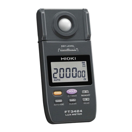
Hioki FT3424 Instruction Manual
Lux meter
Hide thumbs
Also See for FT3424:
- Instruction manual (166 pages) ,
- Instruction manual (132 pages) ,
- Instruction manual (83 pages)
Table of Contents
Advertisement
Quick Links
Download this manual
See also:
Instruction Manual
Advertisement
Table of Contents

Related Manuals for Hioki FT3424


Summary of Contents for Hioki FT3424
- Page 1 FT3424 FT3425 LUX METER Instruction Manual Scan this code to watch an instructional video. Carrier charges may apply. Jan. 2018 Revised edition 4 FT3424A980-04 1.800.561.8187 information@itm.com www. .com...
-
Page 2: Table Of Contents
Contents Introduction .................1 Verifying Package Contents ..........2 Options (Sold Separately) ..........3 Safety Notes ................5 Usage Notes ................8 Overview Overview and Features .........13 Parts Names and Functions ......14 LCD ..............19 Measurement Methods ........23 Inserting/Replacing Batteries ......24 Attaching the Strap ........26 Inspection Before Use ........28 Making Measurements ........29 Selecting the Measurement Range ....33 Applied Functionality... - Page 3 Contents Limiting Battery Consumption (Auto Power OFF Function) ......42 Saving Measured Values (Memory Function) ........44 Saving the measured value (MEM) ......44 Reading the saved measured values (READ) ..45 Deleting the most recently saved measured value (CLEAR) ............46 Deleting all the saved measured values ....
- Page 4 Repair, Inspection, and Cleaning ....67 Troubleshooting ..........68 Error Display ..........70 Display Messages .........71 Appendix Appx.1 Appx. 1 Recommended Levels of Illumination (Reference) ........Appx.1 Appx. 2 Sensor Characteristics Graphs ..Appx.3 Relative Spectral Response Characteristics in the Visible Spectrum ..........Appx.3 Angled Incident Light Characteristics ....Appx.4 Appx.
-
Page 5: Introduction
Introduction Introduction Thank you for purchasing the HIOKI FT3424, FT3425 Lux Meter. To obtain maximum performance from the product, please read this ® Only the FT3425 has the Bluetooth communication function. Using this function enables smart phones and tablets to view and record measurement data. -
Page 6: Verifying Package Contents
In particular, check the accessories, operation keys of the panel, and connectors. If damage is evident, or if it fails to operate according to Check the package contents as follows. FT3424 or FT3425 LR6 Alkaline battery × 2 Carrying case... -
Page 7: Options (Sold Separately)
Options (Sold Separately) Options (Sold Separately) The following options are available for the instrument. Connection cable Use when positioning the sensor unit and display unit separately during use. L9820 Connection Cable (Length: 2 m) Output cords Required when using the instrument’s output functionality. L9094 Output Cord L9095 Output Cord (Length: 1.5 m, for use with... - Page 8 Options (Sold Separately) Carrying cases Handy for storing the instrument with the L9820 Connection Cable, L9094/ L9095/L9096 Output Cord, and USB cable. C0201 Carrying Case C0202 Carrying Case (semi-hard) (soft) * L 9820 Connection Cable cannot be stored. Measurement aid Attach the sensor unit or instrument to this convenient cart to measure between measurement locations.
-
Page 9: Safety Notes
Safety Notes Safety Notes The instrument is designed to conform to IEC 61010 Safety Standards, and has been thoroughly tested for safety prior to shipment. However, using the instrument in a way not described in this manual may negate the provided safety features. Before using the instrument, be certain to carefully read the following safety notes. - Page 10 Indicates DC (Direct Current). ® Bluetooth is a registered trademark of BluetoothSIG, Inc. (USA). The trademark is used by HIOKI E.E. CORPORATION underlicense. Symbols for various standards Indicates the Waste Electrical and Electronic Equipment Directive (WEEE Directive) in EU member states.
- Page 11 Safety Notes Screen display The screen of the instrument displays characters in the following manner. A B C D E F G H I J K L M N O P Q R S T U V W X Y Z 1 2 3 4 5 6 7 8 9 0 Different displays are used in the cases below.
-
Page 12: Usage Notes
Usage Notes Usage Notes Follow these precautions to ensure safe operation and to obtain the Before Use Verify that the instrument operates normally to ensure that no Installation For details on the operating temperature and humidity, see the WARNING Installing the instrument in inappropriate locations may cause a malfunction of instrument or may give rise to an accident. - Page 13 Usage Notes Handling the cables and cords CAUTION Before use, verify that the insulation on cables and cords is not damaged and that no metal is exposed. not be able to make accurate measurements or send/ receive data otherwise. Avoid stepping on or pinching the cables and cords, which could damage the cable insulation.
- Page 14 Usage Notes IMPORTANT cable may result in incorrect measurements due to poor connection or other reasons. When measuring illuminance underneath a standard lighting voltage or to the surrounding environment (for example, a person’s shadow). Exercise care concerning these factors when performing measurement. The LCD includes a backlight for use when making measurements in dim locations.
- Page 15 Keep the disc inside a protective case and do not expose to direct sunlight, high temperature, or high humidity. Hioki is not liable for any issues your computer system experiences in the course of using this disc. Precautions during shipment Observe the following during shipment.
-
Page 16: Overview
Overview 1.1 Overview and Features The instrument is a multifunctional, high-precision lux meter which ensures durability. equipment management. Wide-range illuminance measurement (0.00 to 200000 Illuminance sensor Use the display unit and sensor unit separately that the instrument’s sensitivity L9820 Connection Cable to wavelength approximates (option) the response of the human... -
Page 17: Parts Names And Functions
Parts Names and Functions 1.2 Parts Names and Functions Front/Right Side Sensor Illuminance sensor (p. 29) Reference USB terminal level (mini B type) indication (p. 19) terminal (p. 47) Operation (p. 15) Strap hole (p. 26) The instrument can be separated into the sensor unit and display unit. (p. - Page 18 Parts Names and Functions FT3424 FT3425 1.800.561.8187 information@itm.com www. .com...
- Page 19 Parts Names and Functions Turn on the Press and hold instrument Press for at least 1 while holding second down – Turn on the Turn off the instrument. instrument. Retains the Start timer hold Cancels the measured value or function (p. 35) auto power off cancels retention of Automatically retain...
-
Page 20: Lcd
Parts Names and Functions Turn on the Press and hold instrument Press for at least 1 while holding second down Saves the Continuously Displays all the measured increases the memory indicators on the values in internal (p. 45) LCD. memory. (p. 44) Increases the *1, *2 memory No. - Page 21 Parts Names and Functions Rear Mounting thread Use when mounting the sensor unit on a tripod, a monopod, or the Z5023 Extension Cart. The hole is located exactly behind the center point of the illuminance sensor on the front of the sensor unit.
- Page 22 For message displays and error displays, see “5.3 Error Display” (p. 70), and “5.4 Display Messages” (p. 71). Holds the measured value. (p. 30, p. 35) Communicating with the USB. (p. 49) The memory function is activated. (p. 44) The instrument is in read mode, allows viewing the measured values stored in its internal memory.
- Page 23 The output function is activated. (p. 47) Represents the unit used to measure illuminance (lux). The Bluetooth communication function is activated. (FT3425 only) (p. 51) When the measured value exceeds the maximum value in each range appears on the LCD. 1.800.561.8187 information@itm.com www.
- Page 24 Battery indicator Fully charged. As the battery charge diminishes, black charge bars disappear, one by one, from the left of the battery indicator. The batteries are almost out of charge. Have a new battery handy. (Appears) The batteries are exhausted. Replace with new batteries immediately.
-
Page 25: Measurement Methods
Measurement Methods Before using the instrument, be sure to read “Usage Notes” (p. 8). Installation and connection As necessary, have other optional items available and ready. Measurement Save the 付 録 End of the measurement 索 引 1.800.561.8187 information@itm.com www. .com... -
Page 26: Inserting/Replacing Batteries
Inserting/Replacing Batteries not function properly. Be careful to observe the battery polarity during installation. Do not use batteries after their recommended expiry date. the instrument, remove the batteries from the instrument if 1.800.561.8187 information@itm.com www. .com... - Page 27 Inserting/Replacing Batteries of charge. is no battery life remaining. Replace the batteries immediately. After use, be sure to turn off the instrument. Turn off the instrument. Press and hold to turn off the instrument. Remove all of the old batteries. Rear 付...
-
Page 28: Attaching The Strap
Attaching the Strap You can attach the included strap (for the instrument) and the strap for the sensor cap to the strap hole on the bottom of the display unit. Attach the strap securely to the instrument. If insecurely carrying. 1.800.561.8187 information@itm.com www. - Page 29 Attaching the Strap Strap (for the instrument) Strap for the sensor cap 付 録 索 引 1.800.561.8187 information@itm.com www. .com...
-
Page 30: Inspection Before Use
Inspection Before Use Verify that the instrument operates normally to ensure that no Check item The instrument is neither If it is damaged, it could not be measured The internal circuits are not accurately. Do not use the instrument but exposed. -
Page 31: Making Measurements
Making Measurements Put the sensor cap on. the illuminance sensor. Press to turn on the instrument. Press [ADJ] is displayed, and zero adjustment [ADJ] goes off. bring the sensor unit near the measuring location. 付 録 索 引 1.800.561.8187 information@itm.com www. - Page 32 measurement) Press to select the range. Range” (p. 33) Press and read the measured value. Pressing of the measured value. You can also retain the measured value after a set amount of time elapses. See: “3.1 Retaining the Measured Value after a Set Amount of Time 1.800.561.8187 information@itm.com...
- Page 33 Put the sensor cap on. When the measurement is and turn off the instrument. Press and hold to turn off the instrument. If zero adjustment is performed immediately after the instrument is turned on, several count digits may remain. In that case, perform zero adjustment again.
- Page 34 If you press sensor cap attached to the illuminance or greater), [CAP] Press again after attaching the sensor cap. [CAP] is displayed. 1.800.561.8187 information@itm.com www. .com...
-
Page 35: Selecting The Measurement Range
Selecting the Measurement Range 2.6 Selecting the Measurement Range The auto or manual range can be selected. Auto range the actual measurement. Manual range appears. (default setting) 付 録 索 引 1.800.561.8187 information@itm.com www. .com... - Page 36 Selecting the Measurement Range Press operation. ( goes off.) Each time 200000 20000 Press and hold 1.800.561.8187 information@itm.com www. .com...
-
Page 37: Applied Functionality
Applied Functionality 3.1 Retaining the Measured Value after a Set Amount of Time (Timer Hold Function) This section describes how to retain the measured value after a set amount of time has elapsed. The timer hold function is convenient when measuring low illuminance values, for example from emergency lighting or along an evacuation route. - Page 38 Retaining the Measured Value after a Set Amount of Time (Timer Hold Function) The measured value will be retained once the set amount of time has elapsed. appear, and a continuous beep sounds for 3 sec.) When is pressed again, the hold state is canceled, and the timer hold function is not activated.
-
Page 39: Undocking The Display Unit And Sensor Unit
Undocking the Display Unit and Sensor Unit 3.2 Undocking the Display Unit and Sensor Unit The display unit and sensor unit can be undocked. Turn off the instrument. Hold the display unit and sensor unit, and pull them gradually apart. Connect the display unit and sensor unit with the L9820 Connection Cable (option). -
Page 40: Mounting The Sensor Unit On A Tripod Or Monopod
Mounting the Sensor Unit on a Tripod or Monopod 3.3 Mounting the Sensor Unit on a Tripod or Monopod Mount the instrument on a commercially available tripod or monopod when making measurements with keeping height from the unit. Example: When mounted on a tripod When mounting the instrument on the tripod or monopod, turn the thread (not the sensor unit). -
Page 41: Using The Z5023 Extension Cart
Using the Z5023 Extension Cart 3.4 Using the Z5023 Extension Cart Mount the sensor unit or instrument on the Z5023 Extension Cart constant. CAUTION The length of the Z5023’s handle can be adjusted. Tighten the lock after adjustment and verify that the handle’s length has been securely set. - Page 42 Using the Z5023 Extension Cart Using the Extension Cart Using the L9820 Connection cable Using a smartphone (FT3424, FT3425) (FT3425 only) Display unit Model L9820 Handle Sensor unit Utility base 1.800.561.8187 information@itm.com www. .com...
- Page 43 Using the Z5023 Extension Cart Attaching the instrument Secure the instrument (using the hole on the back of the sensor Screw Z5023 Reference: Attaching a monopod (commercially available) Secure the instrument (using the hole on the back of the sensor unit) to the monopod, and the monopod to the Z5023 using the Screw 付...
-
Page 44: Limiting Battery Consumption (Auto Power Off Function)
3.5 Limiting Battery Consumption (Auto Power OFF Function) not been operated for approx. 10 minutes, the power turns off off function is set to enabled. ( appears.) When the auto power off function is enabled, on the LCD will before the instrument automatically turns off. To continuously use the instrument without turning off the power, press any key on the front panel. - Page 45 Disabling the auto power off function Press while holding down to turn on the instrument. The auto power off function is disabled. Check that dose not appear on the LCD. The auto power off function will be disabled until the instrument is turned off.
-
Page 46: Saving Measured Values (Memory Function)
Saving Measured Values (Memory Function) 3.6 Saving Measured Values (Memory Function) The measurement result can be saved and read using the memory function. Up to 99 measured values can be saved. You can also delete saved measured values. (p. 46) Measured values saved in the internal memory can be downloaded to a computer using the instrument’s USB communications capability. -
Page 47: Reading The Saved Measured Values (Read)
Saving Measured Values (Memory Function) Reading the saved measured values (READ) Memory No. Press and hold (READ). appear.) The instrument enters the read mode, which is used to read the measured values saved in the internal memory. Select the desired memory No. using . -
Page 48: Deleting The Most Recently Saved Measured Value (Clear)
Saving Measured Values (Memory Function) Deleting the most recently saved measured value (CLEAR) Memory No. Press and hold (READ). appear.) The instrument enters the read mode, which is used to read the measured values saved in the internal memory. Press and hold (CLEAR). -
Page 49: Logging Illuminance Data (Output Function)
3.7 Logging Illuminance Data (Output Function) You can connect the instrument to a logger or other recording instrument and have it generate voltage output based on the measured values. This functionality outputs a voltage of 1 mV DC for each effective count digit in the measured value. - Page 50 Press and hold to turn off the instrument. Connect the mini jack of the output cord (option) to the D/ A OUTPUT terminal of the right side of the instrument. (Set the recording instrument in advance.) Connect the other terminal of the output cord to the logger or other recording instrument.
-
Page 51: Communicating With The Pc
Communicating with the PC 3.8 Communicating with the PC Using the included USB cable, it is possible to transmit data to the PC or to control the instrument. accompany with the CD. Install the dedicated PC application software on the PC. Verify that Bluetooth communications functionality has been disabled. - Page 52 Communicating with the PC Verify that Bluetooth communications functionality has been disabled before connecting the USB cable. Connecting the USB cable while Bluetooth communications functionality remains enabled will prevent USB communications. Bluetooth communications functionality cannot be enabled or disabled while the USB cable is connected. When connecting a USB cable to the instrument, exercise care to orient the connector properly.
-
Page 53: Communicating With A Smart Phone Or Tablet (Ft3425 Only)
Communicating with a Smart Phone or Tablet (FT3425 only) 3.9 Communicating with a Smart Phone or Tablet (FT3425 only) ® The FT3425 supports the Bluetooth low energy. When the Bluetooth function is enabled, you can review and record measurement data and create measurement reports on mobile devices (iPhone, iPad, iPad Mini, iPad Pro, iPod Touch, and Android™... - Page 54 Communicating with a Smart Phone or Tablet (FT3425 only) The Bluetooth communications functionality setting (enabled or disabled) is retained by the instrument, even if it is turned off. appears when the Bluetooth function is activated. communications functionality enabled, Bluetooth communications will take precedence over USB communications.
-
Page 55: Installing The Smartphone Application
Communicating with a Smart Phone or Tablet (FT3425 only) Installing the smartphone application Android™ device. Then download and install the GENNECT Cross. Store, or a Google account to download the application from Google Play. For more information about how to register an account, contact the store at which you purchased your device. -
Page 56: Pairing The Application With The Lux Meter (Ft3425)
Communicating with a Smart Phone or Tablet (FT3425 only) Pairing the application with the lux meter (FT3425) paired with any instrument), the connection setup screen will be displayed. While the mobile device is displaying the connection setup screen, simply move it close to the FT3425 to automatically pair it with the instrument (the application can be paired with up to 8 instruments). -
Page 57: Making Measurements With The Bluetooth Function
Communicating with a Smart Phone or Tablet (FT3425 only) Making measurements with the Bluetooth function Select either [General Measurement] [illuminance Measurement] on the home screen and measure. For more information about each function, see the help function in the GENNECT Cross. General measurement measurement function measurement function... -
Page 58: Disabling The Buzzer
3.10 Disabling the Buzzer Turn off the power of the instrument when changing the settings. while holding down Press to turn on the instrument. [bP oFF] activated. When you release , the screen will return to the measured value display. ( goes off.) 1.800.561.8187 information@itm.com... -
Page 59: Turning On The Backlight
3.11 Turning On the Backlight The LCD includes a backlight for use when making measurements in dim locations. The backlight will activate automatically when the measured value is retained or when the measured value data stored in the internal memory is in read mode, both in low-light environments (approx. - Page 60 0.00 2000 20000 200000 1.800.561.8187 information@itm.com www. .com...
- Page 61 3000 1.800.561.8187 information@itm.com www. .com...
- Page 62 30° 60° 1.800.561.8187 information@itm.com www. .com...
- Page 63 1 mV 2000 20000 200000 1.800.561.8187 information@itm.com www. .com...
- Page 64 [b. Lo] 1.800.561.8187 information@itm.com www. .com...
- Page 65 5 V DC 1.800.561.8187 information@itm.com www. .com...
- Page 66 1.800.561.8187 information@itm.com www. .com...
- Page 67 1.800.561.8187 information@itm.com www. .com...
-
Page 68: Accuracy
Maintenance and Service 5.1 Repair, Inspection, and Cleaning Calibrations IMPORTANT Periodic calibration is necessary in order to ensure that the accuracy. The calibration interval for the instrument is 2 years. It is recommended to calibrate it every 2 years for accurate measurement. Backing up the data The instrument may be initialized (returned to the factory default settings) when it is repaired or calibrated. -
Page 69: Troubleshooting
When a malfunction of the instrument is suspected, check the information in “Before sending the instrument for repair” and then, if necessary, contact your authorized Hioki distributor or reseller. When sending the instrument for repair, remove the batteries and pack it carefully to prevent damage during transportation. -
Page 70: Characteristics
Troubleshooting Symptom Check and/or remedy Turning on the power Send the instrument for repair. brings up the error display. When nothing is connected, the error display appears. Frequently asked questions (FAQ) Question Solution Would like to perform Perform zero adjustment. zero adjustment. -
Page 71: Error Display
LCD, it is Err 02 Malfunction of the adjustment necessary to repair the data instrument. Contact your authorized Err 04 Malfunction of the memory data Hioki distributor or reseller. Bluetooth error Err 08 Malfunction of the hardware (FT3425 only) 1.800.561.8187 information@itm.com www. -
Page 72: Display Messages
Display Messages 5.4 Display Messages Display Description Reference Performing zero adjustment. p. 29 The batteries are exhausted. p. 24 Replace the batteries. Disabling the buzzer. p. 56 Zero adjustment cannot be performed p. 32 since the sensor cap in not attached. Attach the sensor cap. -
Page 73: Appx. 1 Recommended Levels Of Illumination (Reference)
Appendix Appx. 1 Recommended Levels of Illumination (Reference) Suitable levels of illuminance (according to the JIS standard Z 9110). Recommended Illuminance Place/work activity illuminance [ level [ 500 to 1000 Computer rooms, conference rooms, 300 to 750 reception rooms 200 to 500 Reception area, dining rooms, elevator halls 150 to 300 Pantries, locker rooms, restrooms... - Page 74 Schools Recommended Illuminance Place/work activity illuminance [ level [ Precision handicraft, precision experiment- 1000 750 to 1500 500 to 1000 Precision drawing or drafting Experiment demonstration rooms, library 300 to 750 200 to 500 cafeteria 75 to 150 Corridors, connecting corridors, entrance Appx.2 1.800.561.8187 information@itm.com...
-
Page 75: Appx. 2 Sensor Characteristics Graphs
The deviation from the comparative standards for luminosity is determined by the f ’ value of JIS standard C 1609-1:2006. Deviation from spectral luminous efficiency FT3424, FT3425 Wavelength [ nm ] The graph illustrates typical characteristics. Characteristics exhibited by individual products may vary slightly. Appx.3 1.800.561.8187... -
Page 76: Angled Incident Light Characteristics
In the instrument, the shape of the light sensor, hook etc. is so made that it can follow the cosine law closely. Ideal Characteristics cos ) FT3424, FT3425 [ ° ] Incident angle The graph illustrates typical characteristics. Characteristics exhibited by individual products may vary slightly. -
Page 77: Appx. 3 Other Characteristics
Appx. 3 Other Characteristics Color correction factor for a general light source relative to standard illuminant A Light source Fluorescent lamp F6 1.003 Fluorescent lamp F8 1.002 Fluorescent lamp F10 1.002 High-pressure sodium lamp 1.011 Metal halide lamp H1 1.002 Metal halide lamp H2 1.003 High-pressure mercury lamp... -
Page 78: Appx. 4 Dimensional Drawings
Appx. 4 Dimensional Drawings Unit : mm The FT3424 and FT3425 have the same dimensions. Center of the mounting thread Appx.6 1.800.561.8187 information@itm.com www. .com... -
Page 79: Wty1
16-01 EN WTY1 1.800.561.8187 information@itm.com www. .com...
Need help?
Do you have a question about the FT3424 and is the answer not in the manual?
Questions and answers