Hioki FT3424 Instruction Manual
Lux meter
Hide thumbs
Also See for FT3424:
- Instruction manual (166 pages) ,
- Instruction manual (132 pages) ,
- Instruction manual (166 pages)
Table of Contents
Advertisement
Quick Links
Download this manual
See also:
Instruction Manual
Advertisement
Table of Contents

Related Manuals for Hioki FT3424


Summary of Contents for Hioki FT3424
- Page 1 FT3424 FT3425 LUX METER Instruction Manual 99 Washington Street Melrose, MA 02176 Phone 781-665-1400 Toll Free 1-800-517-8431 Visit us at www.TestEquipmentDepot.com Jan. 2018 Revised edition 4 FT3424A980-04...
- Page 3 Introduction Introduction Thank you for purchasing the HIOKI FT3424, FT3425 Lux Meter. To obtain maximum performance from the product, please read this manual first, and keep it handy for future reference. ® Only the FT3425 has the Bluetooth communication function.
-
Page 4: Verifying Package Contents
In particular, check the accessories, operation keys of the panel, and connectors. If damage is evident, or if it fails to operate according to the specifications, contact your authorized Hioki distributor or reseller. Check the package contents as follows. FT3424 or FT3425 LR6 Alkaline battery ×... -
Page 5: Options (Sold Separately)
Options (Sold Separately) Options (Sold Separately) The following options are available for the instrument. Contact your authorized Hioki distributor or reseller when ordering. Connection cable Use when positioning the sensor unit and display unit separately during use. L9820 Connection Cable... - Page 6 Options (Sold Separately) Carrying cases Handy for storing the instrument with the L9820 Connection Cable, L9094/ L9095/L9096 Output Cord, and USB cable. C0202 Carrying Case C0201 Carrying Case (soft) (semi-hard) L9820 Connection Cable cannot be stored. Measurement aid Attach the sensor unit or instrument to this convenient cart to measure illuminance on floor surfaces while standing.
-
Page 7: Safety Notes
Safety Notes Safety Notes The instrument is designed to conform to IEC 61010 Safety Standards, and has been thoroughly tested for safety prior to shipment. However, using the instrument in a way not described in this manual may negate the provided safety features. Before using the instrument, be certain to carefully read the following safety notes. - Page 8 Indicates DC (Direct Current). ® Bluetooth is a registered trademark of BluetoothSIG, Inc. (USA). The trademark is used by HIOKI E.E. CORPORATION underlicense. Symbols for various standards Indicates the Waste Electrical and Electronic Equipment Directive (WEEE Directive) in EU member states.
-
Page 9: Screen Display
Safety Notes Screen display The screen of the instrument displays characters in the following manner. A B C D E F G H I J K L M N O P Q R S T U V W X Y Z 1 2 3 4 5 6 7 8 9 0 Different displays are used in the cases below. -
Page 10: Usage Notes
Before Use Verify that the instrument operates normally to ensure that no damage occurred during storage or shipping. If you find any damage, contact your authorized Hioki distributor or reseller. Installation For details on the operating temperature and humidity, see the specifications.(p. - Page 11 Usage Notes Handling the cables and cords CAUTION • Before use, verify that the insulation on cables and cords is not damaged and that no metal is exposed. If you find any damage, replace the cable or cord with those specified by our company, as the instrument will not be able to make accurate measurements or send/ receive data otherwise.
- Page 12 Usage Notes IMPORTANT • Use only the specified L9820 Connection Cable when using the display unit and sensor unit separately. Using a non-specified cable may result in incorrect measurements due to poor connection or other reasons. • When measuring illuminance underneath a standard lighting fixture, the display may not stabilize.
- Page 13 • Keep the disc inside a protective case and do not expose to direct sunlight, high temperature, or high humidity. • Hioki is not liable for any issues your computer system experiences in the course of using this disc. Precautions during shipment Observe the following during shipment.
- Page 14 Usage Notes...
-
Page 15: Overview And Features
Overview 1.1 Overview and Features The instrument is a multifunctional, high-precision lux meter which ensures durability. Engineered for use in a wide range of fields and settings, including with lighting equipment, in lighting work, and in equipment management. Wide-range illuminance measurement (0.00 to 200000 Illuminance sensor Use the display unit and... -
Page 16: Parts Names And Functions
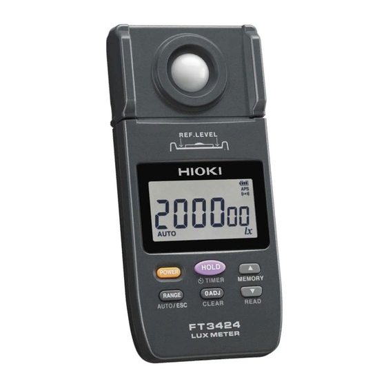
Parts Names and Functions 1.2 Parts Names and Functions Front/Right Side Sensor Illuminance sensor (p. 29) Reference USB terminal level (mini B type) indication LCD (p. 19) D/A OUTPUT terminal (p. 47) Operation keys (p. 15) Strap hole (p. 26) The instrument can be separated into the sensor unit and display unit. - Page 17 Parts Names and Functions Operation keys FT3424 FT3425...
- Page 18 Parts Names and Functions Turn on the Press and hold instrument Press for at least 1 while holding second down – Turn on the Turn off the instrument. instrument. Retains the Start timer hold Cancels the measured value or function (p. 35) auto power off cancels retention of Automatically retain...
- Page 19 Parts Names and Functions Turn on the Press and hold instrument Press for at least 1 while holding second down • Saves the Continuously Displays all the measured increases the memory indicators on the values in internal (p. 45) LCD. memory.
- Page 20 Parts Names and Functions Rear Mounting thread Use when mounting the sensor unit on a tripod, a monopod, or the Z5023 Extension Cart. The hole is located exactly behind the center point of the illuminance sensor on the front of the sensor unit.
- Page 21 1.3 LCD For message displays and error displays, see “5.3 Error Display” (p. 70), and “5.4 Display Messages” (p. 71). Holds the measured value. (p. 30, p. 35) Communicating with the USB. (p. 49) The memory function is activated. (p. 44) The instrument is in read mode, allows viewing the measured values stored in its internal memory.
- Page 22 The output function is activated. (p. 47) Represents the unit used to measure illuminance (lux). The Bluetooth communication function is activated. (FT3425 only) (p. 51) When the measured value exceeds the maximum value in each range The maximum displayable value flashes, appears on the LCD.
-
Page 23: Battery Indicator
Battery indicator Fully charged. As the battery charge diminishes, black charge bars disappear, one by one, from the left of the battery indicator. The batteries are almost out of charge. Have a new battery handy. (Appears) The batteries are exhausted. Replace with new batteries immediately. -
Page 25: Installation And Connection
Measurement Methods 2.1 Measurement Workflow Before using the instrument, be sure to read “Usage Notes” (p. 8). Installation and connection Insert the batteries with the sensor cap on. (p. 24) As necessary, have other optional items Perform the startup check. (p. 28) available and ready. -
Page 26: Inserting/Replacing Batteries
Inserting/Replacing Batteries 2.2 Inserting/Replacing Batteries Before using the instrument first time, insert two LR6 alkaline batteries. Before measurements, check that the battery level is sufficient. When the battery charge is low, replace the batteries. Nickel-metal hydride batteries Nickel-metal hydride batteries can be used. However, the discharge characteristic of these batteries is different from that of alkaline batteries. - Page 27 Inserting/Replacing Batteries • The indicator appears when the batteries are almost out of charge. Have new batteries handy. • When the indicator appears or flashes, there is no battery life remaining. Replace the batteries immediately. • During USB communications and while the instrument is connected to USB bus power, the battery indicator goes off.
-
Page 28: Attaching The Strap
Attaching the Strap 2.3 Attaching the Strap You can attach the included strap (for the instrument) and the strap for the sensor cap to the strap hole on the bottom of the display unit. CAUTION Attach the strap securely to the instrument. If insecurely attached, the instrument may fall and be damaged when carrying. - Page 29 Attaching the Strap When attaching both straps Strap (for the instrument) Strap for the sensor cap 付 録 索 引...
-
Page 30: Inspection Before Use
2.4 Inspection Before Use Verify that the instrument operates normally to ensure that no damage occurred during storage or shipping. If you find any damage, contact your authorized Hioki distributor or reseller. Appearance check of the instrument Action Check item •... -
Page 31: Making Measurements
Making Measurements 2.5 Making Measurements Turn on the instrument with the Put the sensor cap on. included sensor cap attached to the illuminance sensor. A value will be displayed on the LCD. Press to turn on the instrument. Press [ADJ] is displayed, and zero adjustment of all ranges will be performed. - Page 32 Making Measurements (To use a particular range to make a measurement) Press to select the range. See: “2.6 Selecting the Measurement Range” (p. 33) Read the measured value when it stabilizes. (When retaining the measured value) Press and read the measured value.
- Page 33 Making Measurements Put the sensor cap on. When the measurement is finished, put the sensor cap on and turn off the instrument. Press and hold to turn off the instrument. • is displayed when the measuring range is exceeded. • If zero adjustment is performed immediately after the instrument is turned on, several count digits may remain.
- Page 34 Making Measurements is pressed without the sensor cap attached without the included If you press sensor cap attached to the illuminance sensor (when the count is equivalent to 1 [CAP] will be displayed on the or greater), LCD. Press again after attaching the sensor cap.
-
Page 35: Selecting The Measurement Range
Selecting the Measurement Range 2.6 Selecting the Measurement Range The auto or manual range can be selected. • Auto range Sets the optimum range automatically in accordance with the actual measurement. (Disabled when the output function (OUTPUT) is in use.) •... - Page 36 Selecting the Measurement Range Measuring with the manual range Press The instrument will switch from the auto range to manual range, which will be fixed to the range that was selected during auto-range operation. ( goes off.) is pressed, the range is specified. Each time →...
-
Page 37: Applied Functionality
Applied Functionality 3.1 Retaining the Measured Value after a Set Amount of Time (Timer Hold Function) This section describes how to retain the measured value after a set amount of time has elapsed. The timer hold function is convenient when measuring low illuminance values, for example from emergency lighting or along an evacuation route. - Page 38 Retaining the Measured Value after a Set Amount of Time (Timer Hold Function) The measured value will be retained once the set amount of time has elapsed. appear, and a continuous beep sounds for 3 sec.) When is pressed again, the hold state is canceled, and the timer hold function is not activated.
-
Page 39: Undocking The Display Unit And Sensor Unit
Undocking the Display Unit and Sensor Unit 3.2 Undocking the Display Unit and Sensor Unit The display unit and sensor unit can be undocked. Turn off the instrument. Hold the display unit and sensor unit, and pull them gradually apart. Connect the display unit and sensor unit with the L9820 Connection Cable (option). -
Page 40: Mounting The Sensor Unit On A Tripod Or Monopod
Mounting the Sensor Unit on a Tripod or Monopod 3.3 Mounting the Sensor Unit on a Tripod or Monopod Mount the instrument on a commercially available tripod or monopod when making measurements with keeping height from the floor surface. Use the mounting thread* on the back of the sensor unit. -
Page 41: Using The Z5023 Extension Cart
Using the Z5023 Extension Cart 3.4 Using the Z5023 Extension Cart Mount the sensor unit or instrument on the Z5023 Extension Cart to measure illuminance at the floor surface while standing. The cart can be easily moved between measurement locations. In addition, a monopod can be attached to keep height from the floor surface constant. - Page 42 Using the Z5023 Extension Cart Using the Extension Cart Using the L9820 Connection cable Using a smartphone (FT3424, FT3425) (FT3425 only) Display unit Model L9820 Instrument Handle Sensor unit Utility base...
- Page 43 Using the Z5023 Extension Cart Attaching the instrument Secure the instrument (using the hole on the back of the sensor unit) to the Z5023 with the included screw*. * Thread size: 1/4” (ISO 1222) Screw Instrument Z5023 Reference: Attaching a monopod (commercially available) Secure the instrument (using the hole on the back of the sensor unit) to the monopod, and the monopod to the Z5023 using the...
-
Page 44: Limiting Battery Consumption (Auto Power Off Function)
Limiting Battery Consumption (Auto Power OFF Function) 3.5 Limiting Battery Consumption (Auto Power OFF Function) This function limits the battery consumption. If the instrument has not been operated for approx. 10 minutes, the power turns off automatically. In the original setting (default setting), the auto power off function is set to enabled. - Page 45 Limiting Battery Consumption(Auto Power OFF Function) Disabling the auto power off function If the instrument is on, turn it off. Press while holding down to turn on the instrument. The auto power off function is disabled. Check that dose not appear on the LCD. The auto power off function will be disabled until the instrument is turned off.
-
Page 46: Saving Measured Values (Memory Function)
Saving Measured Values (Memory Function) 3.6 Saving Measured Values (Memory Function) The measurement result can be saved and read using the memory function. Up to 99 measured values can be saved. You can also delete saved measured values. (p. 46) Measured values saved in the internal memory can be downloaded to a computer using the instrument’s USB communications capability. -
Page 47: Reading The Saved Measured Values (Read)
Saving Measured Values (Memory Function) Reading the saved measured values (READ) Memory No. Press and hold (READ). appear.) The instrument enters the read mode, which is used to read the measured values saved in the internal memory. Select the desired memory No. using . -
Page 48: Deleting The Most Recently Saved Measured Value (Clear)
Saving Measured Values (Memory Function) Deleting the most recently saved measured value (CLEAR) Memory No. Press and hold (READ). appear.) The instrument enters the read mode, which is used to read the measured values saved in the internal memory. Press and hold (CLEAR). -
Page 49: Logging Illuminance Data (Output Function)
Logging Illuminance Data (Output Function) 3.7 Logging Illuminance Data (Output Function) You can connect the instrument to a logger or other recording instrument and have it generate voltage output based on the measured values. This functionality outputs a voltage of 1 mV DC for each effective count digit in the measured value. - Page 50 Logging Illuminance Data (Output Function) Press and hold to turn off the instrument. Connect the mini jack of the output cord (option) to the D/ A OUTPUT terminal of the right side of the instrument. (Set the recording instrument in advance.) Connect the other terminal of the output cord to the logger or other recording instrument.
-
Page 51: Communicating With The Pc
Communicating with the PC 3.8 Communicating with the PC Using the included USB cable, it is possible to transmit data to the PC or to control the instrument. For details, see the communications specifications which accompany with the CD. Install the dedicated PC application software on the PC. Verify that Bluetooth communications functionality has been disabled. - Page 52 Communicating with the PC • Verify that Bluetooth communications functionality has been disabled before connecting the USB cable. Connecting the USB cable while Bluetooth communications functionality remains enabled will prevent USB communications. • Bluetooth communications functionality cannot be enabled or disabled while the USB cable is connected.
-
Page 53: Communicating With A Smart Phone Or Tablet (Ft3425 Only)
Communicating with a Smart Phone or Tablet (FT3425 only) 3.9 Communicating with a Smart Phone or Tablet (FT3425 only) ® The FT3425 supports the Bluetooth low energy. When the Bluetooth function is enabled, you can review and record measurement data and create measurement reports on mobile devices (iPhone, iPad, iPad Mini, iPad Pro, iPod Touch, and Android™... - Page 54 Communicating with a Smart Phone or Tablet (FT3425 only) • The Bluetooth communications functionality setting (enabled or disabled) is retained by the instrument, even if it is turned off. • appears when the Bluetooth function is activated. • flashes when the instrument is connected to a mobile device. •...
-
Page 55: Installing The Smartphone Application
Waves” or go to our website. • The FT3425 availability is limited to certain countries. For more information, contact your authorized Hioki distributor or reseller. • Bluetooth communications range varies greatly with distance from obstructions (walls, metal obstruction, etc.) as well as distance from the floor or ground. -
Page 56: Pairing The Application With The Lux Meter (Ft3425)
Communicating with a Smart Phone or Tablet (FT3425 only) Pairing the application with the lux meter (FT3425) • When the application is launched for the first time (before being paired with any instrument), the connection setup screen will be displayed. •... -
Page 57: Making Measurements With The Bluetooth Function
Communicating with a Smart Phone or Tablet (FT3425 only) Making measurements with the Bluetooth function [General Measurement] [illuminance Select either Measurement] on the home screen and measure. For more information about each function, see the help function in the GENNECT Cross. Illuminance Illuminance General measurement... -
Page 58: Disabling The Buzzer
Disabling the Buzzer 3.10 Disabling the Buzzer The buzzer sound is enabled when factory default settings. Turn off the power of the instrument when changing the settings. while holding down Press to turn on the instrument. [bP oFF] is displayed, and the buzzer is not activated. -
Page 59: Turning On The Backlight
Turning On the Backlight 3.11 Turning On the Backlight The LCD includes a backlight for use when making measurements in dim locations. The backlight will activate automatically when the measured value is retained or when the measured value data stored in the internal memory is in read mode, both in low-light environments (approx. - Page 60 Disabling the Buzzer...
-
Page 61: Basic Specifications
Specifications 4.1 Basic Specifications Classifications Grade JIS C 1609-1: 2006 General Class AA Display • Display LCD 4 digits • Effective display digits 2000 counts • Display unit (lux) • Display update rate 500 ms ± 20 ms Measurement Range Measuring range Display steps ranges... -
Page 62: Measurement Specifications
Measurement Specifications 4.2 Measurement Specifications Accuracy Linearity ±2% rdg. (Multiply by 1.5 for display values in excess of 3000 (Add ±1 dgt. for display values that are less than 1/3 of the range.) Accuracy guarantee The display unit and sensor unit must bear the conditions same collation No. - Page 63 Measurement Specifications Characteristics Angled Systematic deviation f : 3% or less incident light Deviation from cosine characteristics: characteristics Angle Deviation from cosine characteristics ±2% 30° ±7% 60° 80° ±25% Response time Auto range: 5 seconds or less Manual range: 2 seconds or less Temperature Deviation from the value measured at 23°C (73.4°F) characteristics...
-
Page 64: Output Specifications
Output Specifications 4.3 Output Specifications Output method D/A output Output level 2 V/ range f.s. 2.5 V is output when the range f.s. is exceeded. Resolution 1 mV Range Output rate 1 mV DC / 0.01 1 mV DC / 0.1 1 mV DC / 1 2000 1 mV DC / 10... -
Page 65: Functional Specifications
Functional Specifications 4.4 Functional Specifications Hold function Retains the measured value. Timer hold Retains the measured value after the set timer time function has elapsed after executing. Select and set the timer time from 5, 10, 15, 20, 30, 45, 60 seconds. Memory function Up to 99 measured data can be saved. -
Page 66: General Specifications
4.5 General Specifications Product warranty 3 years period Light receiving Silicon photo diode element Interface USB 2.0 (FT3424, FT3425), Bluetooth 4.0LE (FT3425 only) Operating -10°C to 40°C (14°F to 104°F), 80% RH or less (no temperature and condensation) humidity Storage -20°C to 50°C (-4°F to 122°F), 80% RH or less (no... - Page 67 IP40 (EN60529) waterproof To avoid any failure, do not allow the instrument to get wet. If the instrument gets wet, have your authorized Hioki distributor or reseller inspect or repair it, if necessary. Accessories • Instruction manual • Precautions concerning use of equipment that emits radio waves (FT3425 only) •...
-
Page 68: Bluetooth Communication
Bluetooth Communication Specifications (FT3425 only) 4.6 Bluetooth Communication Specifications (FT3425 only) Display of measured values on a smartphone or tablet Instrument Bluetooth communications function disabled: goes off operation Bluetooth communications function enabled: appears Bluetooth communications active: flashes (The enabled/disabled setting is stored in the instrument’s memory.) Interface Bluetooth 4.0LE (... -
Page 69: Maintenance And Service
Maintenance and Service 5.1 Repair, Inspection, and Cleaning Calibrations IMPORTANT Periodic calibration is necessary in order to ensure that the instrument provides correct measurement results of the specified accuracy. The calibration interval for the instrument is 2 years. It is recommended to calibrate it every 2 years for accurate measurement. -
Page 70: Troubleshooting
• When a malfunction of the instrument is suspected, check the information in “Before sending the instrument for repair” and then, if necessary, contact your authorized Hioki distributor or reseller. • When sending the instrument for repair, remove the batteries and pack it carefully to prevent damage during transportation. -
Page 71: Frequently Asked Questions (Faq)
Troubleshooting Symptom Check and/or remedy Turning on the power Send the instrument for repair. Refer to “5.3 Error Display” (p. 70) brings up the error display. When nothing is connected, the error display appears. Frequently asked questions (FAQ) Question Solution Would like to perform Perform zero adjustment. -
Page 72: Error Display
LCD, it is Malfunction of the adjustment necessary to repair the data instrument. EEPROM error Err 04 Contact your authorized Malfunction of the memory data Hioki distributor or reseller. Bluetooth error Err 08 Malfunction of the hardware (FT3425 only) -
Page 73: Display Messages
Display Messages 5.4 Display Messages Display Description Reference Performing zero adjustment. p. 29 The batteries are exhausted. p. 24 Replace the batteries. Disabling the buzzer. p. 56 Zero adjustment cannot be performed p. 32 since the sensor cap in not attached. Attach the sensor cap. - Page 74 Error Display...
-
Page 75: Appx. 1 Recommended Levels Of Illumination (Reference)
Appendix Appx. 1 Recommended Levels of Illumination (Reference) Suitable levels of illuminance (according to the JIS standard Z 9110). Offices Recommended Illuminance Place/work activity illuminance [ level [ 500 to 1000 Design rooms, offices, board rooms Computer rooms, conference rooms, 300 to 750 reception rooms 200 to 500... - Page 76 Schools Recommended Illuminance Place/work activity illuminance [ level [ Precision handicraft, precision experiment- 1000 750 to 1500 500 to 1000 Precision drawing or drafting Experiment demonstration rooms, library 300 to 750 reading rooms, nurse’s office, kitchen Classrooms, gymnasium, office rooms, 200 to 500 cafeteria 75 to 150...
-
Page 77: Appx. 2 Sensor Characteristics Graphs
The deviation from the comparative standards for luminosity is determined by the f ’ value of JIS standard C 1609-1:2006. Deviation from spectral luminous efficiency FT3424, FT3425 Wavelength [ nm ] The graph illustrates typical characteristics. Characteristics exhibited by individual products may vary slightly. Appx.3... -
Page 78: Angled Incident Light Characteristics
In the instrument, the shape of the light sensor, hook etc. is so made that it can follow the cosine law closely. Ideal Characteristics cos θ) FT3424, FT3425 [ ° ] Incident angle The graph illustrates typical characteristics. Characteristics exhibited by individual products may vary slightly. -
Page 79: Appx. 3 Other Characteristics
Appx. 3 Other Characteristics Color correction factor for a general light source relative to standard illuminant A Light source Fluorescent lamp F6 1.003 Fluorescent lamp F8 1.002 Fluorescent lamp F10 1.002 High-pressure sodium lamp 1.011 Metal halide lamp H1 1.002 Metal halide lamp H2 1.003 High-pressure mercury lamp... -
Page 80: Appx. 4 Dimensional Drawings
Appx. 4 Dimensional Drawings Unit : mm The FT3424 and FT3425 have the same dimensions. REF.LEVEL φ20 Center of the mounting thread Appx.6... - Page 81 16-01 EN WTY1...
- Page 82 HIOKI Test Equipment Depot - 800.517.8431 99 Washington Street, Melrose, MA 02176 TestEquipmentDepot.com 1801EN Edited and published by H!OK! EE CORPORATION Printed in Japan ·CE declarations of conrorrnity can be downloaded ·rrorn our web:iiite. ·Contents subject to change without notice.
Need help?
Do you have a question about the FT3424 and is the answer not in the manual?
Questions and answers