Table of Contents
Advertisement
Advertisement
Table of Contents

Related Manuals for Keysight E3631A


Summary of Contents for Keysight E3631A
-
Page 1: Dc Power Supply
Keysight E3631A Triple Output DC Power Supply Service Guide... -
Page 2: Copyright Notice
Conformity. understood and met. where in the EULA. Keysight shall be under no obligation to update, revise or otherwise modify the Software. With WARNING respect to any technical data as defined by FAR 2.101, pursuant to FAR... -
Page 3: Warranty Service
(becomes a part of) other Keysight products. During the warranty period, Keysight will, at its option, either repair or replace products which prove to be defective. The warranty period begins on the date of delivery or on the date of installation if installed by Keysight. -
Page 4: Limitation Of Warranty
The information contained in this document is subject to change without notice. To the extent allowed by local law, Keysight makes no warranty of any kind with regard to this material, including, but not limited to, the implied warranties of merchantability and fitness for a particular purpose. - Page 5 To the extent allowed by local law, Keysight shall not be liable for errors contained herein or for incidental or consequential damages in connection with the furnishing, performance, or use of this material. No part of this document may be photocopied, reproduced, or translated to another language without the prior written consent of Keysight.
- Page 6 Direct current (DC) information) Protective conductor terminal Alternating current (AC) Earth (ground) terminal Out position of a bi-stable push control Frame or chassis terminal In position of a bi-stable push control Positive binding post Negative binding post Keysight E3631A Service Guide...
- Page 7 Do not install substitute parts or perform any unauthorized mod ification to WARNING the prod uct. Return the prod uct to Keysight Sales and Service Office for service and repair to ensure that safety features are maintained. Keysight E3631A Service Guide...
- Page 8 NMB-001 du Canada. environment outside of the home. This instrument complies with the WEEE Directive (2002/96/EC) marking requirement. This affixed product label indicates that you must not discard this electrical or electronic product in domestic household waste. Keysight E3631A Service Guide...
-
Page 9: Waste Electrical And Electronic Equipment (Weee) Directive
To return this unwanted instrument, contact your nearest Keysight Service Center, or visit http://about.keysight.com/en/companyinfo/environment/takeback.shtml for more information. Sales and Technical Support To contact Keysight for sales and technical support, refer to the support links on the following Keysight websites: – www.keysight.com/find/powersupply (product-specific information and support, software and documentation updates) –... -
Page 10: Keysight E3631A Triple Output Dc Power Supply
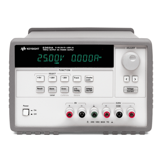
Keysight E3631A Triple Output DC Power Supply The Keysight Technologies E3631A is a high performance 80 watt-triple output DC power supply with GPIB and RS-232 interfaces. The combination of bench-top and system features in this power supply provides versatile solutions for your design and test requirements. -
Page 11: The Front Panel At A Glance
I/O Configuration / Secure key Tracking enable/disable key Output On/Off key Display limit key Control knob Recall operating state key Resolution selection keys Store operating state / Local key Voltage/current adjust selection key Error / Calibrate key Keysight E3631A Service Guide... - Page 12 You can enable the "calibration mode" by holding down this key when you turn on the power supply. You can use it as the "Secure" or "Unsecure" key when the power supply is in the calibration mode. Keysight E3631A Service Guide...
-
Page 13: Front-Panel Voltage And Current Settings
All front panel keys and controls can be disabled with remote interface NOTE commands. The Keysight E3631A must be in "Local" mode for the front panel keys and controls to function. Keysight E3631A Service Guide... -
Page 14: Display Annunciators
The displayed output is unregulated (output is neither CV nor CC). The displayed output is in constant-voltage mode. The displayed output is in constant-current mode. To review the display annunciators, hold down “Display Limit” key as you turn on the power supply. Keysight E3631A Service Guide... -
Page 15: The Rear Panel At A Glance
– Select the GPIB or RS-232 interface (see chapter 3 in User's Guide). – Set the GPIB bus address (see chapter 3 in User's Guide). – Set the RS-232 baud rate and parity (see chapter 3 in User's Guide). Keysight E3631A Service Guide... - Page 16 Environmental cond ition Requirements Operating condition – 0 °C to 40 °C Temperature Storage condition – –20 °C to 70 °C Humid ity Up to 80% RH Al titude Up to 2000 m Installation category Pollution degree Keysight E3631A Service Guide...
-
Page 17: In This Book
Keysight Technologies for servicing, or for servicing it yourself. Chapter 6, "Component Drawings" contains the component locator diagrams. If you have questions relating to the operation of the power supply, call 1-800-829-4444 in the United States, or contact your nearest Keysight Technologies Sales Office. Keysight E3631A Service Guide... - Page 18 THIS PAGE HAS BEEN INTENTIONALLY LEFT BLANK. Keysight E3631A Service Guide...
-
Page 19: Table Of Contents
........8 Keysight E3631A Triple Output DC Power Supply . - Page 20 ......64 Performance test record for Keysight E3631A ....70 Calibration security code .
- Page 21 E3631-60004 Component Locator for the Main Board — Bottom .122 Component Locator for the Main Board — Top (serial MY53xx6xxx) Component Locator for the Front Panel (serial MY53xx6xxx) ..124 Component Locator for the Main Board — Bottom (serial MY53xx6xxx) Keysight E3631A Service Guide...
- Page 22 THIS PAGE HAS BEEN INTENTIONALLY LEFT BLANK. Keysight E3631A Service Guide...
-
Page 23: Keysight E3631A Service Guide
List of Figures Figure 1-1 Dimensions of Keysight E3631A Power Supply ..30 Figure 3-1 Performance verification test setup ....52 Figure 3-2 Front panel terminal connection . -
Page 24: Keysight E3631A Service Guide
THIS PAGE HAS BEEN INTENTIONALLY LEFT BLANK. Keysight E3631A Service Guide... - Page 25 ......113 Table 3-2 Bias Supplies Voltages (MY53xx6xxx) ... .114 Keysight E3631A Service Guide...
- Page 26 THIS PAGE HAS BEEN INTENTIONALLY LEFT BLANK. Keysight E3631A Service Guide...
-
Page 27: Specifications
Keysight E3631A Triple Output DC Power Supply Service Guide Specifications The performance specifications are listed in the following pages. Specifications are warranted in the temperature range of 0 to 40°C with a resistive load. Supplemental characteristics, which are not warranted but are descriptions of performance determined either by design or testing. -
Page 28: Performance Specifications
Change in output voltage or current for any load change within ratings Vol tage <0.01% + 2 mV Current <0.01% + 250 mA Line regulation, ±(% of output + offset) Change in output voltage and current for any line change within ratings Keysight E3631A Service Guide... - Page 29 Readback Command : Maximum time to readback output by MEASure? command : <100 msec The Other Commands : < 50 msec Tracking accuracy The ±25V outputs track each other within ± (0.2% of output + 20 mV). Accuracy specifications are after an 1-hour warm-up and calibration at 25°C. Keysight E3631A Service Guide...
-
Page 30: Supplemental Characteristics
20 msec No load down 200 msec 400 msec 400 msec Isolation The 0-6V supply is isolated from the ±25V supply up to ±240 Vdc. Maximum isolation voltage from any terminal to chassis ground ±240 Vdc. Keysight E3631A Service Guide... - Page 31 Three (3) user-configurable stored states Recommended calibration interval 1 year Dimensions* 212.6 mmW x 132.6 mmH x 348.2 mmD (8.4 x 5.2 x 13.7 in) *See the next page for detailed information. Weight 8.2kg (18 lb) Shopping 11kg (24 lb) Keysight E3631A Service Guide...
-
Page 32: Figure 1-1 Dimensions Of Keysight E3631A Power Supply
Specifications Figure 1-1 Dimensions of Keysight E3631A power supply Keysight E3631A Service Guide... -
Page 33: Quick Start
Keysight E3631A Triple Output DC Power Supply Service Guide Quick Start... - Page 34 +6V annunciators will turn on. If, however, the power supply is remotely controlled, the Rmt annunciator will also turn on, and when the power supply is being addressed over GPIB interface, the Adrs annunciator will turn on. See Display Annunciators for more information. Keysight E3631A Service Guide...
-
Page 35: To Prepare The Power Supply For Use
(see the next page for detailed information). For 100 or 115 Vac operation, the correct fuse is 2.5 AT (Keysight part number 2110-0913) and for 230 Vac operation, the correct fuse is 2 AT (Keysight part number 2110-0587). - Page 36 3 Rotate the power-line voltage 4 Replace the power-line voltage selector until the correct voltage selector and the fuse-holder appears. assembly in the rear panel. Install the correct fuse and verify that the correct line voltage appears in the window. Keysight E3631A Service Guide...
-
Page 37: To Check The Rated Voltages Of The Power Supply
–25V annunciator will turn on. Repeat steps (3) and (4) to check the voltage function for the –25V supply. You can use the resolution selection keys to move the blinking digit to the right or left when setting the voltage. Keysight E3631A Service Guide... -
Page 38: To Check The Rated Currents Of The Power Supply
(actually, the voltmeter will show the voltage drop caused by the test lead). 6 Ensure that the current can be ad justed from zero to the maximum rated value. Adjust the knob until the ammeter indicates 0 amps and then until the ammeter indicates 5.0 amps. Keysight E3631A Service Guide... - Page 39 ERROR annunciator will turn on. See "Error Messages" for more information, starting on page 113 in chapter 5 of the User's Guide. You can use the resolution selection keys to move the blinking digit to the right or left when setting the current. Keysight E3631A Service Guide...
-
Page 40: To Use The Power Supply In Constant Voltage Mode
We recommend that you should set the display to "limit" mode to see the change of current limit value in constant voltage mode whenever adjusting the knob. Keysight E3631A Service Guide... - Page 41 You can use the resolution selection keys to move the blinking digit to the right or left when setting the voltage and current. Keysight E3631A Service Guide...
-
Page 42: To Use The Power Supply In Constant Current Mode
We recommend that you should set the display to "limit" mode to see the change of voltage limit value in constant current mode whenever adjusting the knob. Keysight E3631A Service Guide... - Page 43 You can use the resolution selection keys to move the blinking digit to the right or left when setting the voltage and current. Keysight E3631A Service Guide...
-
Page 44: To Use The Power Supply In Track Mode
NOTE +25V supply, choose a higher current limit for the +25V supply. If the CC annunciator is lit when the display is selected for the –25V supply, choose a higher current limit for the –25V supply. Keysight E3631A Service Guide... -
Page 45: To Store And Recall The Instrument State
“Store” key. The power supply returns to the normal operating mode and to the function pressed. 4 Save the operating state. The operating state is now stored. To recall the stored state, go to the following steps. Keysight E3631A Service Guide... - Page 46 7 Restore the operating state. The power supply should now be configured in the same state as when you stored the state on the previous steps. This message appears on the display for approximately 1 second. Keysight E3631A Service Guide...
-
Page 47: To Rack Mount The Power Supply
Option 1CM (P/N 5062-3957). Installation instructions and hardware are included with each rack-mounting kit. Any Keysight Technologies System II instrument of the same size can be rack-mounted beside the Keysight E3631A power supply. To rack mount the power supply, follow these procedures. - Page 48 Quick Start To remove the rear bumper, pull the bumper off from the top as there are protrusions on the sides and bottom of the cover. To rack mount a single instrument, order adapter kit 5063-9243. Keysight E3631A Service Guide...
- Page 49 Quick Start To rack mount two instruments of the same depth side-by-side, order lock-link kit 5061-9694 and flange kit 5063-9214. To install two instruments in a sliding support shelf, order suport shelf 5063-9256, and slide kit 1494-0015. Keysight E3631A Service Guide...
- Page 50 Quick Start THIS PAGE HAS BEEN INTENTIONALLY LEFT BLANK. Keysight E3631A Service Guide...
-
Page 51: Calibration Procedures
Keysight E3631A Triple Output DC Power Supply Service Guide Calibration Procedures This chapter contains procedures for verification of the power supply's performance and calibration (adjustment). The chapter is divided into the following sections: – Keysight Technologies Calibration Services – Calibration Interval –... -
Page 52: Keysight Technologies Calibration Services
1 year for any application. Keysight Technologies recommends that complete re-adjustment should always be performed at the calibration interval. This will increase your confidence that the Keysight E3631A will remain within specification for the next calibration interval. This criteria for re-adjustment provides the best long-term stability. -
Page 53: Recommended Test Equipment
The power supply must be unsecured prior to initiating the calibration procedure. A Keysight BASIC program for calibration over the GPIB interface is listed at the end of this chapter. -
Page 54: Test Considerations
– Performance Verification Tests These tests can be used to verify the power supply's specifications following repairs to specific circuits. The performance test procedures must be performed on each output. Keysight E3631A Service Guide... - Page 55 2 more seconds. You can also perform a self-test from the remote interface (see chapter 3 in the Keysight E3631A User's Guide). – If the self-test is successful, "PASS" is displayed on the front panel. – If the self-test fails, "FAIL" is displayed and the ERROR annunciator turns on. If...
-
Page 56: Measurement Techniques
Setup for most tests Most tests are performed at the front terminals as shown in the following figure. Measure the dc voltage directly at the (+) and (-) terminals on the front panel. Figure 3-1 Performance verification test setup Keysight E3631A Service Guide... -
Page 57: Figure 3-2 Front Panel Terminal Connection
Substitution of the electronic load requires minor changes to the test procedures in this chapter. Keysight E3631A Service Guide... - Page 58 GPIB or RS-232 controller. Complete instructions on front panel and remote programming are given in the Keysight E3631A User's Guide. Voltage and current values The full-scale and maximum values of each supply are listed below. You can use this table when you test CV and CC performance verification tests.
-
Page 59: Constant Voltage (Cv) Verifications
4 Record the output voltage reading on the digital voltmeter (DVM). The readings should be within the limits specified below for each output tested. Also, note that the CV, Adrs, Lmt, and Rmt annunciators are on. Keysight E3631A Service Guide... - Page 60 Programming Output Accuracy +6V Output 6 V ± 11 mV +25V Output 25 V ± 32.5 mV -25V Output -(25 V ± 32.5 mV) Keysight E3631A Service Guide...
- Page 61 The difference between the digital voltmeter readings in steps (3) and (4) is the CV load regulation. The difference of the readings during the immediate change should be within the limit specified below for each output tested. Keysight E3631A Service Guide...
- Page 62 The difference between the digital voltmeter readings in steps (5) and (6) is the CV line regulation. The difference of the readings during the immediate change should be within the limit specified below for each output tested. Keysight E3631A Service Guide...
- Page 63 5 Check that the front panel CV annunciator remains lit. If not lit, adjust the load down slightly. 6 Note that the waveform on the oscilloscope does not exceed the peak-to-peak limit of 2 mV for each of the three outputs. Keysight E3631A Service Guide...
-
Page 64: Figure 3-3 Peak-To-Peak Ripple/Noise Measurement Setup
3-4. The RMS voltage reading does not exceed the RMS limit of 0.35 mV for each of the three outputs. 8 Repeat steps (1) through (7) for the remaining outputs. Figure 3-3 Peak-to-peak ripple/noise measurement setup Keysight E3631A Service Guide... -
Page 65: Figure 3-4 Rms Ripple/Noise Measurement Setup
3 Turn on the power supply and select the output to be tested using the meter and adjust selection key on the front panel. Enable the outputs and set the display to the limit mode. When the display is in the limit mode, program the Keysight E3631A Service Guide... - Page 66 (t2-t1) of the transients at 15 mV from the base line is no more than 50 ?sec for each of the three outputs. 6 Repeat steps (1) through (5) for the remaining outputs. Keysight E3631A Service Guide...
-
Page 67: Figure 3-5 Transient Response Time
Calibration Procedures Figure 3-5 Transient response time Keysight E3631A Service Guide... -
Page 68: Constant Current (Cc) Verifications
0 A ± 10 mA +25V Output 0 A ± 4 mA -25V Output 0 A ± 4 mA 5 Readback the output current from the selected output over the remote interface by sending the command: MEAS:CURR? {P6V|P25V|N25V} Keysight E3631A Service Guide... - Page 69 9 Readback the output current from the selected output over the remote interface by sending the command: MEAS:CURR? {P6V|P25V|N25V} 10 Record the value displayed on the controller. This value should be within the limits specified below for each output tested. Keysight E3631A Service Guide...
- Page 70 Calibration Procedures Output Readback Accuracy ± 20 mA +6V Output A ± 5.5 mA +25V Output A ± 5.5 mA -25V Output 11 Repeat steps (1) through (10) for the remaining outputs. Keysight E3631A Service Guide...
- Page 71 The difference of the readings during the immediate change should be within the limit specified below for each output tested. Output Difference +6V Output 0.75 mA +25V Output 0.35 mA -25V Output 0.35 mA 5 Repeat steps (1) through (4) for the remaining outputs. Keysight E3631A Service Guide...
- Page 72 (6) is the load regulation current. The difference of the readings during the immediate change should be within the limit specified below for each output tested. Output Difference +6V Output 0.75 mA +25V Output 0.35 mA -25V Output 0.35 mA Keysight E3631A Service Guide...
- Page 73 The readings should be within the limit specified below for each output tested. Output Specification +6V Output 2 mA +25V Output 0.5 mA -25V Output 0.5 mA 5 Repeat steps (1) through (4) for the remaining outputs. Keysight E3631A Service Guide...
-
Page 74: Performance Test Record For Keysight E3631A
Calibration Procedures Performance test record for Keysight E3631A CV performance test record Specifications Test Description Actual Resul t Upper Limit Lower Limit CV Programming Accuracy @ 0 volts (DVM reading) +0.0050 V -0.0050 V +6V supply +0.0200 V -0.0200 V +25V supply +0.0200 V... - Page 75 CV Current Noise (Common Mode) +6V supply <1.5 mA for each of the three outputs +25V supply -25V supply Load Transient Response Time +6V supply <50 msec for each of three outputs +25V supply -25V supply Keysight E3631A Service Guide...
-
Page 76: Cc Performance Test Record
<0.35 mA -25V supply <0.35 mA CC Line Regulation Maximum change: +6V supply <0.75 mA +25V supply <0.35 mA -25V supply <0.35 mA CC Ripple/Noise <2 mA +6V supply <0.5 mA +25V supply <0.5 mA -25V supply Keysight E3631A Service Guide... -
Page 77: Calibration Security Code
– If you forget your security code, you can disable the security feature by adding a jumper inside the power supply, and then entering a new code. See the procedure in To unsecure the power supply for calibration in this chapter. Keysight E3631A Service Guide... - Page 78 Use the resolution selection keys to move left or right between digits. Use the knob to change the digits. Notice that the security code may be different if the security code has been changed from the default setting. 4 Unsecure the power supply. Keysight E3631A Service Guide...
- Page 79 6 Remove the short at JP1 . (An error occurs if not removed.) 7 7 Turn off and reassemble the power supply. Now you can enter a new security code. Be sure you take note of the new security code. Keysight E3631A Service Guide...
-
Page 80: Calibration Count
– The calibration message may contain up to 40 characters. – The calibration message is stored in non-volatile memory and does not change when power has been off or after a remote interface reset. Keysight E3631A Service Guide... -
Page 81: General Calibration/Adjustment Procedure
I HI V LO CAL SETUP 5 Voltage V HI -25V output I LO CAL SETUP 6 Current I HI You can terminate any CAL SETUP without changing its calibration constants by NOTE turning off power. Keysight E3631A Service Guide... - Page 82 6 Read the DVM and change the first voltage value on the display to match the measured voltage. For example, if the DVM reading is 0.0860 V, adjust the voltage to 0.0860 V using the knob and resolution selection keys. Keysight E3631A Service Guide...
- Page 83 "CAL SETUP 1" for the voltage calibration of the +6V supply again. *Connect an appropriate shunt (see Table 3-1) across the +6V supply's output terminals, and connect a digital voltmeter across the shunt resistor for the current calibration. Keysight E3631A Service Guide...
- Page 84 13 Read the DVM and change the second current value on the display to match the computed current (DVM reading ? by shunt resistance). For example, if the computed value is 4.999 A, adjust the current to 4.999 A using the knob and arrow keys. Keysight E3631A Service Guide...
- Page 85 You can also calibrate the output voltage and current of the -25V supply easily in the same manner. Notice that you should connect a shunt across (-) and (COM) terminals of the ±25V supply for the -25V supply current calibration. Keysight E3631A Service Guide...
-
Page 86: Aborting A Calibration In Progress
You can abort a calibration at any time by turning the power supply off from the front panel. When performing a calibration from the remote interface, you can abort a calibration by issuing a remote interface device clear message or by pressing the front-panel "Local" key. Keysight E3631A Service Guide... -
Page 87: Calibration Record For Keysight E3631A
Calibration Procedures Calibration record for keysight E3631A Measurement Supply being Step Calibration Description Mode (DVM) Ad justed Unsecure the power supply (see page 65). Turn on "CAL MODE"(simultaneously press "Calibrate" and "Power" keys) until a beep is heard. Move down menu to "CAL SETUP 1" (press "Calibrate" key). - Page 88 0.1? resistor; then press -25 supply "Calibrate" key). "I HI +0.950 A" appears on the display (change the display to match the computed current through 0.1? resistor; then press -25 supply "Calibrate" key). Keysight E3631A Service Guide...
-
Page 89: Error Messages
Calibration Procedures Error messages The following tables are abbreviated lists of error messages for the E3631A. The errors listed are the most likely errors to be encountered during calibration and adjustment. A more complete list of error messages and descriptions is contained in chapter 5 of the E3631A User's Guide. - Page 90 I/O processor does not respond I/O processor failed self-test Fan test failed System DAC test failed P6V hardware test failed P25V hardware test failed N25V hardware test failed This error message is only applicable for serial MY53xx6xxx. Keysight E3631A Service Guide...
-
Page 91: Calibration Error Messages
Cal checksum failed, store/recall data in location 2 Cal checksum failed, store/recall data in location 3 Cal checksum failed, DAC cal constants Cal checksum failed, readback cal constants Cal checksum failed, GPIB address Cal checksum failed, internal data Keysight E3631A Service Guide... -
Page 92: Calibration Program
20 ! This program makes software adjustments to the E3631A on the GPIB bus 30 ! using a Keysight 34401A and a current shunt. In the program a 0.01 ohm 40 ! current shunt is used to measure current. Be sure to change the value of 50 ! the variable ’Current_shunt’... - Page 93 450 PRINT TABXY(10,15),"Press ’C’ to continue, or ’E’ to Exist, then" 460 PRINT TABXY(10,16),"press ’Enter’" 470 Ch$="C" 480 INPUT Ch$ 490 IF Ch$="E" OR Ch$="e" THEN GOTO 1420 500 OUTPUT @Psup;"OUTP ON" ! Turn on Power supply output. Keysight E3631A Service Guide...
- Page 94 720 ! display the error and exit the program. 730 ! 740 IF Error$="+0,""No error""" THEN 750 PRINT "Voltage calibration complated for Power Supply ";I 760 ELSE 770 PRINT "ERROR:";Error$;" Power Supply ";I;" Voltage not Calibrated" 780 GOTO 1420 Keysight E3631A Service Guide...
- Page 95 1020 IF Ch$="E" OR Ch$="e" THEN GOTO 1420 1030 OUTPUT @Psup;"OUTP ON" ! Turn on Power supply output. 1040 CLEAR SCREEN 1050 OUTPUT @Psup;"CAL:CURR:LEVel MIN" ! Set output to minimum cal value. 1060 WAIT 1 ! Allow output to settle. Keysight E3631A Service Guide...
- Page 96 1280 ! display the error and exit the program. 1290 ! 1300 IF Error$="+0, No error""" THEN 1310 PRINT "Current calibration completed for Power Supply ";I 1320 ELSE 1330 PRINT "ERROR:";Error$;" Power Supply ";I;" Current not Calibrated" 1340 GOTO 1420 Keysight E3631A Service Guide...
- Page 97 1360 NEXT I 1370 CLEAR SCREEN 1380 PRINT TABXY(10,5),"CURRENT CALIBRATION COMPLETE" 1390 ! Create a time stamp and output to power supply 1400 Cal_msg$_"Last Calibrated "$DATE$(TIMEDATE)&" "&TIME$(TIMEDATE) 1410 OUTPUT @Psup;"CAL:STR """;Cal_msg$;"""" 1420 OUTPUT @Psup;"CAL:SEC:STAT ON, ";Sec_code$ 1430 END Keysight E3631A Service Guide...
- Page 98 Calibration Procedures THIS PAGE HAS BEEN INTENTIONALLY LEFT BLANK. Keysight E3631A Service Guide...
-
Page 99: Theory Of Operation
It is assumed in the following discussions that you are familiar with the operating and programming instructions presented in the E3631A User's Guide. Subjects covered include the following: – Block Diagram Overview – AC Input and Bias Supplies –... -
Page 100: Block Diagram Overview
The earth referenced controller controls low-level GPIB (IEEE-488) and RS-232 interface operation. Separate reference and bias supplies are provided for the floating and ground reference circuitry. The front panel operates from the floating circuitry with its logic common different from the main controller logic common. Keysight E3631A Service Guide... - Page 101 Theory of Operation Block Diagram Keysight E3631A Service Guide...
-
Page 102: Ac Input And Bias Supplies
The +5V dc earth referenced supply is produced by rectifier CR3, filter capacitor C15, and regulator U11 on the bottom board. The GPIB (IEEE-488) and RS-232 computer interfaces are powered from this supply. Keysight E3631A Service Guide... -
Page 103: Floating Logic
The counter register is used to capture the ADC slope count at the COMP input. The COMP input functions as both a clocked comparator and the slope counter input for the ADC. In both cases the counter register captures the lower 8 bits of a Keysight E3631A Service Guide... - Page 104 When the RS-232 interface is selected, data is sent across the isolated link at 93.75 k bits/second. The 11-bit data frame is configured for one start bit, eight data bits, one control bit, and one stop bit. Keysight E3631A Service Guide...
-
Page 105: D-To-A Converter
DAC is mutiplexed to 6 track/hold amplifiers through U13 on the top board. Each track/hold amplifier is refreshed approximately every 13 msec to maintain its output setting. Changes to track/hold amplifier outputs are accomplished by dwelling on that position for an extended period. Keysight E3631A Service Guide... -
Page 106: A-To-D Converter
U5, resistors (R5, R4, R15 and R16), voltage reference (U3A and U3B), ADC controller U16, and residue ADC U17 on the top board. The ADC method used by the Keysight E3631A is called multislope III. Multislope III is a charge balancing continuously integrating analog-to-digital converter. The input voltage continuously forces charge onto the integrator capacitors C18 and C19 through R15 on the top board. -
Page 107: Power Mesh And Control
For any given value of load resistance, the power supply must act either as a constant voltage source or as a constant current Keysight E3631A Service Guide... -
Page 108: Earth-Referenced Logic
Isolator U2 on the bottom board couples data from U10 to processor U17 on the top board. Isolator U1 on the bottom board couples data from U17 on the top board to microprocessor U10 on the bottom board. Keysight E3631A Service Guide... -
Page 109: Front Panel
P0.0 through P0.3 to poll each key column for a key press. Column read-back data are read by the microprocessor at port pins P1.0 through P1.3 for decoding and communication to the floating logic circuits. Keysight E3631A Service Guide... - Page 110 Theory of Operation THIS PAGE HAS BEEN INTENTIONALLY LEFT BLANK. Keysight E3631A Service Guide...
-
Page 111: Service
Service Service This chapter discusses the procedures involved for returning a failed power supply to Keysight Technologies for service or repair. Subjects covered include the following: – Operating Checklist – Types of Service Available – Repacking for Shipment – Electrostatic Discharge (ESD) Precautions –... - Page 112 Service Operating Checklist Before returning your power supply to Keysight Technologies for service or repair check the following items: Is the Power Supply Inoperative? – Verify that the ac power cord is connected to the power supply. – Verify that the front-panel power switch is depressed.
- Page 113 3-year warranty period. You will not be billed for the replacement unit as long as the failed unit is received by Keysight Technologies. – If your 3-year warranty has expired, Keysight will bill you for the Keysight E3631A exchange price - less than a new unit price. Keysight warrants exchange units against defects for 90 days.
-
Page 114: Repacking For Shipment
A shipping label will be supplied. Keysight will notify you when your failed unit has been received. If the instrument is to be shipped to Keysight Technologies for service or repair, be sure to: –... -
Page 115: Electrostatic Discharge (Esd) Precautions
Surface mount components should only be removed using soldering irons or desoldering stations expressly designed for surface mount components. Use of conventional solder removal equipment will almost always result in permanent damage to the printed circuit board and will void your Keysight Technologies factory warranty. To Replace the Power-Line Fuse The power-line fuse is located within the power supply's fuse-holder assembly on the rear panel (see in Chapter 2). -
Page 116: Troubleshooting Hints
Failure of the DAC U12 on the top board will cause many self-test failures. For serial MY53xx6xxx, failure of the DAC U13 on the top board will cause many self-test failures. Keysight E3631A Service Guide... -
Page 117: Bias Supplies Problems
U25 pin 2 (on the bottom 14.25 V 15.75 V supplies) Board) -15V Floating (+6V U24 pin 3 (on the bottom -14.25 V -15.75 supplies) Board) U11 pin 3 (on the bottom +5V Ground Ref. 4.75 V 5.25 V Board) Keysight E3631A Service Guide... - Page 118 Be sure to check that these local bias supplies are active. In particular, the ADC (analog-to-digital converter), ac input, and front panel sections have local bias supplies. Always check that the power supplies are free of ac oscillations using an oscilloscope. Failure of bias supplies will cause many self-test failures. Keysight E3631A Service Guide...
-
Page 119: Self-Test Procedures
20 ms interval. Cannot calibrate rundown gain This test checks the nominal gain between integrating ADC and the U17 on-chip ADC. This error is reported if the procedure cannot run to completion due to a hardware failure. Keysight E3631A Service Guide... - Page 120 Failure will generate an error. Fan test failed This test checks if the fan current is flowing. If the current is not detected at power-on self-test, the power supply will beep and the error annunciator will be on. Keysight E3631A Service Guide...
- Page 121 N25V hardware test failed This test checks the the status of voltage and current error amplifiers for -25V power circuit. If both amplifiers are n Keysight E3631A Service Guide...
- Page 122 Service THIS PAGE HAS BEEN INTENTIONALLY LEFT BLANK. Keysight E3631A Service Guide...
-
Page 123: Component Drawings
– E3631-60004 Component Locator for the Main Board — Bottom – Component Locator for the Main Board — Top (serial MY53xx6xxx) – Component Locator for the Front Panel (serial MY53xx6xxx) – Component Locator for the Main Board — Bottom (serial MY53xx6xxx) Keysight E3631A Service Guide... -
Page 124: E3631-60002 Component Locator For The Main Board - Top
Component Drawings E3631-60002 Component Locator for the Main Board — Top Keysight E3631A Service Guide... -
Page 125: E3631-60003 Component Locator For The Front Panel
Component Drawings E3631-60003 Component Locator for the Front Panel Keysight E3631A Service Guide... -
Page 126: E3631-60004 Component Locator For The Main Board - Bottom
Component Drawings E3631-60004 Component Locator for the Main Board — Bottom Keysight E3631A Service Guide... -
Page 127: Component Locator For The Main Board - Top (Serial My53Xx6Xxx)
Component Drawings Component Locator for the Main Board — Top (serial MY53xx6xxx) Keysight E3631A Service Guide... -
Page 128: Component Locator For The Front Panel (Serial My53Xx6Xxx)
Component Drawings Component Locator for the Front Panel (serial MY53xx6xxx) Keysight E3631A Service Guide... -
Page 129: Component Locator For The Main Board - Bottom (Serial My53Xx6Xxx)
Component Drawings Component Locator for the Main Board — Bottom (serial MY53xx6xxx) Keysight E3631A Service Guide... - Page 130 Component Drawings THIS PAGE HAS BEEN INTENTIONALLY LEFT BLANK. Keysight E3631A Service Guide...
- Page 131 This information is subject to change without notice. Always refer to the Keysight website for the latest revision. © Keysight Technologies 2002 - 2019 Edition 14, January 2019 Printed in Malaysia *E3631-90011* E3631-90011 www.keysight.com...
Need help?
Do you have a question about the E3631A and is the answer not in the manual?
Questions and answers