Table of Contents
Advertisement
Advertisement
Table of Contents

Related Manuals for Keysight E3633A


Summary of Contents for Keysight E3633A
- Page 1 Keysight E3633A and E3634A DC Power Supplies User’s Guide...
- Page 2 Conformity. understood and met. where in the EULA. Keysight shall be under no obligation to update, revise or otherwise modify the Software. With WARNING respect to any technical data as defined by FAR 2.101, pursuant to FAR...
-
Page 3: Certification
Customer pays Keysight international prices (defined as destination local currency price, or U.S. or Geneva Export price). If Keysight is unable, within a reasonable time, to repair or replace any product to condition as warranted, the Customer shall be entitled to a refund of the purchase price upon return of the product to Keysight. -
Page 4: Limitation Of Warranty
The above statements apply only to the standard product warranty. Warranty options, extended support contacts, product maintenance agreements and customer assistance agreements are also available. Contact your nearest Keysight Technologies Sales and Service office for further information on Keysight's full line of Support Programs. Keysight E3633A and E3634A User’s Guide... -
Page 5: Safety Symbols
Protective conductor terminal Alternating current (AC) Earth (ground) terminal Out position of a bi-stable push control Frame or chassis terminal In position of a bi-stable push control Positive binding post Negative binding post Keysight E3633A and E3634A User’s Guide... -
Page 6: Safety Considerations
Failure to comply with these precautions or with specific warnings elsewhere in this manual violates safety standards for design, manufacture, and intended use of the instrument. Keysight Technologies assumes no liability for the customer’s failure to comply with these requirements. - Page 7 Because of the danger of introducing additional hazards, do not install substitute parts or perform any unauthorized modification to the instrument. Return the instrument to a Keysight Technologies Sales and Service Office for service and repair to ensure that safety features are maintained.
-
Page 8: Regulatory Markings
This instrument complies with the WEEE Directive (2002/96/EC) marking requirement. This affixed product label indicates that you must not discard this electrical or electronic product in domestic household waste. Keysight E3633A and E3634A User’s Guide... -
Page 9: Waste Electrical And Electronic Equipment (Weee) Directive
To return this unwanted instrument, contact your nearest Keysight Service Center, or visit http://about.keysight.com/en/companyinfo/environment/takeback.shtml for more information. Sales and Technical Support To contact Keysight for sales and technical support, refer to the support links on the following Keysight websites: – www.keysight.com/find/powersupply (product-specific information and support, software and documentation updates) –... - Page 10 THIS PAGE HAS BEEN INTENTIONALLY LEFT BLANK. Keysight E3633A and E3634A User’s Guide...
-
Page 11: Table Of Contents
The rear panel at a glance ....... . .35 Keysight E3633A and E3634A User’s Guide... - Page 12 ........78 Keysight E3633A and E3634A User’s Guide...
- Page 13 ........122 Keysight E3633A and E3634A User’s Guide...
- Page 14 ........153 IEEE-488 Conformance Information ......154 Keysight E3633A and E3634A User’s Guide...
- Page 15 ......180 Tutorial Overview of Keysight E3633A and Keysight E3634A Operation ..182 Output Characteristics .
- Page 16 ........203 Keysight E3633A and E3634A User’s Guide...
-
Page 17: List Of Figures
..195 Figure 8-1 Dimensions of Keysight E3633A and E3634A power supplies ......203... - Page 18 THIS PAGE HAS BEEN INTENTIONALLY LEFT BLANK. Keysight E3633A and E3634A User’s Guide...
-
Page 19: List Of Tables
....198 Table 8-2 Supplemental Characteristics ....200 Keysight E3633A and E3634A User’s Guide... - Page 20 THIS PAGE HAS BEEN INTENTIONALLY LEFT BLANK. Keysight E3633A and E3634A User’s Guide...
- Page 21 Description Installation Product at a Glance This is the User’s guide for your Keysight E3633A and E3634A DC power supplies. Unless otherwise stated, the information in this manual applies to both two models. This chapter provides a general description of your power supply. This chapter...
-
Page 22: General Information
– EN 55011(1991) Group 1, Class A/CISPR 11(1990): Limits and Methods of Radio Interference Characteristics of Industrial, Scientific, and Medical (ISM) Radio Frequency Equipment. – ICES/NMB-001 This ISM device complies with Canadian ICES-001. Cet appareil ISM est conforme à la norme NMB-001 du Canada. Keysight E3633A and E3634A User’s Guide... -
Page 23: Options And Accessories
230 VAC ± 10%, 47-63 Hz Input 0E9: 100 VAC ± 10%, 47-63 Hz Input 1CM: Rack mount kit (Keysight part number 5063-9243) 0L2: Extra English Manual set (local language manual files are included in the CD-ROM (Keysight part number 5964-8251) -
Page 24: Accessories
General Information Accessories The accessories listed below may be ordered from your local Keysight Technologies Sales Office either with the power supply or separately. Keysight part no. Description 10833A: GPIB cable, 1 meter (3.3 feet) 10833B: GPIB cable, 2 meter (6.6 feet) 34398A: RS-232, 9 pin (f) to 9 pin (f), 2.5 m (8.2 ft.) cable;... -
Page 25: Description
General Information Description The Keysight E3633A and Keysight E3634A DC power supplies feature a combination of programming capabilities and linear power supply performance that makes them ideal for power systems applications. The power supply is programmable locally from the front panel or remotely over the GPIB and RS-232 interfaces. - Page 26 – Checking the type of error from the error codes (messages) Connections to the power supply’s output and to chassis ground are made to binding posts on the front panel and to the rear output terminals. Keysight E3633A and E3634A User’s Guide...
- Page 27 All field wiring insulation must be adequate for the voltage present. Keysight E3633A and E3634A User’s Guide...
- Page 28 You can guard against unauthorized calibration by using the “Secured” calibration protection function. Keysight E3633A and E3634A User’s Guide...
-
Page 29: Installation
0 °C to 40 °C, and with derated output current from 40 °C to 55 °C. A fan cools the power supply by drawing air through the rear panel and exhausting it out the sides. Using a Keysight rack mount will not impede the flow of air. Bench operation Your power supply must be installed in a location that allows sufficient space at the sides and rear of the power supply for adequate air circulation. - Page 30 Option 1CM (P/N 5063-9243). Installation instructions and hardware are included with each rack-mounting kit. Any Keysight System II instrument of the same size can be rack-mounted beside the Keysight E3633A or E3634A DC power supply. Remove the front and rear bumpers before rack-mounting the power supply.
- Page 31 To rack mount two instruments of the same depth side-by-side, order lock-link kit 5061-9694 and flange kit 5063-9214. To install two instruments in a slid ing support shel f, order support shel f 5063-9256, and slide kit 1494-0015. Keysight E3633A and E3634A User’s Guide...
-
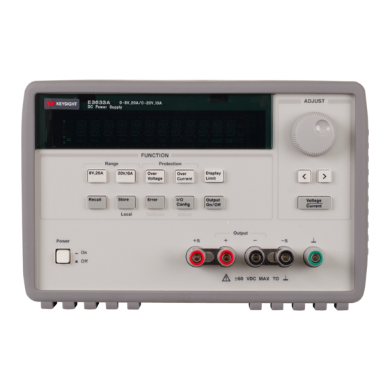
Page 32: Product At A Glance
20V/10A range selection key (E3633A) I/O Configuration key 50V/4A range selection key (E3634A) Output On/Off key Overvoltage protection key Control knob Overcurrent protection key Resolution selection keys Display key limit Voltage/current adjust selection key Recall operating state key Keysight E3633A and E3634A User’s Guide... -
Page 33: Front-Panel Voltage And Current Limit Settings
[2] You can enable the “calibration mode” by holding down this key when you turn on the power supply. [3] You can use it as the “Secure” or “Unsecure” key when the power supply is in the calibration mode. Keysight E3633A and E3634A User’s Guide... - Page 34 All front panel keys and controls can be disabled with remote interface NOTE commands. The Keysight E3633A and Keysight E3634A must be in "Local" mode for the front panel keys and controls to function. Keysight E3633A and E3634A User’s Guide...
-
Page 35: Display Annunciators
Power supply is addressed to listen or talk over a remote interface. Power supply is in remote interface mode. Shows the 8V/20A range is selected. (Keysight E3633A model) Shows the 20V/10A range is selected. (Keysight E3633A model) Shows the 25V/7A range is selected. (Keysight E3634A model) Shows the 50V/4A range is selected. -
Page 36: The Rear Panel At A Glance
Use the front-panel key to: – Select the GPIB or RS-232 interface (see chapter 3). – Set the GPIB bus address (see chapter 3). – Set the RS-232 baud rate and parity (see chapter 3). Keysight E3633A and E3634A User’s Guide... -
Page 37: Input Power Requirements
The power supply is shipped from the factory with a power-line cord that has a plug appropriate for your location. Contact the nearest Keysight Sales and Service Office if the wrong power-line cord is included with your power supply. Your power supply is equipped with a 3-wire grounding type power cord;... - Page 38 3 Rotate the power-line vol tage selector until the correct 4 Replace the power-line vol tage selector and the voltage appears. fuse-holder assembly in the rear panel. Keysight E3633A and E3634A User’s Guide...
- Page 39 Keysight E3633A and E3634A DC Power Supplies User’s Guide Initial Operation Preliminary Checkout Power-on Checkout Output Checkout There are three basic tests in this chapter. The automatic power-on test includes a self-test that checks the internal microprocessors and allows the user visually to check the display.
-
Page 40: Initial Operation
37 if you need to change the power-line voltage or the power-line fuse. To replace the 6.3 AT fuse, order Keysight part number 2110-1030. To replace the 3.15 AT fuse, order Keysight part number 2110-1031. Keysight E3633A and E3634A User’s Guide... -
Page 41: Power-On Checkout
(the 8V or 25V annunciator turns on); and the knob is selected for voltage control. Notice that the OVP and OCP annunciator also turn on. [1] For Keysight E3633A Model [2] For Keysight E3634A Model Keysight E3633A and E3634A User’s Guide... - Page 42 If the power supply detects an error during power-on self-test, the ERROR NOTE annunciator will turn on. See “Error Messages” on page 156 [1] For Keysight E3633A Model [2] For Keysight E3634A Model Keysight E3633A and E3634A User’s Guide...
-
Page 43: Output Checkout
4 Ensure that the voltage can be ad justed from zero to the full rated value. Adjust the knob until the voltmeter indicates 0 volts and then adjust the knob until the voltmeter indicates “8.0 volts” or “25.0 volts” [1] For Keysight E3633A Model [2] For Keysight E3634A Model Keysight E3633A and E3634A User’s Guide... - Page 44 Initial Operation You can use the resolution selection keys to move the blinking digit to the right NOTE or left when setting the voltage. Keysight E3633A and E3634A User’s Guide...
-
Page 45: Current Output Checkout
Adjust the voltage limit to 1.0 volt to assure CC operation. The CC annunciator will turn on. To go back to normal mode, press the key again or let the display time out for several seconds. [1] For Keysight E3633A Model [2] For Keysight E3634A Model Keysight E3633A and E3634A User’s Guide... - Page 46 If an error has been detected during the output checkout procedures, the ERROR NOTE annunciator will turn on. See “Error Messages” on page 156. [1] For Keysight E3633A Model [2] For Keysight E3634A Model Keysight E3633A and E3634A User’s Guide...
- Page 47 Keysight E3633A and E3634A DC Power Supplies User’s Guide Front-Panel Operation Front-Panel Operation Overview Constant Voltage Operation Constant Current Operation Storing and Recalling Operating States Programming Overvoltage Protection Programming Overcurrent Protection Remote Voltage Sensing at the Front and Rear Terminals...
-
Page 48: Front-Panel Operation
The desired output range is selected from the front panel or over the remote interfaces. The 8V or 20V for the E3633A and 25V or 50V for the E3634A annunciator indicates the presently selected range. - Page 49 HPIB interface, the Adrs annunciator will turn on. See “Display annunciators” on page 35 for more information. [1] For Keysight E3633A Model [2] For Keysight E3634A Model Keysight E3633A and E3634A User’s Guide...
-
Page 50: Constant Voltage Operation
We recommend that you should set the display to “limit” mode to see the change of current limit value in the constant voltage mode whenever adjusting the knob. [1] For Keysight E3633A Model [2] For Keysight E3634A Model Keysight E3633A and E3634A User’s Guide... - Page 51 OVP and OCP annunciators. You can use the resolution selection keys to move the blinking digit to the right NOTE or left when setting voltage. [1] For Keysight E3633A Model [2] For Keysight E3634A Model Keysight E3633A and E3634A User’s Guide...
- Page 52 Set the current CURRent {<current>|MIN|MAX} Set the voltage VOLTage {<voltage>|MIN|MAX} Enable the output OUTput ON You can use the resolution selection keys to move the blinking digit to the right NOTE or left when setting voltage. Keysight E3633A and E3634A User’s Guide...
-
Page 53: Constant Current Operation
We recommend that you should set the display to “limit” mode to see the change of voltage limit value in the constant current mode whenever adjusting the knob. [1] For Keysight E3633A Model [2] For Keysight E3634A Model Keysight E3633A and E3634A User’s Guide... - Page 54 OVP and OCP annunciators. You can use the resolution selection keys to move the blinking digit to the right NOTE or left when setting the voltage. [1] For Keysight E3633A Model [2] For Keysight E3634A Model Keysight E3633A and E3634A User’s Guide...
- Page 55 Set the current CURRent {<current>|MIN|MAX} Set the voltage VOLTage {<voltage>|MIN|MAX} Enable the output OUTput ON You can use the resolution selection keys to move the blinking digit to the right NOTE or left when setting voltage. Keysight E3633A and E3634A User’s Guide...
-
Page 56: Storing And Recalling Operating States
To cancel the store operation, let the display time-out after about 3 seconds or press any other function key except the ion key except the key. The power supply returns to the normal operating mode and to the function pressed. Save the operating state. Keysight E3633A and E3634A User’s Guide... - Page 57 This message appears on the display for approximately 1 second. – Remote interface operation: Store an operating state to a specified location *SAL {1|2|3} Recall a previously stored state from a specified location *RCL {1|2|3} Keysight E3633A and E3634A User’s Guide...
-
Page 58: Programming Overvoltage Protection
You will see the above message on the display when you enter the OVP menu. Adjust the control knob for the desired OVP trip level. Note that you cannot set the trip levels to lower than 1.0 volt. [1] For Keysight E3633A Model [2] For Keysight E3634A Model Keysight E3633A and E3634A User’s Guide... - Page 59 The following steps show how to clear the overvoltage condition and get back to normal mode operation. In the following steps, the display will go back to “OVP TRIPPED” if you let the display time out after about several seconds. Keysight E3633A and E3634A User’s Guide...
- Page 60 3 Clear the overvoltage cond ition and exit this menu. Now, when you press key again, the “DONE” message is displayed for a second and the OVP annunciator will not blink any more. The output will return to meter mode. Keysight E3633A and E3634A User’s Guide...
- Page 61 SCR will continuously sink a large current from the source; possibly damaging the power supply. To avoid this a diode must be connected in series with the output as shown in Figure 3-1 next page. Keysight E3633A and E3634A User’s Guide...
-
Page 62: For Battery Charging
Front-Panel Operation Figure 3-1 Recommended protection circuit for battery charging Keysight E3633A and E3634A User’s Guide... -
Page 63: Programming Overcurrent Protection
You will see the above message on the display when you enter the OCP menu. Adjust the knob for the desired OCP trip level. [1] For Keysight E3633A Model [2] For Keysight E3634A Model Keysight E3633A and E3634A User’s Guide... - Page 64 The following steps show how to clear the overcurrent condition and get back to normal mode operation. In the following steps, the display will go back to “OCP TRIPPED” if you let the display time out after about several seconds. Keysight E3633A and E3634A User’s Guide...
- Page 65 OCP annunciator will not blink any more. The output will return to meter mode. The knob is selected for current control. Notice that the power supply is operated in the constant current (CC) mode. Keysight E3633A and E3634A User’s Guide...
- Page 66 OCP annunciator will not blink any more. The output will return the meter mode. – Remote interface operation: Set the OCP level CURR:PROT {<current>|MIN|MAX} Disable or enable the OCP circuit CURR:PROT:STAT {OFF|ON} Clear the tripped OCP circuit CURR:PROT:CLE Keysight E3633A and E3634A User’s Guide...
-
Page 67: Remote Voltage Sensing At The Front And Rear Terminals
The performance specifications are not guaranteed when the maximum output voltage is exceeded. If the excessive demand on the power supply forces the power supply to lose regulation, the Unreg annunciator will turn on to indicate that the output is unregulated. Keysight E3633A and E3634A User’s Guide... -
Page 68: Output Noise
Observe polarity when connecting the sensing leads to the load. For local voltage sensing connections, the (+) and (-) sense terminals must be connected to the (+) and (-) output terminals respectively. Keysight E3633A and E3634A User’s Guide... - Page 69 During remote sensing setup, it is strongly recommended to power off (by NOTE pressing power ON/OFF button) the power supply to avoid undesirable damage to the load or the power supply. Figure 3-2 Remote voltage sensing connections Keysight E3633A and E3634A User’s Guide...
-
Page 70: Remote Voltage Sensing At The Rear Panel
Figure 3-3 Rear local sensing connections For rear local voltage sensing connections, the front shorting bars must be NOTE removed first and connect the sense wires as shown in Figure 3-3. Keysight E3633A and E3634A User’s Guide... -
Page 71: Disabling The Output
– Front-panel operation: You can disable the output by pressing key. This key toggles between output “Off” and “On” states. – Remote interface operation: Disable or enable the output OUTP {OFF|ON} Keysight E3633A and E3634A User’s Guide... -
Page 72: Disabling The Output Using An External Relay
See the Service Guide for more information. – Do not use the RS-232 interface if you have configured the power supply to output relay control signals. Internal components on the RS-232 circuitry may be damaged. Keysight E3633A and E3634A User’s Guide... -
Page 73: Knob Locking
Notice that the knob and front panel keys are disabled when in the remote interface mode. Keysight E3633A and E3634A User’s Guide... -
Page 74: System-Related Operations
The self-test will begin when you release the key following the beep. – Remote interface operation: *TST? Returns “0” if the complete self-test passes or “1” if it fails. Keysight E3633A and E3634A User’s Guide... -
Page 75: Error Conditions
+0, “No error” over the remote interface or “NO ERRORS” from the front panel. – The error queue is cleared when power has been off or after a *CLS (clear status) command has been executed. The *RST (reset) command does not clear the error queue. Keysight E3633A and E3634A User’s Guide... - Page 76 30 seconds. – Remote interface operation: Read and clear one error from the error queue SYSTem:ERRor? Errors have the following format (the error string may contain up to 80 characters). -102, “Syntax error” Keysight E3633A and E3634A User’s Guide...
-
Page 77: Display Control
DISP {OFF|ON} Display the strong enclosed in quotes DISP:TEXT <quoted string> Clear the displayed message DISP:TEXT:CLE The following statement shows how to display a message on the front panel from a Hewlett-Packard controller. “DISP:TEXT ‘HELLO’” Keysight E3633A and E3634A User’s Guide... -
Page 78: Firmware Revision Query
Query the SCPI version SYST:VERS? Returns a string in the form “YYYY.V” where the “Y’s” represent the year of the version, and the “V” represents a version number for that year (for example, 1996.0). Keysight E3633A and E3634A User’s Guide... -
Page 79: Remote Interface Configuration
84 for more information on connecting the power supply to a computer over the HPIB interface. [2] Refer to “RS-232 Interface Configuration” on page 85 for more information on connecting the power supply to a computer over the RS-232 interface. Keysight E3633A and E3634A User’s Guide... -
Page 80: Hpib Address
Odd (7 data bits). When you set the parity, you are indirectly setting the number of data bits. – The parity selection is stored in non-volatile memory, and does not change when power has been off or after a remote interface reset. Keysight E3633A and E3634A User’s Guide... -
Page 81: To Set The Hpib Address
If the HPIB address is not changed, “NO CHANGE” will be displayed for one second. To exit the I/O configuration mode without any further changes, press the “I/O NOTE Config” key until the “NO CHANGE” message is displayed. Keysight E3633A and E3634A User’s Guide... -
Page 82: To Set The Baud Rate And Parity (Rs-232)
Choose from one of the following by turning the knob to the right or left: None 8 Bits, Odd 7 Bits, or Even 7 Bits. When you set parity, you are indirectly setting the number of the data bits. Keysight E3633A and E3634A User’s Guide... - Page 83 If the baud rate and the parity are not changed, “NO CHANGE” will be displayed for one second. To exit the I/O configuration mode without any further changes, press the “I/O NOTE Config” key until the “NO CHANGE” message is displayed. Keysight E3633A and E3634A User’s Guide...
-
Page 84: Hpib Interface Configuration
NOTE exceed 4 meters. Do not stack more than three connector blocks together on any HPIB connector. Make sure that all connectors are fully seated and that the lock screws are firmly finger tightened. Keysight E3633A and E3634A User’s Guide... -
Page 85: Rs-232 Interface Configuration
The frame is defined as the characters from the start bit to the last stop bit, inclusively. Within the frame, you can select the baud rate, number of data bits, and parity type. The power supply uses the following frame formats for seven and eight data bits. Keysight E3633A and E3634A User’s Guide... -
Page 86: Connection To A Computer Or Terminal
If your configuration is different than those described, order the HP 34399A Adapter Kit. This kit contains adapters for connection to other computers, terminals, and modems. Instructions and pin diagrams are included with the adapter kit. Keysight E3633A and E3634A User’s Guide... - Page 87 If your computer or terminal has a 25-pin serial port with a male connector, use the null-modem cable and 25-pin adapter included with the HP 34398A Cable Kit. The cable and adapter pin diagram are shown below. Keysight E3633A and E3634A User’s Guide...
-
Page 88: Dtr / Dsr Handshake Protocol
(this is equivalent to the IEEE-488 device clear action). For the <Ctrl-C> character to be recognized reliably by the power supply while it holds DTR FALSE, the bus controller must first set DSR FALSE. Keysight E3633A and E3634A User’s Guide... -
Page 89: Rs-232 Troubleshooting
The HP 34398A Cable Kit can be used to connect the power supply to most computers or terminals. – Verify that you have connected the interface cable to the correct serial port on your computer (COM1, COM2, etc). Keysight E3633A and E3634A User’s Guide... -
Page 90: Calibration Overview
To unsecure the power supply from the front panel, omit the “H P” and enter the remaining numbers as shown on the following pages. H P _ _ _ _ _ _ (8 characters) [1] For Keysight E3633A Model [2] For Keysight E3634A Model Keysight E3633A and E3634A User’s Guide... - Page 91 If you forget your security code, you can disable the security feature by adding a NOTE jumper inside the power supply, and then entering a new code. See the Service Guide for more information. Keysight E3633A and E3634A User’s Guide...
- Page 92 Notice that if the security is incorrect, the power supply displays an “INVALID” message for a second and returns to the code entering mode for you to enter the correct code. [1] For Keysight E3633A Model [2] For Keysight E3634A Model Keysight E3633A and E3634A User’s Guide...
- Page 93 Secure or unsecure the power supply CAL:SEC:STAT {OFF|ON},<code> To unsecure the power supply, send the above command with the same code used to secure. For example, (E3633A) “CAL:SEC:STAT OFF, HP003633” (E3634A) “CAL:SEC:STAT OFF, HP003634” Keysight E3633A and E3634A User’s Guide...
- Page 94 To exit the calibration mode, turn the power off and on. SECURED [1] For Keysight E3633A Model [2] For Keysight E3634A Model Keysight E3633A and E3634A User’s Guide...
- Page 95 Secure or unsecure the power supply CAL:SEC:STAT {OFF|ON},<code> To secure the power supply, send the above command with the same code as used to unsecure. For example, (E3633A) “CAL:SEC:STAT ON, HP003633” (E3634A) “CAL:SEC:STAT ON, HP003634” Keysight E3633A and E3634A User’s Guide...
- Page 96 Then, enter the new code. For example, Unsecure with old code “CAL:SEC:STAT OFF, HP003633 or HP003634 ” Enter new code “CAL:SEC:CODE ZZ001443” Secure with new code “CAL:SEC:STAT ON, ZZ001443” [a] For Keysight E3633A Model [b] For Keysight E3634A Model Keysight E3633A and E3634A User’s Guide...
-
Page 97: Calibration Count
0. Since the value increments by one for each calibration point, a complete calibration will increase the value by 5 counts. – Remote interface operation: Query the number of times of calibration CAL:COUN? Keysight E3633A and E3634A User’s Guide... -
Page 98: Calibration Message
– Remote interface operation: Store the cal message CAL:STR <quoted string> The following command strong shows how to store a calibration message. “CAL:STR ‘CAL 12-05-98’” Keysight E3633A and E3634A User’s Guide... - Page 99 Keysight E3633A and E3634A DC Power Supplies User’s Guide Remote Interface Reference SCPI Command Summary Simplified Programming Overview Using the APPLy Command Output Setting and Operation Commands Triggering Commands System-Related Commands Calibration Commands RS-232 Interface Commands The SCPI Status Registers...
-
Page 100: Remote Interface Reference
– Triangle brackets (< >) indicate that you must substitute a value or a code for the enclosed parameter. – A vertical bar ( | ) separates one of two or more alternative parameters. First-time SCPI users, see page 143. Keysight E3633A and E3634A User’s Guide... - Page 101 CURRent[:LEVel]:TRIGgered[:AMPLitude] {<current>|MIN|MAX} CURRent[:LEVel]:TRIGgered[:AMPLitude]? [MIN|MAX] CURRent:PROTection[:LEVel] {<current>|MIN|MAX} CURRent:PROTection[:LEVel]? {MIN|MAX} CURRent:PROTection:STATe {0|1|OFF|ON} CURRent:PROTection:STATe? CURRent:PROTection:TRIPped? CURRent:PROTection:CLEar VOLTage[:LEVel][:IMMediate][:AMPLitude] {<voltage>|MIN|MAX|UP|DOWN} VOLTage[:LEVel][:IMMediate][:AMPLitude]? [MIN|MAX] VOLTage[:LEVel][:IMMediate]:STEP[:INCRement] {<numeric value>|DEFault} VOLTage[:LEVel][:IMMediate]:STEP[:INCRement]? {DEFault} VOLTage[:LEVel]:TRIGgered[:AMPLitude] {<voltage>|MIN|MAX} VOLTage[:LEVel]:TRIGgered[:AMPLitude]? [MIN|MAX] VOLTage:PROTection[:LEVel] {<voltage>|MIN|MAX} VOLTage:PROTection[:LEVel]? {MIN|MAX} VOLTage:PROTection:STATe {0|1|OFF|ON} VOLTage:PROTection:STATe? VOLTage:PROTection:TRIPped? VOLTage:PROTection:CLEar Keysight E3633A and E3634A User’s Guide...
- Page 102 Remote Interface Reference VOLTage:RANGe {P8V |P20V |P25V |P50V |LOW|HIGH} VOLTage:RANGe? MEASure :CURRent[:DC]? [:VOLTage][:DC]? Triggering Commands INITiate[:IMMediate] TRIGger[:SEQuence] :DELay {<seconds>|MIN|MAX} :DELay? :SOURce {BUS|IMM} :SOURce? *TRG [1] For Keysight E3633A Model [2] For Keysight E3634A Model Keysight E3633A and E3634A User’s Guide...
- Page 103 Remote Interface Reference System-Related Commands DISPlay[:WINDow] [:STATe] {OFF|ON} [:STATe]? :TEXT[:DATA] <quoted string> :TEXT[:DATA]? :TEXT:CLEar SYSTem :BEEPer[:IMMediate] :ERRor? :VERSion? OUTPut :RELay[:STATe] {OFF|ON} :RELay[:STATe]? [:STATe] {OFF|ON} [:STATe]? *IDN? *RST *TST? *SAV {1|2|3} *RCL {1|2|3} Keysight E3633A and E3634A User’s Guide...
- Page 104 Remote Interface Reference Calibration Commands CALibration :COUNt? :CURRent[:DATA] <numeric value> :CURRent:LEVel {MIN|MID|MAX} :CURRent:PROTection :DAC:ERRor :SECure:CODE <new code> :SECure:STATe {OFF|ON},<code> :SECure:STATe? :STRing <quoted string> :STRing? :VOLTage[:DATA] <numeric value> :VOLTage:LEVel {MIN|MID|MAX} :VOLTage:PROTection Keysight E3633A and E3634A User’s Guide...
- Page 105 Status Reporting Commands STATus:QUEStionable :CONDition? [:EVENt]? :ENABle <enable value> :ENABle? SYSTem:ERRor? *CLS *ESE <enable value> *ESE? *ESR? *OPC *OPC? *PSC {0|1} *PSC? *SRE <enable value> *SRE? *STB? *WAI RS-232 Interface Commands SYSTem :LOCal :REMote :RWLock Keysight E3633A and E3634A User’s Guide...
- Page 106 Remote Interface Reference IEEE-488.2 Common Commands *CLS *ESR? *ESE <enable value> *ESE? *IDN? *OPC *OPC? *PSC {0|1} *PSC? *RST *SAV {1|2|3} *RCL {1|2|3} *STB? *SRE <enable value> *SRE? *TRG *TST? *WAI Keysight E3633A and E3634A User’s Guide...
-
Page 107: Simplified Programming Overview
3 V rated at 1 A: Set output voltage to 3.0 V “VOLT 3.0” Set output current to 1.0 A “CURR 1.0” Keysight E3633A and E3634A User’s Guide... -
Page 108: Reading A Query Response
Set the triggered voltage level to 3.0 V “VOLT:TRIG 3.0” Set the triggered current level to 1.0 A “CURR:TRIG 1.0” Select the immediate trigger as a source “TRIG:SOUR IMM” Cause the trigger system to initiate “INIT” Keysight E3633A and E3634A User’s Guide... -
Page 109: Power Supply Programming Ranges
The available SOURce programming value for a parameter varies according to the desired output range of the power supply. The following table lists the programming values available and reset values of the Keysight E3633A and MINimum MAXimum DEFault E3634A power supplies. -
Page 110: Keysight E3634A Programming Ranges
*RST Value Current Programming Range 0 A to 7.21 A 0 A to 4.12 A MAX Value 7.21 A 4.12 A MIN Value DEFaul t Value 7.0 A 4.0 A *RST Value 7.00 A Keysight E3633A and E3634A User’s Guide... -
Page 111: Using The Apply Command
The default values of voltage and current are “0” volts and “20” or “7” amps regardless of the presently selected range. For more details of parameters, see Table 4-1 for the Keysight E3633A model and Table 4-2 for the Keysight E3634A model. If you specify only one parameter of the... - Page 112 “8.00000,20.00000” or “25.00000,7.00000” [a] Keysight E3633A Model [b] Keysight E3634A Model In the above string, the first number 8.00000 is the voltage setting value and the second number 20.00000 is the current setting value. Keysight E3633A and E3634A User’s Guide...
-
Page 113: Output Setting And Operation Commands
CURR:STEP command. Set the step size to 0.01 A “CURR:STEP 0.01” Increase the output current “CURR UP” Set the step size to 0.02 A “CURR:STEP 0.02” Decrease the output current “CURR DOWN” Keysight E3633A and E3634A User’s Guide... - Page 114 CURRent DOWN To set the step size to the minimum resolution, set the step size to “DEFault” The minimum resolution of the step size is approximately 0.32 mA (E3633A) and 0.13 mA (E3634A) respectively. The returns the minimum CURR:STEP? DEF resolution of your instrument.
- Page 115 OCP point, or raise the OCP trip level above the output setting. Note that the overcurrent condition caused by an external source must be removed first before proceeding this command. Keysight E3633A and E3634A User’s Guide...
- Page 116 Decrease the output voltage “VOLT DOWN” VOLTage? [MINimum|MAXimum] This query returns the presently programmed voltage level of the power supply. return the highest and lowest VOLT? MAX VOLT? MIN programmable voltage levels for the selected range. Keysight E3633A and E3634A User’s Guide...
- Page 117 VOLT DOWN To set the step size to the minimum resolution, set the step size to “DEFault”. The minimum resolution of the step size is approximately 0.36 mV (E3633A) and 0.95 mV (E3634A) respectively. The returns the minimum VOLT:STEP? DEF resolution of your instrument.
- Page 118 OVP point, or raise the OVP trip level above the output setting. Note that the overvoltage condition caused by an external source must be removed first before proceeding this command. Keysight E3633A and E3634A User’s Guide...
- Page 119 *RST VOLTage:RANGe? This query returns the currently selected range. The returned parameter for the Keysight E3633A is “P20V” (HIGH) or “P8V” (LOW) and the parameter for the Keysight E3634A is “P50V” (HIGH) or “P25V” (LOW). MEASure:CURRent? This command queries the current measured across the current sense resistor inside the power supply.
-
Page 120: Triggering Commands
– You can also trigger the power supply from the GPIB interface by sending the IEEE-488 Group Execute Trigger (GET) message. The following statement shows how to send a GET from a Keysight Technologies controller. (group execute trigger) TRIGGER 705... - Page 121 – To select the immediate trigger source, send the following command. TRIG:SOUR IMM – When the is selected as a trigger source, an command IMMediate INITiate immediately transfers the value to value. VOLT:TRIG CURR:TRIG VOLT CURR Any delay is ignored. Keysight E3633A and E3634A User’s Guide...
-
Page 122: Triggering Commands
). The command has the TRIG:SOUR BUS same effect as the Group Execute Trigger (GET) command. For RS-232 operation, make sure the power supply is in the remote interface mode by sending the command first. SYST:REM Keysight E3633A and E3634A User’s Guide... -
Page 123: System-Related Commands
0 V and the current value is 20 mA. At , the output state is OFF. *RST OUTPut? This command queries the output state of the power supply. The returned value is “0” (OFF) or “1” (ON). Keysight E3633A and E3634A User’s Guide... - Page 124 Internal components on the RS-232 circuitry may be damaged. OUTPut:RELay? This command returns the state of the TTL relay logic signals. See also command. OUTP:REL SYSTem:BEEPer This command issues a single beep immediately. Keysight E3633A and E3634A User’s Guide...
- Page 125 The command returns a string with the following format (be sure to dimension a string variable with at least 40 characters): HEWLETT-PACKARD,E3633A or E3634A,0,X.X-X.X-X.X Keysight E3633A and E3634A User’s Guide...
- Page 126 CURR: PROT 22.0 A 7.5 A CURR:PROT:STAT DISP OUTP OUTP:REL TRIG:DEL TRIG:SOUR VOLT VOLT:STEP 0.36 mV (typical value) 0.95 mV (typical value) VOLT:TRIG VOLT:PROT 22.0 V 55.0 V VOLT:PROT:STAT VOLT:RANG P8V (Low) P25V (Low) Keysight E3633A and E3634A User’s Guide...
- Page 127 Going DISP {OFF|ON} NOTE to local mode automatically sets the display state to ON. Keysight E3633A and E3634A User’s Guide...
-
Page 128: Calibration Commands
ON. It sets the power supply to a calibration point that is entered with command. During calibration, three points must be entered and the CAL:CURR low-end point (MIN) must be selected and entered first. Keysight E3633A and E3634A User’s Guide... - Page 129 The calibration message may contain up to 40 characters. The power supply should be unsecured before sending a calibration message. CALibration:STRing? This command queries the calibration message and returns a quoted string. Keysight E3633A and E3634A User’s Guide...
- Page 130 The power supply automatically performs the calibration and stores the new overvoltage constant in nonvolatile memory. Notice that voltage calibration precedes before sending this command. Keysight E3633A and E3634A User’s Guide...
-
Page 131: Rs-232 Interface Commands
“Local” key. Ctrl-C This command clears the operation in progress over the RS-232 interface and discards any pending output data. This is equivalent to the IEEE-488 device clear action over the GPIB interface. Keysight E3633A and E3634A User’s Guide... -
Page 132: The Scpi Status Registers
To enable bits in an enable register, you must write a decimal value which corresponds to the binary-weighted sum of the bits you wish to enable in the register. Keysight E3633A and E3634A User’s Guide... -
Page 133: Scpi Status System
Remote Interface Reference SCPI Status System Keysight E3633A and E3634A User’s Guide... -
Page 134: The Questionable Status Register
For example, 16 is returned when you have queried the status of the questionable event register, the temperature condition is questionable. The questionable status enable register is cleared when: – You execute command. STAT:QUES:ENAB 0 Keysight E3633A and E3634A User’s Guide... -
Page 135: The Standard Event Register
Command Error. A command syntax error occurred (see error numbers -101 through -178 in chapter 5). Not Used 0 Always set to 0. Power On. Power has been turned off and on since the last time the event register was read or cleared. Keysight E3633A and E3634A User’s Guide... -
Page 136: The Status Byte Register
Data is available in the power supply output buffer. One or more bits are set in the standard event register (bits must be “enabled” in the enable register). The power supply is requesting service (serial poll). Not Used Always set to 0. Keysight E3633A and E3634A User’s Guide... -
Page 137: Using Service Request (Srq) And Serial Poll
Serial poll will automatically clear the “request service” bit in the Status Byte summary register. No other bits are affected. Performing a serial poll will not affect instrument throughput. Keysight E3633A and E3634A User’s Guide... -
Page 138: Using *Stb? To Read The Status Byte
Standard Event register and the command for the Status Byte. *SRE 4 Send the (operation complete query) command and enter the result to *OPC? ensure synchronization. 5 Enable your bus controller’s IEEE-488 SRQ interrupt. Keysight E3633A and E3634A User’s Guide... -
Page 139: To Determine When A Command Sequence Is Completed
“operation complete” bit to determine when the message is available. However, if too many messages are generated before the *OPC command executes (sequentially), the output buffer will fill and the power supply will stop processing commands. Keysight E3633A and E3634A User’s Guide... -
Page 140: Status Reporting Commands
If “1” is returned, the power supply is in the CC operating mode and if “2” is returned, the power supply is in the CV operating mode. If “3” is returned, the power supply is in failure. Keysight E3633A and E3634A User’s Guide... - Page 141 *OPC This command sets the “Operation Complete” bit (bit 0) of the Standard Event register after the command is executed. Keysight E3633A and E3634A User’s Guide...
- Page 142 Service” bit (bit 6) is not cleared if a serial poll has occurred. *WAI This command instructs the power supply to wait for all pending operations to complete before executing any additional commands over the interface. Used only in the triggered mode. Keysight E3633A and E3634A User’s Guide...
-
Page 143: An Introduction To The Scpi Language
VOLTage? [MIN|MAX] VOLTage: TRIGgered {<voltage>|MIN|MAX} TRIGgered? {MIN|MAX} is the root keyword of the command, SOURce CURRent VOLTage second-level keywords, and is third-level keywords. A colon (:) TRIGgered separates a command keyword from a lower-level keyword. Keysight E3633A and E3634A User’s Guide... -
Page 144: Command Format Used In This Manual
If a command requires more than one parameter, you must separate adjacent parameter using a comma as shown below: “SOURce:CURRent:TRIGgered” “APPLy 3.5,1.5” Keysight E3633A and E3634A User’s Guide... -
Page 145: Command Separators
For example, consider the following command: CURRent {<current>|MIN|MAX} Instead of selecting a specific current, you can substitute MINimum to set the current to its minimum value or MAXimum to set the current to its maximum value. Keysight E3633A and E3634A User’s Guide... -
Page 146: Querying Parameter Settings
<new line> character. A <carriage return> followed by a <new line> is also accepted. Command string termination will always reset the current SCPI command path to the root level. The <new line> character has the ASCII decimal code of 10. Keysight E3633A and E3634A User’s Guide... -
Page 147: Ieee-488.2 Common Commands
Discrete parameters are used to program settings that have a limited number of values (like ). Query responses will always return the short form in all upper-case letters. The following command uses discrete parameters: TRIG:SOUR {BUS|IMM} Keysight E3633A and E3634A User’s Guide... - Page 148 You can include the quote delimiter as part of the string by typing it twice without any characters in between. The following command uses a string parameter: DISP:TEXT <quoted string> Keysight E3633A and E3634A User’s Guide...
-
Page 149: Halting An Output In Progress
88 for further details. All remote interface configurations can be entered only from the front panel. See NOTE “Remote Interface Configuration” in chapter 3 to configure for GPIB or RS-232 interface before operating the power supply remotely. Keysight E3633A and E3634A User’s Guide... -
Page 150: Scpi Conformance Information
Remote Interface Reference SCPI Conformance Information The Keysight E3633A and E3634A DC Power Supplies conform to the ‘1996.0’ version of the SCPI standard. Many of the commands required by the standard are accepted by the power supply but are not described in this manual for simplicity or clarity. - Page 151 :CURRent:PROTection:TRIPped? :CURRent:PROTection:CLEar [SOURce] :VOLTage[:LEVel][:IMMediate][:AMPLitude] {<voltage>|MIN|MAX|UP|DOWN} :VOLTage[:LEVel][:IMMediate][:AMPLitude]?[MIN|MAX] :VOLTage[:LEVel][:IMMediate]:STEP[:INCRement] {<numeric value>|DEFault} :VOLTage[:LEVel][:IMMediate]:STEP[:INCRement]? {DEFault} :VOLTage[:LEVel]:TRIGgered[:AMPLitude] {<voltage>|MIN|MAX} :VOLTage[:LEVel]:TRIGgered[:AMPLitude]?[MIN|MAX] :VOLTage:PROTection[:LEVel] {<voltage>|MIN|MAX} :VOLTage:PROTection[:LEVel]? {MIN|MAX} :VOLTage:PROTection:STATe {0|1|OFF|ON} :VOLTage:PROTection:STATe? :VOLTage:PROTection:TRIPped? :VOLTage:PROTection:CLEar :VOLTage:RANGe {P8V|P20V|LOW|HIGH} (For E3633A model) :VOLTage:RANGe {P25V|P50V|LOW|HIGH} (For E3634A model) :VOLTage:RANGe? Keysight E3633A and E3634A User’s Guide...
- Page 152 Remote Interface Reference STATus :QUEStionable:CONDition? :QUEStionable[:EVENt]? :QUEStionable:ENABle <enable value> :QUEStionable:ENABle? SYSTem :BEEPer[:IMMediate] :ERRor? :VERSion TRIGger [:SEQuence]:DELay {<seconds>|MIN|MAX} [:SEQuence]:DELay? [:SEQuence]:SOURce{BUS|IMM} [:SEQuence]:SOURce Keysight E3633A and E3634A User’s Guide...
-
Page 153: Non-Scpi Commands
Remote Interface Reference Device specific commands The following commands are device-specific to the Keysight E3633A and Keysight E3634A power supplies. They are not included in the ‘1996.0’ version of the SCPI standard. However, these commands are designed with the SCPI standard in mind and they follow all of the command syntax rules defined by the standard. -
Page 154: Ieee-488 Conformance Information
End or Identify *PSC? Group Execute Trigger *RST Go To Local *SAV {1|2|3} Local Lockout *RCL {1|2|3} Selected Device Clear *SRE <enable value> Serial Poll Disable *SRE? Serial Poll Enable *STB? *TRG *TST? *WAI Keysight E3633A and E3634A User’s Guide... - Page 155 Keysight E3633A and E3634A DC Power Supplies User’s Guide Error Messages Error Messages Execution Errors Self-Test Errors Calibration Errors...
-
Page 156: Error Messages
30 seconds. – Remote interface operation: Read and clear one error from the error queue SYSTem:ERRor? Errors have the following format (the error string may contain up to 80 characters). -102, “Syntax error” Keysight E3633A and E3634A User’s Guide... -
Page 157: Execution Errors
-108 More parameters were received than expected for the command. You may have entered an extra parameter, or you added a parameter to a command that does not accept a parameter. Example: APPL? 10 Keysight E3633A and E3634A User’s Guide... - Page 158 Example: APPL 1.0E+320000 Invalid character in number -121 An invalid character was found in the number specified for a parameter value. Example: *ESE #B01010102 [a] This error message is only applicable for serial MY53xx6xxx. Keysight E3633A and E3634A User’s Guide...
- Page 159 A suffix was received following a numeric parameter which does not accept a suffix. Example: STAT:QUES:ENAB 18 SEC (SEC is not a valid suffix). [a] This error message is only applicable for serial MY53xx6xxx. Keysight E3633A and E3634A User’s Guide...
- Page 160 Example: DISP:TEXT ON Invalid string data -151 An invalid character string was received. Check to see if you have enclosed the character string in single or double quotes. Example: DISP:TEXT ’ON Keysight E3633A and E3634A User’s Guide...
- Page 161 Indicates that a legal program data element was parsed but could not be executed due to the current device state. Data out of range -222 A numeric parameter value is outside the valid range for the command. Example: TRIG:DEL -3 Keysight E3633A and E3634A User’s Guide...
- Page 162 For example, you may have executed an command (which does not APPLy generate data) and then attempted an statement to read data from the ENTER remote interface. Keysight E3633A and E3634A User’s Guide...
- Page 163 Command allowed only with RS-232 There are three commands which are only allowed with the RS-232 interface: , and SYSTem:LOCal SYSTem:REMote SYSTem:RWLock Input buffer overflow Output buffer overflow [a] This error message is only applicable for serial MY53xx6xxx. Keysight E3633A and E3634A User’s Guide...
- Page 164 Error Messages Command not allowed in local You should always execute the command before sending other SYSTem:REMote commands over the RS-232 interface. Keysight E3633A and E3634A User’s Guide...
-
Page 165: Self-Test Errors
Serial configuration readback failed System ADC test failed Unable to sense line frequency I/O processor does not respond I/O processor failed self-test Fan test failed [a] This error message is only applicable for serial MY53xx6xxx. Keysight E3633A and E3634A User’s Guide... - Page 166 Error Messages System DAC test failed Hardware test failed Keysight E3633A and E3634A User’s Guide...
-
Page 167: Calibration Errors
A calibration in progress is aborted when you press any front-panel key, send a device clear, or change the local/remote state of the instrument. Cal output disabled Calibration is aborted by sending command during calibrating a OUTP OFF output. Keysight E3633A and E3634A User’s Guide... - Page 168 OFF before and during the calibration. Gain out of range for Gain Error Correction The slope of the DAC gain is out of range. Hardware fails. Cal checksum failed, secure state Keysight E3633A and E3634A User’s Guide...
- Page 169 Cal checksum failed, store/recall data in location 3 Cal checksum failed, DAC cal constants Cal checksum failed, readback cal constants Cal checksum failed, GPIB address Cal checksum failed, internal data Cal checksum failed, DAC DNL error correction data Keysight E3633A and E3634A User’s Guide...
- Page 170 Error Messages THIS PAGE HAS BEEN INTENTIONALLY LEFT BLANK. Keysight E3633A and E3634A User’s Guide...
-
Page 171: Application Programs
Keysight E3633A and E3634A DC Power Supplies User’s Guide Application Programs Example Program for C and C++ Example Program for Excel 97 This chapter contains two application programs over the remote interface to help you develop programs for your own application. Chapter 4, “Remote Interface... -
Page 172: Example Program For C And C
= 1; /* Set the number to 0 for use with the RS-232 */ long ErrorStatus; /* VISA Error code */ char commandString[256]; char ReadBuffer[256]; void delay(clock_t wait); void SendSCPI(char* pString); void CheckError(char* pMessage); void OpenPort(); Continued on the next page Keysight E3633A and E3634A User’s Guide... - Page 173 /* Build the address required to open communication with GPIB card or RS-232.*/ /* The address format looks like this: "GPIB0::5::INSTR". /* To use the RS-232 interface using COM1 port, change it to "ASRL1::INSTR" /* address format Continued on next page Keysight E3633A and E3634A User’s Guide...
- Page 174 /* For use with COM2 port, use "ASRL2::INSTR" address format * strcpy(VISA_address,"ASRL"); strcat(VISA_address,COM_Address); strcat(VISA_address,"::INSTR"); /* Open communication session with the power supply */ ErrorStatus = viOpenDefaultRM(&defaultRM); ErrorStatus = viOpen(defaultRM,VISA_address,0,0,&power_supply); CheckError("Unable to open port"); if(!bGPIB) SendSCPI("System:Remote"); Continued on next page Keysight E3633A and E3634A User’s Guide...
- Page 175 /* Close the communication port */ viClose(power_supply); viClose(defaultRM); void CheckError(char* pMessage) if (ErrorStatus VI_SUCCESS) printf("\n %s",pMessage); ClosePort(); exit(0); void delay(clock_t wait) clock_t goal; goal = wait + clock(); while( goal > clock() ) ; End of program Keysight E3633A and E3634A User’s Guide...
-
Page 176: Example Program For Excel 97
This section contains the example program written using Excel Macros (Visual Basic® for Applications) to control your Keysight E3633A or Keysight E3634A. With Excel you can take the value of a cell in a spread sheet, send it to the power supply, and then record the response on the worksheet. - Page 177 PC to get the GPIB port or RS-232 port to work properly. To use the example with Window® 3.1, you will need to modify the declarations NOTE at the top of the module. Change ‘visa32.dll’ to ‘visa.dll’ in all declarations. Keysight E3633A and E3634A User’s Guide...
-
Page 178: Diode Macro
ErrorStatus = viOpen(defaultRM, "GPIB0::" & GPIB_Address & "::INSTR", _0, 1000, power_supply) Else ErrorStatus = viOpen(defaultRM, "ASRL" & COM_Address & "::INSTR", _0, 1000, power_supply) SendSCPI "System:Remote" End If CheckError "Unable to open port" End Function Continued on next page Keysight E3633A and E3634A User’s Guide... - Page 179 Finish = Timer + delay_time Loop Until Finish <= Timer End Function Private Function CheckError(ErrorMessage As String) If ErrorStatus < VI_SUCCESS Then Cells(5, 2) = ErrorMessage ClosePort End If End Function End of program Keysight E3633A and E3634A User’s Guide...
-
Page 180: Declaration For Windows 3.1
' uses the VTL Library to send commands to an instrument. A description of these ' and additional VTL commands are contained in the Hewlett Packard Visa ' Transition Library book Keysight Part Number E2094-90002. '***************************************************************************** Declare Function viOpenDefaultRM Lib "VISA.DLL" Alias "#141" (viDefaultRM As Long) As Long Declare Function viOpen Lib "VISA.DLL"... -
Page 181: Tutorial
This chapter describes basic operation of linear power supplies and gives specific details on the operation and use of the Keysight E3633A and Keysight E3634A DC power supplies:... -
Page 182: Overview Of Keysight E3633A And Keysight E3634A Operation
Tutorial Overview of Keysight E3633A and Keysight E3634A Operation The basic design technique, which has not changed over the years, consists of placing a control element in series with the rectifier and load device. Figure 7-1 shows a simplified schematic of a series regulated supply with the phase-controlled pre-regulator described as a power switch and the series element depicted as a variable resistor. -
Page 183: Figure 7-2 Block Diagram Of The Power Supply Showing The Isolation
The Keysight E3633A and Keysight E3634A contain a linear regulated power supply. It is controlled by a control circuit that provides voltages to program the outputs. -
Page 184: Output Characteristics
The output of the E3633A and E3634A power supplies can operate in either constant voltage (CV) mode or constant-current (CC) mode. Under certain fault conditions, the power supply cannot operate in either CV or CC mode and becomes unregulated. -
Page 185: Figure 7-5 Output Characteristics
Tutorial Figure 7-5 shows the operating modes of the output of the Keysight E3633A and Keysight E3634A power supplies. The operating point of one supply will be either above or below the line R . This line represents a load where the output voltage and the output current are equal to the voltage and current setting. -
Page 186: Unregulated State
Normal mode voltage noise is in the form of ripple related to the line frequency plus some random noise. Both of these are of very low value in the Keysight E3633A and Keysight E3634A. Careful lead layout and keeping the power supply circuitry away from power devices and other noise sources will keep these values low. - Page 187 When very rapid changes in load are expected, a capacitor with a low series resistance, in parallel with the power supply, and close to the load is the best way to minimize these voltage spikes. Keysight E3633A and E3634A User’s Guide...
-
Page 188: Connecting The Load
Suggested maximum Current (amps) mΩ/ft 1.00 1.59 2.53 4.02 6.39 10.2 16.1 25.7 40.8 64.9 mΩ/ft 13.2 21.0 33.5 52.8 84.3 133.9 212.9 [a] Single conductor in free air at 30 °C with insulation Keysight E3633A and E3634A User’s Guide... - Page 189 Tutorial To satisfy safety requirements, load wires must be heavy enough not to WARNING overheat while carrying the short-circuit output current of the power supply. Keysight E3633A and E3634A User’s Guide...
-
Page 190: Remote Voltage Sensing
- usually by an amount proportional to the impedance of the load leads compared with the output impedance of the power supply. With remote voltage sensing, a feature included in the Keysight E3633A and E3634A power supplies, it is possible to connect the input of the voltage feedback... -
Page 191: Load Consideration
To stay within the specifications for the output, the current limit should be set greater than the peak current expected or the supply may go into CC mode or unregulated mode for brief periods. Keysight E3633A and E3634A User’s Guide... - Page 192 The value of the current for the dummy load plus the value of the current the load draws from the supply must be less than the maximum current of the supply. Keysight E3633A and E3634A User’s Guide...
-
Page 193: Extending The Voltage And Current Range
Keysight E3633A and E3634A User’s Guide... -
Page 194: Remote Programming
When this exponential rise reaches the newly programmed voltage level, the constant voltage amplifier resumes its normal regulating action and holds the output constant. Thus, the rise time can be determined approximately using the formula shown in Figure 7-8. Keysight E3633A and E3634A User’s Guide... -
Page 195: Figure 7-9 Speed Of Response - Programming Down
Since up-programming speed is aided by the conduction of the series regulating transistor, while down programming normally has no active element aiding in the discharge of the output capacitor, laboratory power supplies normally program upward more rapidly than downward. Keysight E3633A and E3634A User’s Guide... -
Page 196: Reliability
Reliability of electronic semiconductor equipment depends heavily on the temperature of the components. The lower the temperature of the components, the better the reliability. The Keysight E3633A and Keysight E3634A power supplies incorporate circuitry to reduce the internal power dissipation of the power supply and therefore reduce the internal heat of the power supply. -
Page 197: Performance Specifications Supplemental Characteristics
Keysight E3633A and E3634A DC Power Supplies User’s Guide Specifications Performance Specifications Supplemental Characteristics The performance specifications are listed in the following pages. Specifications are warranted in the temperature range of 0 to 40°C with a resistive load. Supplemental characteristics, which are not warranted but are descriptions of performance determined either by design or testing. -
Page 198: Specifications
1 mA (< 10A), 10mA (. 10A) [a] Accuracy specifications are after an 1-hour warm-up with no load and calibration at 25 °C. [b] This specification may degrade when the unit is subjected to an RF field >= 3V/meter. Keysight E3633A and E3634A User’s Guide... -
Page 199: Transient Response Time
Average time for output to start to drop after OVP and OCP condition occurs. <1.5 msec when the trip voltage is equal or greater than 3 V <10 msec when the trip voltage is less than 3 V <10 msec Keysight E3633A and E3634A User’s Guide... -
Page 200: Supplemental Characteristics
Subtract voltage drop in load leads from specified output voltage rating. Temperature coefficient, ±(% of output + offset) Maximum change in output/readback per °C after a 30-minute warm-up Voltage 0.01% + 3 mV Current 0.02% + 3 mA Keysight E3633A and E3634A User’s Guide... -
Page 201: Stability, ±(% Of Output + Offset)
(+) output to the (+) sense and the (-) output and the (-) sense terminals. ±240 Vdc when connecting insulated shorting conductors to the (+) output to the (+) sense and the (-) output and the (-) sense terminals. Keysight E3633A and E3634A User’s Guide... -
Page 202: Ac Input Ratings
Designed to operate at a maximum relative humidity of 95% and at altitudes of up to 2000 meters. Dimensions 213 mmW x 133 mmH x 348 mmD (8.4 x 5.2 x 13.7 in) [1] See below for detailed information Keysight E3633A and E3634A User’s Guide... -
Page 203: Weight
9.5 kg (21 lb) Shipping 12 kg (26 lb) Weight (MY53xx6xxx) 11.4 kg (E3633A) 10.9 kg (E3634A) Shipping 13.9 kg (E3633A) 13.4 kg (E3634A) Figure 8-1 Dimensions of Keysight E3633A and E3634A power supplies Keysight E3633A and E3634A User’s Guide... - Page 204 Specifications THIS PAGE HAS BEEN INTENTIONALLY LEFT BLANK. Keysight E3633A and E3634A User’s Guide...
- Page 205 This information is subject to change without notice. Always refer to the Keysight website for the latest revision. © Keysight Technologies 1998 - 2019 Edition 9, March 26, 2019 Printed in Malaysia *E3634-90001* E3634-90001 www.keysight.com...
Need help?
Do you have a question about the E3633A and is the answer not in the manual?
Questions and answers