
Subscribe to Our Youtube Channel
Related Manuals for Keysight E4356A


Summary of Contents for Keysight E4356A
-
Page 1: Dc Power Supply
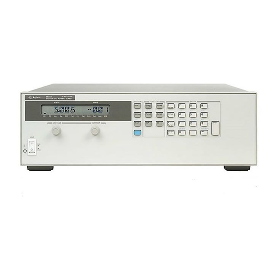
Keysight Model E4356A Telecommunications DC Power Supply Operating and Programming Guide... -
Page 3: Limitation Of Warranty
Export price). If Keysight Technologies is unable, within a reasonable time to repair or replace any product to condition as warranted, the Customer shall be entitled to a refund of the purchase price upon return of the product to Keysight Technologies. -
Page 4: Safety Summary
Because of the danger of introducing additional hazards, do not install substitute parts or perform any unauthorized modification to the instrument. Return the instrument to a Keysight Technologies Sales and Service Office for service and repair to ensure that safety features are maintained. -
Page 5: Safety Symbol - Definitions
This document contains proprietary information protected by copyright. All rights are reserved. No part of this document may be photocopied, reproduced, or translated into another language without the prior consent of Keysight Technologies Company. The information contained in this document is subject to change without notice. -
Page 6: Declaration Page
Declaration Page... -
Page 7: Table Of Contents
Table of Contents Safety Summary Safety Symbol - Definitions Acoustic Noise Information Printing History Declaration Page Table of Contents 1 - GENERAL INFORMATION Introduction Safety Considerations Options Accessories Operator Replaceable Parts List Description Front Panel Programming Remote Programming Analog Programming Output Characteristic Output Ranges Downprogramming... - Page 8 Selftest Errors Power-On Error Messages Checksum Errors. Runtime Error Messages 4 - USER CONNECTIONS Rear Panel Connections Load Wire Selection Analog Connector Connecting the Power supply to the Load Output Isolation Capacitive Loads Inductive Loads Battery Charging Local Voltage Sensing Remote Voltage Sensing Setting Up Remote Sense Operation Connecting the Sense Leads...
- Page 9 Setting the GPIB Address Changing the Power supply GPIB Address Assigning the GPIB Address In Programs DOS Drivers Types of Drivers Error Handling Keysight BASIC Controllers Sample Program Code SCPI Confirmed Commands NON-SCPI Commands 7 - LANGUAGE DICTIONARY Introduction Parameters...
- Page 10 *RCL *RST *SAV *SRE *STB? *TRG *TST? *WAI Description Of Subsystem Commands ABOR Calibration Commands Current Subsystem CURR CURR:TRIG CURR:PROT:STAT Digital Subsystem DIG:DATA Display Subsystem DISP DISP:MODE DISP:TEXT Initiate Subsystem INIT INIT:CONT Measure Subsystem MEAS:CURR? MEAS:VOLT? Output Subsystem OUTP OUTP:PROT:CLE OUTP:PROT:DEL OUTP:REL OUTP:REL:POL Status Subsystem...
- Page 11 Operation Status Group Register Functions Register Commands Questionable Status Group Register Functions Register Commands Standard Event Status Group Register Functions Register Commands Status Byte Register The MSS Bit The RQS Bit Output Queue Service Request Enable Register Inhibit/Fault Indicator RI (Remote Inhibit) DFI (Discrete Fault Indicator) Initial Conditions At Power On Status Registers...
- Page 12 Introduction Areas of Difference Chapter 2 Differences Voltage and Current Values – page 2-4 Verification Test Record – page 2-19 Chapter 3 Differences Initialization Program Listing - page 3-38 Chapter 5 Differences INDEX KEYSIGHT SALES AND SUPPORT OFFICES Manual Updates...
-
Page 14: General Information
Appendix G for COMPatibility commands SCPI programming examples SCPI language dictionary Chapter 2 Installing the Keysight VXI plug&play instrument driver NOTE: The driver must be installed on your pc to access the on-line information. Drivers are available on the web at www.keysight.com/go/drivers. -
Page 15: Options
, harmonized, with IEC 309 32A/220V plug Power cord, 10 AWG, UL listed, CSA certified, with NEMA L6-30P-30A/250V locking plug Rack mount kit (Keysight 5062-3977) Support rails (E3663A) are required. Rack mount kit with handles (Keysight 5062-3983) Support rails (E3663A) are required. Service addendum Accessories Table 1-3. -
Page 16: Description
Description The Keysight E4356A is a unipolar, GPIB programmable power supply, which is programmable locally from the front panel or remotely via a rear-panel analog control port. Operational features include: Constant voltage (CV) or constant current (CC) output over the rated output range. -
Page 17: Output Characteristic
Output Characteristic The power supply can operate in either CV (constant voltage) or CC (constant current) over its output voltage and current ratings (see Figure 1-l). Although the power supply can operate in either mode, it is designed as a constant voltage source. This means that the unit turns on in constant voltage mode with the output voltage rising to its Vset value. -
Page 18: Installation
Until you have checked out the power supply save the shipping carton and packing materials in case the power supply has to be returned to Keysight Technologies. If you return the power supply for service, attach a tag identifying the model number and the owner. -
Page 19: Location And Temperature
Temperature Performance A variable-speed fan cools the unit by drawing air through the sides and exhausting it out the back. Using Keysight rack mount or slides will not impede the flow of air. The temperature performance is as follows: The unit operates without loss of performance within the temperature range of 0 °C to 45 °C. - Page 20 The power cord supplied with power supply may or may not include a power plug (see "Options" in Chapter l) at one end of the cord. Terminating connections and a ground lug are attached to the other end of the cord. See Figure 2-2 and proceed as follows: 1.
-
Page 21: Vxi Plug&Play Power Products Instrument Drivers
A comprehensive online programming reference is provided with the driver. It describes how to get started using the instrument driver with Keysight VEE, LabVIEW, and LabWindows. It includes complete descriptions of all function calls as well as example programs in C/C++ and Visual BASIC. -
Page 22: Turn-On Checkout
Turn-On Checkout Introduction This chapter provides a preliminary introduction to the power supply front panel. See Chapter 5 - "Front Panel" Note for more details. Successful tests in this chapter provide a high degree of confidence that the power supply is operating properly. For verification tests, see Appendix C - "Operation Verification”. -
Page 23: Using The Keypad
Using the Keypad Shifted Keys Some of the front panel keys perform two functions, one labeled in black and the other in blue. You access the blue function by first pressing the blue key, which is not labeled. When the Shift annunciator is on, you will know you have access to the key's shifted (blue) function. -
Page 24: Checking The Current Function
Press Program the OVP to 30 volts, which is less than the output voltage. Press 0.000 OVP voltage entered is less than the output voltage. This causes the OVP circuit to trip. The output drops to zero, CV turns off, and Prot turns on. -
Page 25: Checking The Save And Recall Functions
Turn off the power supply and remove the short from the output terminals. Checking The Save And Recall Functions Keysight E4356A power supplies have five nonvolatile memory storage locations (0 through 4). Proceed as follows: Make certain that the output is on (Dis annunciator is off). -
Page 26: Error Messages
The line fuse is located inside the power supply. To change it, proceed as follows: l. Turn off the front panel power switch and unplug the line cord from the power source. 2. Remove the power supply dustcover as follows: a. -
Page 27: Checksum Errors
Table 3-3. Power-On Selftest Errors Error Display Failed Test Error Display Failed Test Front Panel RAM Secondary RAM FP RAM SEC RAM Front Panel ROM checksum Secondary ROM checksum FP ROM SEC ROM EEPROM Secondary 5 V ADC SEC 5V reading CHKSUM Primary external RAM... -
Page 28: User Connections
User Connections Rear Panel Connections Make application load connections to the output terminals or bus bars, analog connector, and digital connector as shown on the rear-panel drawing for your model power supply. Make controller connections (GPIB and serial link) as shown in Figure 4-6 at the end of this chapter. -
Page 29: Capacitive Loads
If you need help in solving a stability problem, contact a Keysight service engineer through your local Sales and Support Office (see end of this guide). If the power supply output is rapidly programmed into capacitive loads, the unit may momentarily cross into constant current (CC) mode. -
Page 30: Inductive Loads
Output Safety Cover Analog Connector – Output Bus Bar – Local Sense Terminal + Local Sense Terminal + Output Bus Bar Signal Common Local Sense Jumpers Rear Knockouts Bottom Knockout Insert screwdriver blade in slot and pry out Bend along joint and break off WARNING DO NOT LEAVE UNCOVERED HOLES IN OUTPUT COVER. -
Page 31: Local Voltage Sensing
Local Voltage Sensing Your power supply was shipped set up for local sensing. This means that the unit will sense and regulate its output at the output terminals, not at the load. Since local sensing does not compensate for voltage drops across screw terminals, bus bars, or load leads, local sensing should only be used in applications that require low output current or where load regulation is not critical. -
Page 32: Ovp Considerations
For utmost voltage programming accuracy, the unit should be recalibrated with the DVM at the remote sensing points (see “Appendix B - Calibration”). If you need help in solving a stability problem with the power supply, contact a Keysight Service Engineer through Note your local Keysight Sales and Support Office. -
Page 33: Connecting One Power Supply To Multiple Loads
Load Connection Analog Connector Load Connect for remote sensing (optional) Connect for local sensing (default) Figure 4-5. Single Load Connection (Remote Sensing Optional) Connecting One Power supply To Multiple Loads Figure 4-6 shows how to connect a single power supply to more than one load. When connecting multiple loads to the power supply with local sensing, connect each load to the output bus bars with separate connecting wires. -
Page 34: Connecting Units In Series
Analog Connector Slave Unit Master Unit Program only the master. Set slave output and OVP slightly higher than the master to ensure that slave stays in CC mode Load Load Connection Only local sensing permitted Connect for optional remote sensing Figure 4-7. -
Page 35: External Voltage Control
Load Connection Analog Connector Load Program each unit for full load current and 1/2 the load voltage Connect for remote sensing (optional) WARNING FLOATING VOLTAGES MUST NOT EXCEED 240 VDC NO OUTPUT TERMINAL MAY BE MORE THAN 240 V FROM CHASSIS GROUND. Figure 4-8. -
Page 36: Controller Connections
Programming. Note from Figure 4-1 that you have three options for programming the current. You can use a voltage source that is positive, negative, or floating with respect to Common P. Do not exceed 15 V with respect to Common P. Make certain that the common connection for your voltage programming source is isolated from the load. - Page 37 From 1 to 16 direct supplies may be connected to 1 controller GPIB interface. Tighten connector thumbscrews by hand. Do not use a screwdriver. Do not stack more than 3 connectors on a GPIB receptacle. GPIB cable (see Accessories in Chapter 1) ...
-
Page 38: Front Panel Operation
Front Panel Operation Introduction This chapter shows you how to operate the front panel. It is assumed that you are familiar with the turn-on checkout procedure in Chapter 3. That chapter describes how to perform basic power supply functions from the control panel. operations that you can perform are: Enabling or disabling the power supply output. - Page 39 Figure 5-1. Front Panel Controls and Indicators Table 5-1. Front Panel Controls and Indicators (See Figure 5-1) Control or Function or Indication Indicator Display VOLTS Shows present output voltage of the power supply. AMPS Shows present output current of the power supply. Status Annunciators The power supply is in constant-voltage mode.
- Page 40 Table 5-1. Front Panel Controls and Indicators (continued) SYSTEM Keys When the power supply is under remote control, press to enable local operation. This control can be defeated by a lock-out command over the GPIB Press to display the power supply's GPIB address. You can change the address with the ENTRY keys Use to display error codes generated during remote operation.
-
Page 41: Programming The Output
OUT OF RANGE appears on the display. Figure 1-1 shows the general response of the E4356A power supply. Unless directed otherwise, always keep the output voltage and current within the boundaries of its operating line for the specified mode of operation (CV or CC). -
Page 42: Programming Current
Setting the OVP Level. Assuming that you have programmed the power supply for 45 volts, you can set the OVP level to 48 volts as follows: Press . The display will change from meter mode to indicate 0V, followed by the present OVP value. ... -
Page 43: Programming Overcurrent Protection
Programming Overcurrent Protection When enabled, overcurrent protection removes the power supply output whenever it goes into CC operation. This prevents the unit from indefinitely uniting the full programmed current to the load. Setting The OCP Protection. To activate overcurrent protection, press . -
Page 44: Saving And Recalling Operating States
Saving and Recalling Operating States You can save programming time by storing up to 5 operating states in nonvolatile memory. The front panel programming parameters that are saved are: Output voltage, Output current, *OVP voltage, OCP state (on or off), Output state (enabled or disabled). ... -
Page 45: Changing The Power Supply Gpib Address
1. As a stand-alone unit (the only unit at the address). It has a primary address in the range of 0 to 30. For example: 5 or 7. 2. As the direct unit in a serial link. It is the only unit connected directly to the GPIB bus. The primary address is unique and can be from 0 to 30. -
Page 46: Remote Programming
Suite P3, Ls Mesa, CA 91942, USA GPIB References The most important GPIB documents are your controller programming manuals - Keysight BASIC, GPIB Command Library for MS DOS, etc. Refer to these for all non-SCPI commands (for example: Local Lockout). -
Page 47: Gpib Capabilities Of The Power Supply
GPIB Capabilities of the Power supply All power supply functions except for setting the GPIB address are programmable over the IEEE 488 bus (also known as the General Purpose Interface Bus or "GPIB"). The IEEE 488.1 capabilities of the power supply are listed in the Supplemental Characteristics in Table A-2. -
Page 48: The Effect Of Optional Headers
Subsystem Commands. Subsystem commands (see Figure 6-1) perform specific power supply functions. They are organized into an inverted tree structure with the "root" at the top. Some are single commands while others are grouped under other subsystems. Figure 6-1. Partial Command Tree Traversing the Command Tree Figure 6-1 shows a portion of the subsystem command tree (you can see the complete tree in Figure 7-2). -
Page 49: Moving Among Subsystems
The optional header SOURCE precedes the current, digital, and voltage subsystems. This effectively makes :CURRENT, :DIGITAL, and :VOLTAGE root-level commands. Moving Among Subsystems In order to combine commands from different subsystems, you need to be able to restore the active path to the root. You do this with the root specifier (:). -
Page 50: Types Of Scpi Messages
Types of SCPI Messages There are two types of SCPI messages, program and response. A program message consists of one or more properly formatted SCPI commands sent from the controller to the power supply. The message, which may be sent at any time, requests the power supply to perform some action. ... - Page 51 The header is completely spelled out, such as VOLTAGE STATUS DELAY. Long Form The header has only the first three or four letters, such as VOLT STAT DEL. Short Form Short form headers are constructed according to the following rules: ...
-
Page 52: Boolean Data
SCPI Data Formats All data programmed to or returned from the power supply is ASCII. The data may be numerical or character string. Numerical Data Table 6-1 and Table 6-2 summarize the numerical formats. Table 6-1. Numerical Data Formats Symbol Data Form Talking Formats <NR1>... -
Page 53: Scpi Command Completion
SCPI Command Completion SCPI commands sent to the power supply are processed either sequentially or in parallel. Sequential commands finish execution before a subsequent command begins. A parallel command can begin execution while a preexisting command is still executing (overlapping commands). Commands that affect trigger actions are among the parallel commands. The *WAI, *OPC, and *OPC? common commands provide different ways of indicating when all transmitted commands, including any parallel ones, have completed their operations. -
Page 54: Changing Outputs By Trigger
Programming Voltage and Current The following statements program both voltage and current and return the actual output from the sense terminals: OUTP OFF Disable the output. VOLT 45;CURR 25 Program the voltage and current. VOLT?;CURR? Read back the programmed levels. OUTP ON Enable the output. -
Page 55: Saving And Recalling States
Saving and Recalling States You can remotely save and recall operating states. See *SAV and *RCL in "Chapter 7 - Language Dictionary" for the parameters that are saved and recalled. When you turn the power supply on, it automatically retrieves the state stored in location 0. When a power Note supply is delivered, this location contains the factory defaults (see *RST in Chapter 7). -
Page 56: Programming The Digital I/O Port
The remainder of this chapter addresses some system issues concerning programming. These are power supply addressing and the use of the following types of GPIB system interfaces: HP Vectra PC controller with Keysight 82335A GPIB Interface Command Library. IBM PC controller with National Instruments GPIB-PCII Interface/Handler. -
Page 57: Assigning The Gpib Address In Programs
1010 PS=706 !Statement for Keysight 82335A Interface 1010 ASSIGN @PS TO 706 ! Statement for Keysight BASIC Interface 1020 !Direct address. The power supply will respond if it is set to 6. or 6.0 1030 PS-70600 ! Statement for Keysight 82335A Interface... -
Page 58: Keysight Basic Controllers
DOS Drivers Types of Drivers The Keysight 82335A and National Instruments GPIB are two popular DOS drivers. Each is briefly described here. See the software documentation supplied with the driver for more details. Keysight 82335A Driver. For GW-BASIC programming, the GPIB library is implemented as a series of subroutine calls. - Page 59 SAMPLE FOR POWER SUPPLY AT STAND-ALONE ADDRESS 6. SEQUENCE SETS UP CV MODE OPERATION, FORCES UNIT TO SWITCH TO CC MODE, AND DETECTS AND REPORTS MODE CHANGE. ************************************************************************** HP Vectra PC Controller Using Keysight 82335A Interface ************************************************************************** ‘ < --------------- Merge SETUP.BAS here -------------------- >...
- Page 60 Programming Some Power supply Functions (continued) 1220 CALL IOENTER (PS,OEVENT) 'Read back event bit 1225 IF PCIB.ERR < > NOERR THEN ERROR PCIB.BASERR 1230 IF (OEVENT AND 1024) = 1024 THEN PRINT "Unit switched to CC mode." 1240 'Clear the status circuit 1245 CODES$ = "*CLS"...
- Page 61 Programming Some Power supply Functions (continued) 1130 'Enable Status Byte OPER summary bit 1135 CODES$ = "*SRE 128" :GOSUB 2000 1140 ‘ 1146 'Arm trigger circuit and send trigger to power supply 1150 CODES$ = "INITIATE;TRIGGER" :GOSUB 2000 1160 'Wait for unit to respond to trigger 1165 FOR I= 1 to 100 :NEXT I 1170...
- Page 62 3065 D$=RIGHT$(OUTPUT$,LEN(OUTPUT$)-(I-1)) 3070 OUTPUT(X)=VAL(D$) 3076 OUTPUT$=SPACE$(40) 'Clear string 3080 RETURN **************************************************************************************************** Controller Using Keysight BASIC ***************************************************************************************************** 1000 !Power supply at stand-alone address = 706 1005 OPTION BASE 1 1010 DIM Codes$[80],Response$[80],Mode$[32] 1015 1020 !Program power supply to CV mode with following voltage and current 1026 OUTPUT 706;"VOLTAGE 78;CURRENT 25”...
-
Page 63: Scpi Confirmed Commands 1
SCPI Confirmed Commands This power supply conforms to Version 1990.0. ABOR OUTP:PROT:DEL TRIG[:STAR]:DEL CAL[:STAT) OUTP:PROT:DEL? TRIG[:STAR]:DEL? [SOUR]:CURR[:LEV][:IMM][:AMPL] STAT:OPER[:EVEN]? TRIG[:STAR]:SOUR [SOUR]:CURR[:LEV][:IMMI[:AMPL] STAT:OPER:COND? TRIG[:STAR]:SOUR? (SOUR]:CURR[:LEV]:TRIG[:AMPL] STAT:OPER:ENAB [SOUR]:VOLT[:LEV][:IMMI[:AMPL] (SOUR]:CURR[:LEV]:TRIG[:AMPL]? STAT:OPER:ENAB? [SOUR]:VOLT[:LEV][:IMM][:AMPL]? [SOUR]:CURR:PROT:STAT STAT:OPER:NTR [SOUR]:VOLT[:LEV][:TRIG][:AMPL] [SOUR]:CURR:PROT:STAT? STAT:OPER:NTR? [SOUR]:VOLT[:LEV][:TRIG][:AMPL]? DISP[:WIND][:STAT] STAT:OPER:PTR [SOUR]:VOLT:PROT[:LEV] DISP[:WIND][:STAT]? STAT:OPER:PTR? [SOUR]:VOLT:PROT[:LEV]? DISP[:WIND]:TEXT[:DATA] STAT:PRES *CLS... -
Page 64: Language Dictionary
Language Dictionary Introduction This section gives the syntax and parameters for all the IEEE 488.2 SCPI commands and the Common commands used by the power supply. It is assumed that you are familiar with the material in Chapter 6 - "Remote Programming". That chapter explains the terms, symbols, and syntactical structures used here and gives an introduction to programming. -
Page 65: Description Of Common Commands
Description Of Common Commands Figure 7-1 shows the common commands and queries. These commands are listed alphabetically in the dictionary. If a command has a corresponding query that simply returns the data or status specified by the command, then both command and query are included under the explanation for the command. -
Page 66: Parameters Related Commands
*ESE Meaning and Type Event Status Enable Device Status Description This command programs the Standard Event Status Enable register bits. The programming determines which events of the Standard Event Status Event register (see *ESR?) are allowed to set the ESB (Event Summary Bit) of the Status Byte register. - Page 67 This query requests the power supply to identify itself. It returns a string composed of four fields separated by commas. Query Syntax *IDN? Returned Parameters <AARD> Field Information Keysight Technologies Manufacturer 4-digit model number followed by a xxxxA letter suffix nnnnA-nnnnn 10-character serial number or 0 <R>.xx.xx Revision levels of firmware Keysight Technologies,6681,0,A.00.01...
- Page 68 *OPC? Meaning and Type Operation Complete Device Status Description This query causes the interface to place an ASCII "1" in the Output Queue when all pending operations are completed. Pending operations are as defined for the *OPC command. Unlike *OPC, *OPC? prevents processing of all subsequent commands.
- Page 69 Command Syntax *PSC <bool> Parameters 0 | 1 | OFF | ON *PSC 0 *PSC 1 Example Query Syntax *PSC? Returned Parameters <NR1> 0 | 1 Related Commands *ESE *SRE *PSC causes a write cycle to nonvolatile memory. If *PSC is programmed to 0, then the *ESE and *SRE commands also cause a write cycle to nonvolatile memory.
- Page 70 *RST Meaning and Type Reset Device State Description This command resets the power supply to a factory-defined state as defined below. *RST also forces an ABORt command. Command State CAL:STAT OFF OUTP[:STAT] OFF CURR[:LEV][:IMM] * OUTP:PROT:DEL * CURR[:LEV]:TRIG * OUTP:REL[:STAT] OFF CURR:PROT:STAT OFF OUTP:REL:POL NORM DIG:DATA 0...
- Page 71 *SRE Meaning and Type Service Request Enable Device Interface Description This command sets the condition of the Service Request Enable Register. This register determines which bits from the Status Byte Register (see *STB for its bit configuration) are allowed to set the Master Status Summary (MSS) bit and the Request for Service (RQS) summary bit.
- Page 72 Query Syntax *STB? (Register binary value) Returned Parameters <NR1> (None) Related Commands *TRG Meaning and Type Trigger Device Trigger Description This command generates a trigger when the trigger subsystem has BUS selected as its source. The command has the same affect as the Group Execute Trigger (<GET>) command.
-
Page 73: Calibration Commands
Description Of Subsystem Commands Figure 7-2 is a tree diagram of the subsystem commands. Commands followed by a question mark (?) take only the query form. Except as noted in the syntax descriptions, all other commands take both the command and query form. The commands are listed in alphabetical order and the commands within each subsystem are grouped alphabetically under the subsystem. -
Page 74: Curr:prot:stat
Current Subsystem This subsystem programs the output current of the power supply. CURR CURR:TRIG These commands set the immediate current level or the pending triggered current level of the power supply. The immediate level is the current programmed for the output terminals. The pending triggered level is a stored current value that is transferred to the output terminals when a trigger occurs. -
Page 75: Display Subsystem
Digital Subsystem This subsystem programs the control port on the back of the power supply when it is configured for Digital I/O operation. DIG:DATA This command sets and reads the power supply digital control port when that port is configured for Digital I/O operation. Configuring of the port is done via an internal jumper (see Appendix F). -
Page 76: Disp:mode
DISP:MODE Switches the display between its normal metering mode and a mode in which it displays text sent by the user. The command uses the character data <CRD> format. Command Syntax DISPlay[:WINDow]:MODE NORMalITEXT Parameters <CRD> NORMal | TEXT *RST Value NORM DISP:MODE NORM DISPLAY:MODE NORMAL... -
Page 77: Initiate Subsystem
Initiate Subsystem This subsystem enables the trigger system. INIT INIT:CONT When a trigger is enabled with this command, an event on a selected trigger source causes the specified trigging action to occur. If the trigger subsystem is not enabled, all trigger commands are ignored. If INIT:CONT is OFF, then INIT enables the trigger subsystem only for a single trigger action. -
Page 78: Outp:prot:cle Outp:prot:del
Output Subsystem This subsystem controls the power supply's voltage and current outputs and an optional output relay. OUTP This command enables or disables the power supply output. The state of a disabled output is a condition of zero output voltage and a model-dependent minimum source current (see Table 7-1). The query form returns the output state. Commandd Syntax OUTPut[:STATe] <bool>... -
Page 79: Outp:rel
OUTP:REL This command is valid only if the power supply is configured for the optional relay connector. Programming ON closes the relay contacts; programming OFF opens them. The relay is controlled independently of the output state. If the power supply is supplying power to a load, that power will appear at the relay contacts during switching. If the power supply is not configured for the relay option, sending either relay command generates an error. -
Page 80: Status Operation Registers
Status Operation Registers The bit configuration of all Status Operation registers is shown in the following table. See "Chapter 8 - Status Reporting" for more explanation of these registers. Bit Configuration of Operation Registers 15-12 Bit Position Bit Name 2048 1024 Bit Weight CAL = Interface is computing new calibration constants;... -
Page 81: Stat:oper:ntr Stat:oper:ptr
STAT:OPER:NTR STAT:OPER:PTR These commands set or read the value of the Operation NTR (Negative-Transition) and PTR (Positive-Transition) registers. These registers serve as polarity filters between the Operation Enable and Operation Event registers to cause the following actions: When a bit in the Operation NTR register is set to 1, then a 1-to-0 transition of the corresponding bit in the Operation Condition register causes that bit in the Operation Event register to be set. -
Page 82: Stat:ques:cond
STAT:QUES:COND? This query returns the value of the Questionable Condition register. That is a read-only register which holds the real-time (unlatched) questionable status of the power supply. Query Syntax STATus:QUEStionable:CONDition? (None) Parameters STAT:QUES:COND? STATUS:QUESTIONABLE:CONDITION? Examples (Register value) Returned Parameters <NR1> (None) Related Commands STAT:QUES:ENAB... -
Page 83: Syst:lang
System Commands System commands query error messages and software versions, and program system language functions. SYST:ERR? This query returns the next error number followed by its corresponding error message string from the remote programming error queue. The queue is a FIFO (first-in, first-out) buffer that stores errors as they occur. As it is read, each error is removed from the queue. -
Page 84: Trig:sour
This command selects the trigger source. Since the power supply has no other trigger source than the GPIB bus, this command need not be used. It is included in the command set to provide programming compatibility with other instruments (such as the Keysight Electronic Load family) that may have more than one trigger source. Command Syntax TRIGer:SOURce <CRD>... -
Page 85: Volt:prot
Command Syntax [SOURce]:VOLTage[:LEVel][:IMMediate][AMPLitude] <NRf+> [SOURce][:VOLTage[:LEVel]:TRIGgered[:AMPLitude] <NRf+> Table 7-1 Parameters Default Suffix Table 7-1 *RST Value VOLT 200 MA VOLTAGE:LEVEL 200 MA Examples VOLTAGE:LEVEL:IMMEDIATE:AMPLITUDE 2.5 VOLT:TRIG 20 VOLTAGE:LEVEL:TRIGGERED 20 Query Syntax [SOURce]:VOLTage[:LEVel][:IMMediate][:AMPLitude]? [SOURce]:VOLTage[:LEVel][:IMMediate][:AMPLitude]? [SOURce]:VOLTage[:LEVel][:IMMediate][:AMPLitude]? MIN [SOURce]:VOLTage[LEVel]:TRIGgered[:AMPLitude]? [SOURce]:VOLTage[LEVel]:TRIGgered[:AMPLitude]? MAX [SOURce]:VOLTage[:LEVel]:TRIGgered[:AMPLitude]? MIN <NR3> VOLT? and VOLT:TRIG? return presently programmed Returned Parameters immediate and triggered levels. -
Page 86: Command Summary
Command Summary This summary lists all power supply subsystem commands in alphabetical order, followed by all common commands in alphabetical order. See Table 7-1 for the command parameters accepted by the power supply. Command Summary Command Parameters Subsystem Commands (none) MEAS:CURR[:DC]? (none) MEAS:VOLT[:DC]? -
Page 87: Programming Parameters
Command Summary Command Parameters Subsystem Commands (none) ABOR (See Appendix A in the Operating Manual) <NRf+>[suffix] [SOUR]:CURR[:LEV][:IMM][:AMPL] (none) |MIN|MAX [SOUR]:CURR[:LEV][:IMM][:AMPL]? <NRf+>[suffix] [SOUR]:CURR[:LEV]:TRIG[:AMPL] (none) |MIN|MAX [SOUR]:CURR[:LEV]:TRIG[:AMPL]? 0 |l | ON|OFF [SOUR]:CURR:PROT:STAT (none) (SOUR]:CURR:PROT:STAT? <NRf> [SOUR]:DIG:DATA[:VAL] (none) [SOUR]:DIG:DATA[:VAL]? NORM|TEXT DISP[WIND]:MODE (none) DISP(WIND]:MODE? 0 |l | OFF|ON DISP[:WIND][:STAT] (none) -
Page 88: Status Reporting
Status Reporting Power supply Status Structure Figure 8-1 shows the status register structure of the power supply. The Standard Event, Status Byte, and Service Request Enable registers and the Output Queue perform standard GPIB functions as defined in the IEEE 488.2 Standard Digital Interface for Programmable Instrumentation. - Page 89 Table 8-2. Bit Configurations of Status Registers Signal Meaning Signal Meaning Operation Status Group Standard Event Status Group The interface is computing new Operation complete. calibration constants. The interface is waiting for a trigger. Query error. The power module is in constant Device-dependent error.
-
Page 90: Standard Event Status Group
Questionable Status Group Register Functions The Questionable Status registers record signals that indicate abnormal operation of the power supply. As shown in Figure 8-1, the group consists of the same type of registers as the Status Operation group. The outputs of the Questionable Status group are logically-ORed into the QUES(tionable) summary bit (3) of the Status Byte register. -
Page 91: Output Queue
Status Byte Register This register summarizes the information from all other status groups as defined in the "IEEE 488.2 Standard Digital Interface for Programmable Instrumentation" standard. The bit configuration is shown in Table 8-1. The register can be read either by a serial poll or by *STB?. Both methods return the same data, except for bit 6. Sending *STB? returns MSS in bit 6, while poring the register returns RQS in bit 6. -
Page 92: Status Register Programming Examples
Initial Conditions At Power On Status Registers When the power supply is turned on, a sequence of commands initializes the status registers. For the factory-default *RST power-on state, Table 8-4 shows the register states and corresponding power-on commands. Table 8-4. Default Power On Register States Register Condition Caused By... -
Page 93: Servicing An Operation Status Mode Event
Servicing an Operation Status Mode Event This example assumes you want a service request generated whenever the power supply switches to the CC (constant current) mode. From Figure 8-1, note that the required path is for a condition at bit 10 (CC) of the Operation Status register to set bit 6 (RQS) of the Status Byte register. -
Page 94: Specifications
Specifications are performance parameters warranted over the specified temperature range. Supplemental Characteristics are not warranted but are descriptions of performance determined either by design or type testing. Table A-1. Performance Specifications for Keysight E4356A Parameter Value 0 - 80 V (0 to 26A) - Page 95 Table A-2. Supplemental Characteristics for Keysight E4356A Parameter Value 81.9 V Output Programming Range Voltage: 30.71 A Current: 96 V Overvoltage Protection: 20 mV Typical Programming Resolution Voltage: 7.5 mA Current: 150 mV Overvoltage Protection: 1.5 V Accuracy Overvoltage Protection (OVP): ( @ 25 °C ...
- Page 96 Table A-2. Supplemental Characteristics (continued) Parameter Value 20 ms Command Processing Time (Average time for output voltage to change after receipt of digital data when the unit is connected directly to the GPIB Bus): 100 ms/200 ms Output Voltage Rise Time/Fall Time (time for output to change from 90 % to 10% or from 10% to 90% of its (excludes command processing time) total excursion with full resistive load)
- Page 97 Table A-2. Supplemental Characteristics (continued) CSA 22.2 No.231,IEC 348 Safety Compliance Complies with: UL 1244 Designed to comply with: CISPR-ll, Group 1, Class B RFI Suppression Complies with: 425.5 mm (16.75 in) Dimensions Width: Height (with removable feet): 145.1 mm (5.71 in) Depth (with safety cover): 640 mm (25.2 in) 27.7 kg (61 lb)
-
Page 98: Introduction
Shunt resistor For Calibration over the GPIB HP Vectra (or IBM compatible) with GPIB Controller GPIB Interface, or Keysight BASIC series General Procedure Because the power supply output must be enabled during calibration, voltages or currents hazardous to personnel and/or damaging to equipment can appear at the output terminals. -
Page 99: Disabling The Calibration Mode
Changing the Calibration Password The factory default password is the model number of your unit, such as E4356A. You can change the calibration password only when the power supply is in the calibration mode (which requires you to enter the existing password). Proceed as follows: 1. - Page 100 Table B-2. Typical Front Panel Calibration Procedure Action Display Response Enabling the Calibration Mode 1. Begin calibration by pressing PASWD 2. Enter calibration password from Entry keypad. If password is correct the Cal annunciator will come on. If password is incorrect, an error occurs PASSWD ERROR Note: The initial (factory-default) password is the model number of the power supply, but it can be changed (see "Changing the Password").
-
Page 101: Recovering From Calibration Problems
Calibration Example A sample calibration program is given at the end of this appendix. If your system is Keysight BASIC, you can use the program with very little modification. Otherwise, use it as a guide for writing your own program. -
Page 102: Cal:curr:lev
Calibration Language Dictionary The calibration commands are listed in alphabetical order. The format for each command follows that shown in Chapter 7. Calibration error messages that can occur during GPIB calibration are shown in Table B-3. CAL:CURR This command is used to calibrate the output current. The command enters current value that you obtain from an external meter. -
Page 103: Cal:stat
CAL:STAT This command enables and disables the calibration mode. The calibration mode must be enabled before the power supply will accept any other calibration commands. The first parameter specifies the enabled or disabled state. The second parameter is the password. It is required if the calibration mode is being enabled and the existing password is not 0. If the second parameter is not entered or is incorrect, an error is generated and the calibration mode remains disabled. -
Page 104: Basic Calibration Program
BASIC Calibration Program The following program can be run on any controller operating under Keysight BASIC. The assumed power supply address is 5 and calibration password is 4356. If required, change these parameters in the appropriate statements. ! Keysight BASIC Calibration Program... - Page 105 CLEAR SCREEN Password is optional - only required if set to non-zero value Default password is four-digit model number ! LINE 590 PASSWORD MUST BE EDITED FOR MODEL OTHER THAN E4356A OUTPUT @Ps;"CAL:STATE ON, 4356" OUTPUT @Ps;"VOLT:LEV 2" ! Refer to Table A-1 for correct shunt value for model being calibrated INPUT "ENTER VALUE 0F CURRENT SHUNT BEING USED",Shunt_val...
-
Page 106: Introduction
The following equipment is required to perform the tests: Table C-1. Equipment Required for Verification Tests Equipment Characteristics Recommended Model Resolution: 10 nV @ 1 V Keysight 3458A Digital Voltmeter Readout: 8 1/2 digits Accuracy: 20 ppm Guildline 9230/100 l00 A, 0.001 , 0.04%, 100 W... -
Page 107: Performing The Tests
Performing The Tests General Measurement Techniques Figure C-1 shows the setup for the tests. Be certain to use load leads of sufficient wire gauge to carry the output current (see Table 8-1). To avoid noise pickup, use coaxial cable or shielded pairs for the test leads. Programming the Power supply Appendix A lists the programming voltage and current ranges. -
Page 108: Current Programming And Readback Accuracy
Current Programming and Readback Accuracy This test verifies that the current programming and readback are within specification. Connect the appropriate current monitoring resistor (see Table C-1) as shown in Figure C-1(2). The accuracy of the resistor must be as specified in the table. Table C-3. -
Page 110: D - Error Messages
Error Messages Power supply Hardware Error Messages Front panel error messages resulting from selftest errors or runtime failures are described in “Chapter 3 - Turn-On Checkout”. Calibration Error Messages Front panel error messages resulting from calibration errors are described in Appendix B. System Error Messages System error messages are obtained remotely with the SYST:ERR? query or by pressing the front panel key. - Page 111 Table D-1. Summary of System Error Messages (continued) Error Error String [Description/Explanation/Examples] Number -141 Invalid character data [bad character, or unrecognized] -144 Character data too long [maximum length is 12 characters] -148 Character data not allowed [character data not accepted where positioned] -150 String data error [generic string error] -151...
-
Page 112: Line Voltage Conversion
Line Voltage Conversion SHOCK HAZARD. Hazardous voltage can remain inside the power supply even after it has been turned off. This procedure should only be done by qualified electronics service personnel. Line voltage conversion is accomplished by setting a line voltage select switch. Proceed as follows: 1. -
Page 114: Digital Connector
Digital Port Functions Digital Connector A 4-pin connector and a quick-disconnect mating plug are provided for digital input and output signals (see Figure F-l for wiring connections, and Table A-2 for electrical characteristics). This digital port can be configured to provide either Fault/Inhibit or Digital I/O functions. - Page 115 GPIB Figure F-2. Example of Inhibit Input In Figure F-3A, the FLT output is connected to a relay driver circuit that energizes a relay whenever a fault condition occurs in the power supply. The relay can be used to physically disconnect the output of the power supply from the load. The FLT output is generated by the logical ORing of the power supply's Operation, Questionable, and Event status summary bits (see "Chapter 8 - Status Reporting”...
-
Page 116: Changing The Port Configuration
Changing The Port Configuration As shipped from the factory, the digital port is configured for FLT/INH operation. You can change the configuration of the port to operate as a general-purpose digital input/output port to control your custom circuitry as shown in Figure F-4. To change the port configuration, you must move a jumper on the GPIB board. -
Page 117: Digital I/O Operation
Figure F-5. Digital l/O Port Applications Relay Link Operation The digital port can be configured to provide relay control outputs for the Keysight 59510A or 59511A Relay Accessory. Refer to Figure F-1 for the pin assignments of the mating plug. - Page 118 Figure F-6 shows how to connect your power supply to an Keysight 59510A or 59511A Relay Accessory when the digital port is configured for relay link operation. An error will be generated if you attempt to program the relay box without first configuring the digital port for relay link operation.
-
Page 120: Introduction
This means that you can program this power supply over the GPIB using the ARPS commands. Software that you have written for the autoranging power supplies can also be adapted to program this power supply. The Keysight E4356A Power supply's serial link is not supported by ARPS commands. You can use only Note a GPIB primary address for the power supply. - Page 121 These commands measure and read output voltage or current. VOLT? MEAS:VOLT? IOUT? MEAS:CURR? OVP x NOTE: OVP commands do not work with Keysight 603xA VOLT:PROT supplies. These commands program the overvoltage protection. OVP xV The OVP setting is programmed in either volts or millivolts. See OVP xMV Table 7-1 for the programming ranges of these commands.
- Page 122 Table G-1. ARPS Commands (continued) ARPS Command Description Similar SCPI Command This command resets the power supply if the output is disabled by OUTP:PROT:CLE the overvoltage, remote inhibit, or foldback protection circuits. The power supply resets to the parameters stored for the power-on state.
- Page 123 Table G-1. ARPS Commands (continued) ARPS Command Description Similar SCPI Command This command reads which bits in the status register have been UNMASK? STAT:OPER:ENAB? enabled as fault conditions. The decimal equivalent of the total bit STAT:QUES:ENAB? weight of all enabled bits is returned. This command reads which bits have been set in the fault register.
-
Page 124: Introduction
This addendum contains information for troubleshooting and repairing the Keysight E4356A Telecommunications DC Power Supply. The standard service manual for the Keysight Series 667xA DC Power Supplies (p/n 5959-2583) is shipped with the Keysight E4356A when ordered with Option 0BN. This manual must be used together with this service addendum. -
Page 125: Verification Test Record – Page 2-19
Verification Test Record – page 2-19 Table 2-12. Verification Test Record for Keysight Model E4356A Model: Keysight E4356A Report No.____________ Date_____________ Test Description Minimum Recorded Maximum Measurement Specification Results* Specification Uncertainty Constant Voltage Tests Voltage Programming and Readback Low Voltage (0 V) V... -
Page 126: Chapter 3 Differences
Add the following lines after line 980: Change line 1030 to read: Change lines 660, 720, 1070, and 1600 to read: Chapter 5 Differences Table 5-3. Main Chassis Ref. Des. Keysight Part No. Description ELECTRICAL PARTS E4356-61023 Front panel pc assembly, tested 5063-4851... - Page 127 Table 5-4. A1 Front Panel Board Ref. Des. Keysight Part No. Description 5080-2278 Programmed ROM (installed in socket) Table 5-6. A2 GPIB Board Ref. Des. Keysight Part No. Description U106 5080-2243 Programmed ROM (installed in socket) Table 5-9. A5 Control Board Ref.
-
Page 128: Index
Index CAL CURR LEV, 103 CAL PASS, 103 —<— CAL SAVE, 103 CAL STAT, 104 <bool>, 51 CAL VOLT, 104 <NR1>, 51 CAL VOLT LEV, 104 <NR2>, 51 CAL VOLT PROT, 104 <NR3>, 51 calibration errors, 102 <NRf+>, 51 capacitive loads, 28 <NRf>, 51 cc mode, 16, 42 character strings, 51... - Page 129 connector Ouptut On/Off, 39 analog, 27 OV, 39 digital, 28 Prot Clear, 39 controller connections, 35 Protect, 39 linked, 35 Voltage, 39 stand-alone, 35 fuse conventions, 46 location, 25 CRD, 51 replacing, 25 current monitor resistor, 107 current programming, 41, 53 —G—...
- Page 130 load, inductive, 29 programming local voltage sensing, 30 analog, 16 location, 18 auto-parallel, 33 current, 41, 53 digital I/O, 55 —M— external voltage, 34 front panel, 15 master unit, 32 overcurrent protection (OCP), 42, 53 message terminator, 50 overvoltage protection (OVP), 40, 53 message unit parameters, 86 separator, 50...
- Page 131 data format, 51 DISP TEXT, 75 header path, 47 INIT, INIT CONT, 76 message structure, 49 MEAS CURR, MEAS VOLT, 76 message types, 49 OUTP, 77 message unit, 49 OUTP PROT CLE, OUTP PROT DEL, 77 multiple commands, 47 OUTP REL, 78 non-conformance, 62 OUTP REL POL, 78 program message, 49...
- Page 132 voltage programming, 40, 53 —W— voltage sensing, local, 30 voltage sensing, remote, 30 warranty, 2 VP, 27 wire capacity, 27 VXIplug&play, 13, 20 wire resistance, 27 wire size, 27 writing to the display, 54 Index 131...
-
Page 133: Keysight Sales And Support Offices
Keysight Sales and Support Offices For more information, call your local Keysight sales office listed in your telephone directory or a Keysight regional office listed below for location of your nearest sales/support office. United States of America: Europe: Keysight Technologies Company... - Page 134 This information is subject to change without notice. © Keysight Technologies 1999, 2015 Edition 2, January 2015 5964-8166 www.keysight.com...
Need help?
Do you have a question about the E4356A and is the answer not in the manual?
Questions and answers