Table of Contents
Advertisement
Advertisement
Table of Contents

Related Manuals for Keysight N5741A


Summary of Contents for Keysight N5741A
- Page 1 Keysight Series N5700 System DC Power Supply User’s Guide...
-
Page 4: Legal Notices
Legal Notices Waste Electrical and Assistance Electronic Equipment (WEEE) © Keysight Technologies 2004 - 2014 This product comes with the standard Directive 2002/96/EC product warranty. Warranty options, No part of this document may be extended support contacts, product photocopied, reproduced, or translated to... -
Page 5: Safety Notices
Terminal is at earth impaired if it is used in a manner not product. Return the product to a Keysight potential. specified in the operation instructions. Sales and Service Office for service and... - Page 6 In the United States: (800) 829-4444 In Europe: 31 20 547 2111 In Japan: 0120-421-345 Or use our Web link for information on contacting Keysight in your country or specific location: www.keysight.com/find/assist Or contact your Keysight Technologies Representative.
-
Page 7: Table Of Contents
Contents 1 Quick Reference ..........................9 The Keysight N5700 DC Power Supplies – At a Glance ......10 The Front Panel - At a Glance ................. 12 The Rear Panel – At a Glance ................. 14 2 Installation............................17 General Information ..................18 Inspecting the Unit ................... - Page 8 6 Programming Examples ........................83 Output Programming Example ................ 84 Trigger Programming Example ................ 86 A Specifications ........................... 89 Performance Specifications ................90 Supplemental Characteristics ................. 91 Outline Diagram ....................93 B Verification and Calibration......................95 Verification ......................96 Calibration ......................115 C Service .............................117 Types of Service Available................
-
Page 9: Quick Reference
Quick Reference The Keysight N5700 DC Power Supplies – At a Glance ......10 The Front Panel - At a Glance ................. 12 The Rear Panel – At a Glance ................. 14 This chapter concisely describes the Keysight Technologies Series N5700 Power Supplies. -
Page 10: The Keysight N5700 Dc Power Supplies - At A Glance
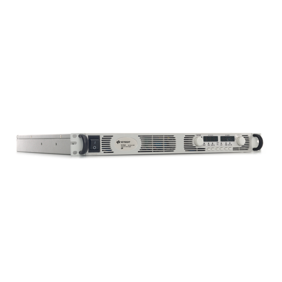
1 Quick Reference The Keysight N5700 DC Power Supplies – At a Glance The Keysight Technologies Series N5700 System DC Power Supplies are general-purpose, 1U (rack unit) high, switching power supplies that are available with a wide variety of output voltage and current ratings. -
Page 11: Programmable Functions
Model Ratings Model Voltage Current Model Voltage Current Range Range Range Range N5741A 0 – 6V 0 – 100A N5761A 0 – 6V 0 – 180A N5742A 0 – 8V 0 – 90A N5762A 0 – 8V 0 – 165A N5743A 0 –... -
Page 12: The Front Panel - At A Glance
1 Quick Reference The Front Panel - At a Glance VOLTAGE CURRENT DC VOLTS DC AMPS LIMIT/ UVL OCP/488 OUT ON PROT FINE POWER 1 – VOLTAGE knob Voltage function: Adjusts the output voltage, the over-voltage protection level, and the under-voltage limit. - Page 13 Quick Reference 1 9 – LAN button View address: Press LAN to view the IP and Ethernet address. The display first scrolls through the four segments of the IP address, followed by the six segments of the Ethernet (EA) address. Press any key to turn the address display off. Reset address: Press and hold the LAN button for three seconds.
-
Page 14: The Rear Panel - At A Glance
1 Quick Reference The Rear Panel – At a Glance 10/100 Ethernet LINK GPIB J2 SW1 1 2 3 4 5 6 7 8 9 ANALOG PROGRAMMING AC INPUT +S+LS NC -LC-S NOT ACTIVE 80V - 600V 750W 6V - 60V 1500W 1 –... - Page 15 Quick Reference 1 J2 Sense Connector 1 – Remote sense (+) 2 – Local sense (+) 3 – Not used 4 – Local sense (–) 5 – Remote sense (–) The factory-shipped configuration is shown in the figure. SW1 Setup Switch The factory-shipped setting is Down for all switches.
- Page 16 1 Quick Reference J1 Analog Programming Connector Current Program Voltage Monitor Chassis Common Voltage Program Common (-S) Chassis Common CV / CC Local / Analog Enable IN Parallel Enable OUT Current Monitor Shut Off Current Prog. Return Power Supply OK Voltage Prog.
-
Page 17: Installation
Before getting started, check the list under “Items Supplied” and verify that you have received these items with your instrument. If anything is missing, please contact your nearest Keysight Sales and Service Office. Series N5700 User’s Guide... -
Page 18: General Information
(only used for 6V to 60V units) Documentation Set Contains User’s Guide with Product Reference CD-ROM Certificate of Calibration A certificate of calibration referenced to the serial number Automation-Ready E2094N - contains Keysight IO Libraries Suite CD-ROM Accessories Item Description N5740A Rack-mount slide kit for installing in system II cabinets Series N5700 User’s Guide... -
Page 19: Inspecting The Unit
Do not operate the power supply in an area where the ambient temperature exceeds 40° C. Keysight N5700 power supplies generate magnetic fields, which may affect the NOTE operation of other instruments. If your equipment is susceptible to magnetic fields, do not position it adjacent to the power supply. - Page 20 Do not block the air intake at the front, or the exhaust at the rear of the unit. The Keysight N5700 power supplies can be mounted in a standard 19- inch rack panel or cabinet. They are designed to fit in one rack unit (1U) of space.
-
Page 21: Connecting The Line Cord
AC cord is plugged into a grounded AC receptacle. If the wrong power cord was shipped with your unit, contact your nearest Keysight Sales and Service Office. Input Connections for 1500W units Connection of this power supply to an AC power source should be made by a CAUTION qualified electrician or other qualified personnel. - Page 22 2 Installation • Unscrew the base of the strain relief from the wire compression nut. Place the locknut inside the AC input cover with the flat side of the nut against the cover. Insert the base through the outside opening of the AC input cover. Screw the base securely onto the locknut from the outside (17 ft-lbs).
-
Page 23: Connecting The Load
Installation 2 Connecting the Load SHOCK HAZARD Turn off AC power before making rear panel connections. WARNING All wires and straps must be properly connected with screws securely tightened. As further explained in this section, the following factors should be considered when selecting wiring to connect the load to the power supply: •... - Page 24 2 Installation Cross section Resistance Maximum length in meters to limit voltage to 1 V for 5 A for 10 A for 20A for 50A for 150A Ω/kilometer 8.21 24.0 12.0 5.09 39.2 18.6 3.39 59.0 29.4 14.8 1.95 51.2 25.6 10.2 1.24...
- Page 25 Installation 2 Install the shield after you have finished connecting the load wires. Shield Load Connections for 80V to 600V Models SHOCK HAZARD Hazardous voltages may exist at the outputs and the load WARNING connections when using a power supply with a rated output greater than 40V. To protect personnel against accidental contact with hazardous voltages, ensure that the load and its connections have no accessible live parts.
-
Page 26: Output Voltage Sensing
2 Installation • Loosen the two chassis screws marked A halfway. • Assemble the protective shield to the chassis and tighten the two screws to fix the shield to the chassis. Screw tightening torque: 4.8-5.3 in-lb • Tighten the wires to one of the shield sides using tie-wrap or equivalent. -
Page 27: Local Sensing
Installation 2 The J2 connector plug specifications are as follows: Plug Type: MC 1.5/5-ST-3.81, Phoenix Wire Size: AWG 28 to AWG 16 Stripping Length: 7 mm (0.28 in.) Torque: 0.22 – 0.25 Nm (1.95 – 2.21 in-lb.) Local Sensing The power supply is shipped with the rear panel J2 sense connector wired for local sensing of the output voltage. -
Page 28: Load Considerations
2 Installation To configure the power supply for remote sensing: • Turn off the power supply. • Remove the local sense jumpers from the J2 connector. • Connect the negative sense lead to terminal 5 (-S) and the positive sense lead to terminal 1 (+S). Make sure that the connector plug is securely inserted into the connector body. - Page 29 Installation 2 If remotely located distribution terminals are used, as shown in the following figure, the power supply output terminals should be connected to the remote distribution terminals by a pair of twisted and/or shielded wires. Connect each load to the distribution terminals separately.
-
Page 30: Parallel Connections
2 Installation Battery Charging If a battery or external voltage source is connected across the output and the CAUTION output is programmed below the battery or external voltage source, the power supply will continuously sink current from the external source. This could damage the power supply. -
Page 31: Setting Up The Master Unit
Installation 2 As short as possible MASTER Twisted POWER SUPPLY pair J1-25 Parallel LOAD Current Program J1-8 J1-12 J1-10 SLAVE POWER SUPPLY Local Sensing Twisted pair As short as possible MASTER Twisted POWER SUPPLY pair J1-25 Parallel LOAD Current Program J1-8 J1-12 J1-10 SLAVE... -
Page 32: Series Connections
2 Installation Setting up the Slave Units Set the rear panel setup switch SW1 position 2 to it’s up position. Connect J1 pin 10 (Current Program) of the slave unit to J1 pin 25 (Parallel) of the master unit. Also connect a short between J1 pin 8 and J1 pin 12. - Page 33 Installation 2 It is recommended that diodes be connected in parallel with each output to prevent reverse voltage during start up sequence or in case one unit shuts down. Each diode should be rated to at least the rated output voltage and output current of the power supply. POWER POWER SUPPLY...
-
Page 34: J1 Connector Connections
2 Installation J1 Connector Connections SHOCK HAZARD There is a potential shock hazard at the J1 connector when WARNING using a power supply with a rated output greater than 40V. Ensure that the load wiring insulation rating is greater than or equal to the maximum output voltage of the power supply. -
Page 35: Operating The Power Supply Locally
Operating the Power Supply Locally Turn-On Check-Out ................... 36 Normal Operation ....................38 Protection Functions ..................39 Output On/Off Controls..................42 Analog Programming of Output Voltage and Current ......... 44 This chapter contains examples on how to operate your power supply from the front panel. -
Page 36: Turn-On Check-Out
3 Operating the Power Supply Locally Turn-On Check-Out Before Turn-On Ensure that the power supply is configured as follows: • The unit is connected to the proper AC mains (see chapter 2). • The POWER switch is in the off position. •... - Page 37 Operating the Power Supply Locally 3 • Use the voltage knob and raise the output voltage of the unit until it approaches the OVP setting. Check to make sure that the output voltage cannot be set higher than the OVP setting. •...
-
Page 38: Normal Operation
3 Operating the Power Supply Locally Normal Operation The power supply has two basic operating modes: constant voltage and constant current mode. In constant voltage mode, the power supply regulates the output voltage at the selected value, while the load current varies as required by the load. -
Page 39: Protection Functions
Operating the Power Supply Locally 3 CV/CC Mode Crossover If the power supply is in constant voltage mode and the load current increases above the current limit setting, the power supply switches to constant current mode. If the load decreases below the current limit setting, the power supply switches to constant voltage mode. - Page 40 3 Operating the Power Supply Locally • Turn the AC power off, wait a few seconds, and turn it on. • Turn the output off, then on again using the Shut Off pin on the J1 connector. This only applies in Auto-Restart mode. •...
- Page 41 Operating the Power Supply Locally 3 Over-Temperature Protection The over-temperature protection circuit shuts down the power supply before the internal components can exceed their safe internal operating temperature. This can occur if there is a cooling fan failure. When an OTP condition occurs, the output is disabled, the display shows O7P, the PROT indicator blinks, and the OT status bit is set in the Questionable Condition status register.
-
Page 42: Output On/Off Controls
3 Operating the Power Supply Locally Output On/Off Controls The Output On/Off controls turn the power supply output on or off. This can be done with the front panel OUT ON button or from the rear panel J1 connector. With the output off, adjustments can be made to the power supply or the load without shutting off AC power. - Page 43 Operating the Power Supply Locally 3 When an on-to-off transition is detected at the Shut-Off input, the Shut- Off function enables or disables the output according to the signal level or the open/short applied to J1 pin 15. When the output has been disabled by the Shut-Off function, the display shows SO to indicate the output is disabled.
-
Page 44: Analog Programming Of Output Voltage And Current
3 Operating the Power Supply Locally Power Supply OK Signal The Power Supply OK signal on the J1 connector indicates a fault condition in the power supply. J1 pin 16 is a TTL output signal. Pins 2 and 3, which are connected internally, are the signal common. All pins are optically isolated from the power supply output. - Page 45 Operating the Power Supply Locally 3 The J1 connector also provides monitoring signals for the output voltage and output current. The programming range and monitoring signal range can be selected using the SW1 setup switch. With analog programming enabled, you cannot program the output voltage or NOTE current using the front panel knobs or the remote interface.
- Page 46 3 Operating the Power Supply Locally • Set the programming sources to the desired levels and turn the power supply on. Adjust the programming sources to change the power supply output. The analog control circuits let you set the output voltage and current limit up to 5% over the model-rated maximum value.
- Page 47 Operating the Power Supply Locally 3 • Set the programming resistors to the desired resistance and turn the power supply on. Adjust the resistors to change the power supply output. The analog control circuits let you set the output voltage and current limit up to 5% over the model-rated maximum value.
-
Page 49: Operating The Power Supply Remotely
Operating the Power Supply Remotely Connecting to the Interfaces ................50 SCPI Commands – an Introduction ..............59 This chapter contains information on how to configure the three remote interfaces that are provided on the back of the instrument. In most cases you can connect your power supply to any one of these interfaces and be up and running with a minimum amount of configuration. -
Page 50: Connecting To The Interfaces
General Purpose Interface Bus (GPIB). The following figure illustrates a typical GPIB interface system. If you have not already done so, install the Keysight IO Libraries Suite from the Automation-Ready CD-ROM that is shipped with your product. - Page 51 The VISA address is: USB0::2391::2055::serialnumber::0:INSTR NOTE where 2391 is the Keysight code, 2055 is the N5700 code, and serialnumber is the 10-character serial number located on the label on the side of the unit. You can now use Interactive IO within the Connection Expert to communicate with your instrument, or you can program your instrument using the various programming environments.
- Page 52 6-character model number (e.g. N5741A), and serialnumber is 5th through the 9th character of the 10-character serial number located on the label on the side of the unit (e.g. H1234 if the serial number is US24H12345). A-N5741A-H1234 is an example of a hostname.
- Page 53 LAN. They are typically small, with no centrally-managed resources. If you have not already done so, install the Keysight IO Libraries Suite from the Automation-Ready CD-ROM that is shipped with your product.
- Page 54 These latter methods are a convenient way to communicate with the power supply without using I/O libraries or drivers. Ethernet Connection Monitoring Keysight N5700 power supplies that have the LXI label on the front panel provide Ethernet connection monitoring. With Ethernet connection monitoring, the instrument’s LAN port is continually...
- Page 55 Type the SCPI commands at the prompt. Using Sockets Keysight instruments have standardized on using port 5025 for SCPI socket services. A data socket on this port can be used to send and receive ASCII/SCPI commands, queries, and query responses. All commands must be terminated with a newline for the message to be parsed.
- Page 56 4 Operating the Power Supply Remotely Service requests are enabled for control sockets using the Service Request Enable register. Once service requests have been enabled, the client program listens on the control connection. When SRQ goes true the instrument will send the string “SRQ +nn” to the client. The “nn”...
- Page 57 Operating the Power Supply Remotely 4 Subnet Mask This value enables the instrument to determine whether a client IP address is on the same local subnet. When a client IP address is on a different subnet, all packets must be sent to the Default Gateway. A value of 0.0.0.0 or 255.255.255.255 disables subnetting.
- Page 58 Get IP Address Automatic Alternate DNS server Blank IP Address 169.254.57.0 Desired Hostname A-N57xxA-xxxxx Subnet Mask 255.255.0.0 Description Keysight N57xxA (serial#) Default Gateway 0.0.0.0 mDNS Enabled Enabled DNS Server Address Configuration Automatic Password Blank Preferred DNS server Blank Series N5700 User’s Guide...
-
Page 59: Scpi Commands - An Introduction
Operating the Power Supply Remotely 4 SCPI Commands – an Introduction SCPI (Standard Commands for Programmable Instruments) is an ASCII-based instrument command language designed for test and measurement instruments. SCPI commands are based on a hierarchical structure, also known as a tree system. In this system, associated commands are grouped together under a common node or root, thus forming subsystems. - Page 60 4 Operating the Power Supply Remotely previous command in the message up to and including the last colon separator. An example of a message with two commands is: OUTPut:STATe ON;PROTection:CLEar which shows the use of the semicolon separating the two commands, and also illustrates the command path concept.
- Page 61 Operating the Power Supply Remotely 4 In the previous examples, the upper-case letters indicate the abbreviated spelling for the keyword. For shorter program lines, you can send the abbreviated form. For better program readability, you can send the long form. For example, VOLT and VOLTage are both acceptable forms.
-
Page 62: Parameter Types
4 Operating the Power Supply Remotely Parameter Types Data programmed or queried from the power supply is ASCII. The data may be numerical or character string. Numeric Parameters Symbol Response Formats <NR1> Digits with an implied decimal point assumed at the right of the least-significant digit. - Page 63 Device Clear. Device Clear also prepares the power supply to accept a new command string. The following statement shows how to send a device clear over the GPIB interface using Keysight BASIC: CLEAR 705 IEEE-488 Device Clear...
-
Page 65: Language Reference
Language Reference SCPI Command Summary ................66 Calibration Commands ..................68 Measure Commands..................69 Output Commands .................... 70 Source Commands .................... 71 Status Commands ..................... 73 System Commands ................... 79 Trigger Commands .................... 81 This section gives the syntax and parameters for all the IEEE 488.2 SCPI Subsystem commands and Common commands used by the power supply. -
Page 66: Scpi Command Summary
5 Language Reference SCPI Command Summary Some [optional] commands have been included for clarity. All settings commands NOTE have a corresponding query. Subsystem Commands SCPI Command Description ABORt Aborts the triggered action CALibrate :CURRent[:LEVel] Calibrates the output current programming :DATA <NRf> Enters the calibration value :DATE <”SPD”>... -
Page 67: Common Commands
Language Reference 5 SCPI Command Description STATus :OPERation [:EVENt]? Returns the value of the operation event register :CONDition? Returns the value of the operation condition register :ENABle <NRf> Enables specific bits in the Event register :NTRansition<NRf> Sets the Negative transition filter :PTRansition<NRf>... -
Page 68: Calibration Commands
5 Language Reference Calibration Commands Calibration commands let you enable and disable the calibration mode, change the calibration password, calibrate current and voltage programming, and store new calibration constants in nonvolatile memory. If calibration mode has not been enabled with CALibrate:STATe, the calibration NOTE commands will generate an error. -
Page 69: Measure Commands
Language Reference 5 CALibrate:STATe ON|OFF [,<password>] CALibrate:STATe? This command enables/disables calibration mode. Calibration mode must be enabled for the power supply to accept any other calibration commands. The first parameter specifies the enabled or disabled state On (1) or Off (0). The second parameter is the password. A password is required if calibration mode is being enabled and the existing password is not 0. -
Page 70: Output Commands
5 Language Reference Output Commands Output commands enable the output, power-on, and protection functions. OUTPut[:STATe] ON|OFF OUTPut[:STATe]? This command enables or disables the specified output(s). The enabled state is On (1); the disabled state is Off (0). The state of a disabled output is a condition of zero output voltage and a zero source current (see *RST). -
Page 71: Source Commands
Language Reference 5 Source Commands Source commands program the voltage, current, triggered, and protection functions. [SOURce:]CURRent[:LEVel][:IMMediate][:AMPLitude] <value>|MIN|MAX [SOURce:]CURRent[:LEVel][:IMMediate][:AMPLitude]? [MIN|MAX] [SOURce:]CURRent[:LEVel]:TRIGgered[:AMPLitude] <value>|MIN|MAX [SOURce:]CURRent[:LEVel]:TRIGgered[:AMPLitude]? [MIN|MAX] These commands set the immediate and the triggered output current level. The values are programmed in amperes. The immediate level is the output current setting. - Page 72 5 Language Reference [SOURce:]VOLTage:LIMit:LOW <value>|MIN|MAX [SOURce:]VOLTage:LIMit:LOW? [MIN|MAX] This command sets the low voltage limit of the output. When a low voltage limit has been set, the instrument will ignore any programming commands that attempt to set the output voltage below the low voltage limit.
-
Page 73: Status Commands
Language Reference 5 Status Commands Status commands program the power supply’s status registers. As shown in the following figure, the power supply has three groups of status registers; Operation, Questionable, and Standard Event. The Operation and Questionable status groups each consist of the Condition, Enable, and Event registers and NTR and PTR filters. - Page 74 5 Language Reference The Standard Event group is programmed with Common commands as described later in this section. Common commands also control additional status functions such as the Service Request Enable and the Status Byte registers. STATus:PRESet This command sets all defined bits in the Operation and Questionable PTR registers.
- Page 75 Language Reference 5 STATus:OPERation:NTR <value> STATus:OPERation:PTR <value> STATus:OPERation:NTR? STATus:OPERation:PTR? These commands set or read the value of the Operation NTR (Negative-Transition) and PTR (Positive-Transition) registers. These registers serve as polarity filters between the Operation Condition and Operation Event registers to cause the following actions: When a bit in the Operation NTR register is set to 1, then a 1-to-0 ...
- Page 76 5 Language Reference STATus:QUEStionable:ENABle <value> STATus:QUEStionable:ENABle? This command and its query set and read the value of the Questionable Enable register. This register is a mask for enabling specific bits from the Questionable Event register to set the questionable summary bit (QUES) of the Status Byte register. This bit (bit 3) is the logical OR of all the Questionable Event register bits that are enabled by the Questionable Status Enable register.
- Page 77 Language Reference 5 *ESE *ESE? This command programs the Standard Event Status Enable register bits. The programming determines which events of the Standard Event Status Event register (see *ESR?) are allowed to set the ESB (Event Summary Bit) of the Status Byte register. A "1" in the bit position enables the corresponding event.
- Page 78 5 Language Reference *SRE *SRE? This command sets the condition of the Service Request Enable Register. This register determines which bits from the Status Byte Register are allowed to set the Master Status Summary (MSS) bit and the Request for Service (RQS) summary bit. A 1 in any Service Request Enable Register bit position enables the corresponding Status Byte Register bit and all such enabled bits then are logically OR-ed to cause Bit 6 of the Status Byte Register to be set.
-
Page 79: System Commands
Language Reference 5 System Commands System commands control system functions that are not directly related to output control, measurement, or status functions. Common commands are also used to control system functions. SYSTem:COMMunicate:RLSTate LOCal|REMote|RWLock SYSTem:COMMunicate:RLSTate? This command configures the remote/local state of the instrument according to the following settings. - Page 80 5 Language Reference *IDN? This query requests the power supply to identify itself. It returns a string of four fields separated by commas. Keysight Technologies Manufacturer xxxxxA Model number followed by a letter suffix Zero or serial number if available <A.xx.xx>,<A.xx.xx>...
-
Page 81: Trigger Commands
Language Reference 5 Trigger Commands Trigger commands consist of the Abort, Trigger, and Initiate Initiate commands Trigger commands. initialize the trigger system. commands control the triggering of the power supply. ABORt This command cancels any trigger actions in progress and returns the trigger system to the IDLE state, unless INIT:CONT is enabled. -
Page 83: Programming Examples
You have a royalty-free right to use, modify, reproduce and distribute the example programs (and/or any modified version) in any way you find useful, provided you agree that Keysight Technologies has no warranty, obligations, or liability for any example programs. -
Page 84: Output Programming Example
6 Programming Examples Output Programming Example This program sets the voltage, current, over-voltage, and the over- current protection. It turns the output on and takes a voltage measurement. When done, the program checks for instrument errors and gives a message if there is an error. Sub main_EZ() Dim IDN As String Dim IOaddress As String... - Page 85 Programming Examples 6 ' Set the over voltage level .WriteString "VOLT:PROT:LEV " & Str$(overVoltSetting) ' Turn on over current protection .WriteString "CURR:PROT:STAT " & Str$(overCurrOn) ' Set the current level .WriteString "CURR " & Str$(CurrSetting) ' Turn the output on .WriteString "OUTP ON"...
-
Page 86: Trigger Programming Example
6 Programming Examples Trigger Programming Example This example illustrates how to set up and trigger a voltage and current change. The voltage is measured before and after the trigger. Sub main_Trig() Dim IDN As String Dim IOaddress As String Dim ErrString As String Dim msg1 As String ' This variable is used to monitor the status Dim stat As Long... - Page 87 Programming Examples 6 ' Set the voltage .WriteString "VOLT" & Str$(VoltSetting) ' Set the current level .WriteString "CURR " & Str$(CurrSetting) ' Set the triggered voltage and current levels .WriteString "VOLT:TRIG " & Str$(trigVoltSetting) .WriteString "CURR:TRIG " & Str$(trigCurrSetting) ' Turn the output on .WriteString "OUTP ON"...
-
Page 89: A Specifications
Outline Diagram ....................93 This chapter lists the specifications and supplemental characteristics of the Keysight N5700 power supplies. A dimensional line drawing of the unit is included at the end of the chapter. Unless otherwise noted, specifications are warranted over the ambient temperature range of 0 to 40°C. -
Page 90: Performance Specifications
Appendix A Specifications Performance Specifications Keysight Models N5741A – N5752A and N5761A – N5772A Model N5741A N5742A N5743A N5744A N5745A N5746A N5747A N5748A N5749A N5750A N5751A N5752A N5761A N5762A N5763A N5764A N5765A N5766A N5767A N5768A N5769A N5770A N5771A N5772A DC Output Ratings:... -
Page 91: Supplemental Characteristics
Specifications Appendix A Supplemental Characteristics Keysight Models N5741A – N5752A and N5761A – N5772A Model N5741A N5742A N5743A N5744A N5745A N5746A N5747A N5748A N5749A N5750A N5751A N5752A N5761A N5762A N5763A N5764A N5765A N5766A N5767A N5768A N5769A N5770A N5771A N5772A Output Response Time: (to settle to within ±1.0% of the rated output, with a resistive load) Up, full load 0.08s... - Page 92 LXI Core 2011 (only apples to units with the LXI label on the front panel) USB 2.0 Requires Keysight IO Library version L.01.01 and up, or 14.0 and up 10/100 LAN Requires Keysight IO Library version L.01.01 and up, or 14.0 and up...
-
Page 93: Outline Diagram
Specifications Appendix A Outline Diagram 6.8x10mm 6.8mm 467.0+/-1.0mm VOLTAGE DC VOLTS DC AMPS CURRENT 31.8mm 43.6mm N5749A 100V/7.5A 750W PROT FINE LIMIT UVL OCP/488 LAN OUT ON System DC Power Supply POWER 482.8+/-1.0mm 422.8+/-1.0mm 10/100 Ethernet LINK GPIB J2 SW1 1 2 3 4 5 6 7 8 9 ANALOG PROGRAMMING +S+LSNC-LC-S... -
Page 95: B Verification And Calibration
The verification procedures described in this appendix verify that the power supply is operating normally and is within published specifications. This appendix also includes calibration procedures for the Keysight N5700 power supplies. Instructions are given for performing the procedures from a controller over the GPIB. -
Page 96: Verification
These procedures calibrate the power supply. If the power supply fails any of the tests or if abnormal test results are obtained, try calibrating the unit. If calibration is unsuccessful, return the unit to a Keysight Technologies repair facility (see Appendix D). Equipment Required The equipment listed in the following table, or the equivalent to this equipment, is required for the calibration and performance tests. -
Page 97: Measurement Techniques
Verification and Calibration Appendix B Measurement Techniques Electronic Load Many of the test procedures require the use of a variable load capable of dissipating the required power. If a variable resistor is used, switches should be used to either; connect, disconnect, or short the load resistor. - Page 98 Appendix B Verification and Calibration SHOCK HAZARD Before starting the verification procedures, check to make WARNING sure that the startup mode is set to Safe-Start (see page 42). Constant Voltage Tests Refer to the appropriate test record in the following section for the instrument settings for each of the following tests.
- Page 99 Verification and Calibration Appendix B CV Source Effect Test category = performance This test measures the change in output voltage that results from a change in AC line voltage from the minimum to maximum value within the line voltage specifications. Turn off the power supply and connect the ac power line through a variable voltage transformer.
- Page 100 Let the oscilloscope run for a few seconds to generate enough measurement points. On the Keysight Infiniium scope, the maximum peak-to-peak voltage measurement is indicated at the bottom of the screen on the right side.
- Page 101 AC peaks of the output current ripple, several DC measurements should be made and averaged. With a Keysight 3458A, you can set the voltmeter to do this automatically. From the instrument’s front panel, program 100 power line cycles per measurement. Press NPLC 100 ENTER.
- Page 102 AC peaks of the output current ripple, several DC measurements should be made and averaged. If you are using a Keysight 3458A, you can set up the voltmeter to do this automatically. From the instrument’s front panel, program 100 power line cycles per measurement.
- Page 103 Verification and Calibration Appendix B Test Record Form – Keysight N5741A and N5761A Keysight N5741A and N5761A Report No _______________ Date __________________ Model Minimum Specs. Results Maximum Specs. Voltage Programming & Readback Minimum Voltage Vout Both 12 mV __________ 18 mV...
- Page 104 Appendix B Verification and Calibration Test Record Form – Keysight N5742A and N5762A Keysight N5742A and N5762A Report No _______________ Date __________________ Description Model Minimum Specs. Results Maximum Specs. Voltage Programming & Readback Minimum Voltage Vout Both 16 mV __________...
- Page 105 Verification and Calibration Appendix B Test Record Form – Keysight N5743A and N5763A Keysight N5743A and N5763A Report No _______________ Date __________________ Description Model Minimum Specs. Results Maximum Specs. Voltage Programming & Readback Minimum Voltage Vout Both 25 mV __________ 37.5 mV...
- Page 106 Appendix B Verification and Calibration Test Record Form – Keysight N5744A and N5764A Keysight N5744A and N5764A Report No _______________ Date __________________ Description Model Minimum Specs. Results Maximum Specs. Voltage Programming & Readback Minimum Voltage Vout Both 40 mV __________...
- Page 107 Verification and Calibration Appendix B Test Record Form – Keysight N5745A and N5765A Keysight N5745A and N5765A Report No _______________ Date __________________ Description Model Minimum Specs. Results Maximum Specs. Voltage Programming & Readback Minimum Voltage Vout Both 60 mV __________...
- Page 108 Appendix B Verification and Calibration Test Record Form – Keysight N5746A and N5766A Keysight N5746A and N5766A Report No _______________ Date __________________ Description Model Minimum Specs. Results Maximum Specs. Voltage Programming & Readback Minimum Voltage Vout Both 80 mV __________...
- Page 109 Verification and Calibration Appendix B Test Record Form – Keysight N5747A and N5767A Keysight N5747A and N5767A Report No _______________ Date __________________ Description Model Minimum Specs. Results Maximum Specs. Voltage Programming & Readback Minimum Voltage Vout Both 120 mV __________...
- Page 110 Appendix B Verification and Calibration Test Record Form – Keysight N5748A and N5768A Keysight N5748A and N5768A Report No _______________ Date __________________ Description Model Minimum Specs. Results Maximum Specs. Voltage Programming & Readback Minimum Voltage Vout Both 160 mV __________...
- Page 111 Verification and Calibration Appendix B Test Record Form – Keysight N5749A and N5769A Keysight N5749A and N5769A Report No _______________ Date __________________ Description Model Minimum Specs. Results Maximum Specs. Voltage Programming & Readback Minimum Voltage Vout Both 200 mV __________...
- Page 112 Appendix B Verification and Calibration Test Record Form – Keysight N5750A and N5770A Keysight N5750A and N5770A Report No _______________ Date __________________ Description Model Minimum Specs. Results Maximum Specs. Voltage Programming & Readback Minimum Voltage Vout Both 300 mV __________...
- Page 113 Verification and Calibration Appendix B Test Record Form – Keysight N5751A and N5771A Keysight N5751A and N5771A Report No _______________ Date __________________ Description Model Minimum Specs. Results Maximum Specs. Voltage Programming & Readback Minimum Voltage Vout Both 600 mV __________...
- Page 114 Appendix B Verification and Calibration Test Record Form – Keysight N5752A and N5772A Keysight N5752A and N5772A Report No _______________ Date __________________ Description Model Minimum Specs. Results Maximum Specs. Voltage Programming & Readback Minimum Voltage Vout Both 1.2 V __________ 1.8 V...
-
Page 115: Calibration
If a timeout occurs in your VISA application, you may need to change the VI_ATTR_TMO_VALUE in the ViSetAttribute function. Voltage Programming and Measurement Calibration Step 1. Connect the Keysight 3458A voltage input to the output. Step 2. Enable voltage calibration mode. *RST... - Page 116 CAL:STAT OFF Current Programming and Measurement Calibration Step 1. Connect a precision shunt resistor to an output. Connect the Keysight 3458A across the shunt. The shunt should be able to measure at least 120% of the power supply’s rated full-scale current.
-
Page 117: C Service
Operating Checklist ..................118 Error Messages ....................120 This chapter discusses the procedures involved for returning a failed instrument to Keysight Technologies for service or repair. A procedure is included for diagnosing specific symptoms. Actual repair is done through unit exchange. -
Page 118: Types Of Service Available
Repackaging for Shipment If the unit is to be shipped to Keysight Technologies for service or repair, be sure to: Attach a tag to the unit identifying the owner and indicating the ... - Page 119 Service Appendix C Symptom Check Action No output. Is the AC power cord defective? Check continuity. Replace if necessary. All displays and indicators are blank. Is the AC input voltage within range? Check AC input voltage. Connect to appropriate voltage source. Output is present momentarily, but shuts Does the AC source voltage sag when a load Check AC input voltage.
-
Page 120: Error Messages
Appendix C Service Error Messages Displaying the SCPI error queue The entire error queue is read, then emptied, using the following command: SYST:ERR? Error List The following table documents the various error messages that the power supply supports: Error Device-dependent Errors (these errors set Standard Event Status register bit #3) No error This is the response to the ERR? query when there are no errors. - Page 121 Service Appendix C Command Errors (these errors set Standard Event Status register bit #5) Command error −100 Generic syntax error. Invalid character −101 An invalid character was found in the command string. Syntax error −102 Invalid syntax was found in the command string. Check for blank spaces. Invalid separator −103 An invalid separator was found in the command string.
- Page 122 Appendix C Service Command Errors (continued) Invalid character data −141 Either the character data element contains an invalid character, or the element is not valid. Character data too long −144 The character data element contains more than 12 characters. Character data not allowed −148 A discrete parameter was received, but a string or numeric parameter was expected.
- Page 123 Service Appendix C Execution Errors (continued) Data questionable −231 The measurement accuracy is suspect. Invalid format −232 The data format or structure is inappropriate. Invalid version −233 The version of the data format is incorrect to the instrument. Hardware error −240 The command could not be executed because of a hardware problem with the instrument.
-
Page 125: D Compatibility
Compatibility Command Summary ............... 127 The Keysight N5700 power supplies are programmatically compatible with the Keysight 603xA power supplies. This means that you can remotely program the Keysight N5700 power supplies using the same commands that are used to program the 603xA power supplies. -
Page 126: Differences - In General
Appendix D Compatibility Differences – In General The following table documents the general differences between the way Compatibility commands work on the Keysight N5700 power supplies and the way they worked on the Keysight 603xA power supplies. Item Differences Queries The Keysight N5700 will respond to multiple queries. -
Page 127: Compatibility Command Summary
Compatibility Appendix D Compatibility Command Summary The following table documents the compatibility commands that the Keysight N5700 power supplies support. All compatibility commands are accepted; however, some commands do nothing. Compatibility Command Description Similar SCPI Command ASTS? Queries the accumulated status (ASTS). The response represents the sum STAT:OPER:EVEN? of the binary weights of the ASTS register bits. - Page 128 Appendix D Compatibility Compatibility Command Description Similar SCPI Command Sets the over-voltage trip point. VOLT:PROT:LEV OVP? Queries the present over-voltage setting. The response is a real number. VOLT:PROT:LEV? RCL <reg> Recalls the saved settings. There are up to 16 store/recall states. Saved *RCL settings must have been previously stored using the STO command.
-
Page 129: Index
Index *ESE ................. 77 *ESR? ................77 488 ................. 13, 50, 132 *IDN? ................80 *OPC ................77 *OPT? ................80 ABOR ................... 81 *RCL ................. 80 AC INPUT ..............14, 92 *RST ................. 80 1500 W units..............21 *SAV ................80 750 W units .............. - Page 130 Index current readback accuracy ..........101 items supplied ..............18 current shunt ..............97 CV/CC crossover ............... 39 CV/CC signal ..............39 J1 connector ............... 14 J2 connector ............... 14 daisy-chain shut down ............. 44 damage ................19 keywords ................61 data socket .................
- Page 131 Index OUP ..................13 device clear ..............64 OUT ON ................12 message unit ..............61 outline diagram ..............19 multiple commands ............60 output commands ............. 70 syntax ................60 OUTP ................70 shut off terminals .............. 42 OUTP PON STAT ............70 slave unit ................
- Page 132 Index verification equipment ............96 VOLTAGE ................12 UFP ..................13 voltage monitoring, external ..........47 under-voltage check ............37 voltage programming accuracy ........98 under-voltage limit ............40 voltage readback accuracy ..........98 USB ID string ..............51 voltage sensing ..............26 USB interface ..............
- Page 133 Manual Backdating The following documents the differences between front panel operation of the LXI-compliant units and the pre-LXI units. LXI-compliant units Pre-LXI units (see page 10 for additional details) CURRENT CURRENT DC AMPS DC AMPS OCP/488 OUT ON OUT ON 9 –...
- Page 134 This information is subject to change without notice. © Keysight Technologies 2004 - 2014 Edition 7, August 2014 *5969-2917* 5969-2917 www.keysight.com...
Need help?
Do you have a question about the N5741A and is the answer not in the manual?
Questions and answers