Table of Contents
Advertisement
Quick Links
Advertisement
Table of Contents

Related Manuals for Keysight EDU36311A


Summary of Contents for Keysight EDU36311A
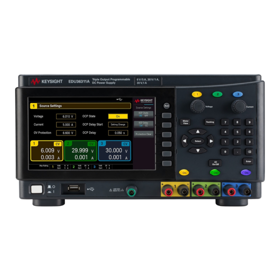
- Page 1 Service Guide EDU36311A Triple Output Programmable DC Power Supply...
-
Page 2: Table Of Contents
Measurement techniques Setup for most tests Constant Voltage (CV) verification CV load and line regulation Constant Current (CC) verification Test Record Forms Test record form - Keysight EDU36311A Calibration Adjustment Procedures Closed–case electronic calibration Calibration interval Calibration adjustment process Calibration security... - Page 3 Save the calibration data Keysight EDU36311A Service Guide...
-
Page 4: Notices
No part of this manual may be reproduced in any form or by any means (including electronic storage and retrieval or translation into a foreign language) without prior agreement and written consent from Keysight Technologies as governed by United States and international copyright laws. -
Page 5: U.s. Government Rights
FAR and the DFARS and are set forth specifically in writing elsewhere in the EULA. Keysight shall be under no obligation to update, revise or otherwise modify the Software. With respect to any technical data as defined by FAR 2.101, pursuant to FAR 12.211 and 27.404.2 and DFARS 227.7102, the U.S. -
Page 6: Safety Information
A WARNING notice denotes a hazard. It calls attention to an operating procedure, practice, or the like that, if not correctly per- formed or adhered to, could result in personal injury or death. Do not proceed beyond a WARNING notice until the indicated con- ditions are fully understood and met. Keysight EDU36311A Service Guide... -
Page 7: Service And Maintenance
To Replace the Power-Line Fuse User Replaceable Parts Battery Replacement Disassembly This chapter provides the specifications and service information on cleaning, troubleshooting, repair, and replaceable parts of the EDU36311A. This chapter also explains how to assemble and disassemble the EDU36311A. Keysight EDU36311A Service Guide... -
Page 8: Specifications And Characteristics
Types of service available If your instrument fails during the warranty period, Keysight Technologies will repair or replace it under the terms of your warranty. After your warranty expires, Keysight offers repair services at competitive prices. You also have the option to purchase a service contract that extends the coverage after the standard warranty expires. -
Page 9: Troubleshooting
If required, contact a Keysight Technologies Sales and Service office to arrange for proper cleaning to ensure that safety features and performance are maintained. Electrostatic Discharge (ESD) precautions Almost all electrical components can be damaged by electrostatic discharge (ESD) during handling. Component damage can occur at electrostatic discharge voltages as low as 50 V. -
Page 10: Replacing The Power-Line Fuse
Replacing the Power-Line Fuse Refer to EDU36311A User's Guide for details. User Replaceable Parts You can find the instrument support part list at Keysight's Test & Measurement Parts Catalog http://www.keysight.com/find/parts. Battery Replacement SHOCK HAZARD Only qualified, service-trained personnel who are aware of the hazards involved should remove instrument covers. - Page 11 (see red circle below) and push down on the opposite end of the battery (see red arrow below) to seat the bat- tery. 5. Reassemble the front panel when finished. 6. Reset the date and time. Properly dispose of the old battery in accordance with local laws and regulations. Keysight EDU36311A Service Guide...
-
Page 12: Disassembly
Then, remove the rubber foot from the instrument. Remove two screws (M3x6) with T10 Torx driver that holds the front panel and the chassis cover. On the rear panel, remove three screws (M3x6) with T10 Torx driver. Pull out the chassis cover. Keysight EDU36311A Service Guide... - Page 13 Remove six screws (M3x6) from the metal handle support. Remove three screws (M3x6) from the rear panel board. Lift up the metal handle support. Open the clip and remove the rear panel board from the metal handle support. Keysight EDU36311A Service Guide...
- Page 14 See image (B). Pull out the front panel. Disconnect all the cables from the main board. The front panel is removed. To install back the front panel, perform the above steps in reverse order. Keysight EDU36311A Service Guide...
-
Page 15: Removing/Installing The Knob
Insert the stainless steel belt into the PVC strap. Insert the stainless steel gaskets to both side of the stainless steel belt. Cover both side with the plastic cap. Secure both side of the strap handle with two screws (M5x10) using T25 Torx driver. Keysight EDU36311A Service Guide... -
Page 16: Verification And Adjustments
Test Record Forms Calibration Adjustment Procedures This chapter contains the performance verification procedures which verify that the EDU36311A is operating within its published specifications. This chapter also provides information on adjustments performed after a performance verification fails. Keysight EDU36311A Service Guide... -
Page 17: Performance Verification
150 V, 5 A minimum, with transient capability and a slew rate of Keysight N3300A mainframe, with 833 kA/s or better. N330xA modules LAN / USB controller PC with Keysight Connection Expert loaded Oscilloscope Sensitivity: 1 mV; Bandwidth Limit: 20 MHz Probe: 1:1 with RF Keysight DSOX1202A oscilloscope or... -
Page 18: Measurement Techniques
This setup is used for most tests and it requires the DMM, electronic load, and power supply being verified. Some wire is also required for connection between instruments. A LAN or USB cable is needed for readback data. The Keysight EDU36311A Service Guide... -
Page 19: Constant Voltage (Cv) Verification
SCPI MEAS:VOLT? (@<channel>) This is an example for 6 V, 5 A output. 10. Record the voltage returned by the SCPI command query via Keysight Connection Expert, and verify whether it is within the limits calculated. Keysight EDU36311A Service Guide... -
Page 20: Cv Load And Line Regulation
8. Take the difference between the DMM readings in steps 6 and 7 that is the CV load regulation (V load – V noload ). The difference of the readings during the immediate change should be within the specification limits. Keysight EDU36311A Service Guide... - Page 21 10. Take the difference between the DMM readings in steps 8 and 9 that is the CV line regulation (V lowline – V high- line ). The difference of the readings during the immediate change should be within the limit calculated from the specification. Keysight EDU36311A Service Guide...
- Page 22 7. Adjust the oscilloscope to display transients as shown below. Note that the pulse width (t2-t1) of the transient at the voltage settling band, for example 15 mV for Output 1 from the base line is no more than 50 µs. Keysight EDU36311A Service Guide...
- Page 23 The oscilloscope cursors AX and BX represent t1 and t2. The oscilloscope green trace and yellow trace represent output current and output voltage trace. 8. Transient response specification is met when the voltage recovers within 50 μs. Keysight EDU36311A Service Guide...
-
Page 24: Constant Current (Cc) Verification
SCPI MEAS:CURR? (@<channel>) This is an example for 6 V, 5 A output. 11. Record the current returned by the SCPI command query via Keysight Connection Expert, and verify whether it is within the limits calculated. Keysight EDU36311A Service Guide... - Page 25 8. Take the difference between the current readings in steps 6 and 7 is the load regulation current (I load – I short ). The difference of the readings during the immediate change should be within the specification limits. Keysight EDU36311A Service Guide...
- Page 26 9. Take the difference between the DMM readings in steps 7 and 8 is the CC line regulation (I lowline – I highline ). The difference of the readings during the immediate change should be within the specification limits. Keysight EDU36311A Service Guide...
-
Page 27: Test Record Forms
Test Record Forms Test record form - Keysight EDU36311A Test record form - Keysight EDU36311A EDU36311A Report Number ____________ Date ______________ Description Outputs Lower limit Result Upper limit Constant Voltage Tests Voltage Programming Zero Voltage Output (V 0 ) Output 1 -0.005 V... - Page 28 Current Programming & Readback, Maximum Current (I max ) 5 A, 6 V 1 A, 30 V 1 A, 30 V CC Load Regulation and Line Regulation 5 A, 6 V 1 A, 30 V 1 A, 30 V Keysight EDU36311A Service Guide...
-
Page 29: Calibration Adjustment Procedures
The default passcode is EDU36311A. The security code cannot be changed by a power cycle or *RST. You can enter a passcode of up to 12 characters. The first character must be a letter (A-Z), remaining may contains letters, numbers (0-9), or underscore "_". -
Page 30: Calibration Count
CAL:COUNt? query, and the calibration count is not change by a power cycle or *RST. If Auto Save is enabled, the count increments whenever a calibration point is calibrated successfully. To avoid double counting, do not manually save the count with Auto Save enabled. Keysight EDU36311A Service Guide... -
Page 31: Calibration Message
To begin the calibration procedure, you must enter the calibration state. Step Front Panel SCPI Press Utilities > Instr. Setup > Calibration. Use Keyboard to enter the security passcode (default passcode is EDU36311A) and CAL:SEC:STAT 0, <code> press Apply. Press State Login to enter the calibration page. - Page 32 After completing the Voltage and Current calibrations, save the calibration data before exiting the calibration state, or simply exit the calibration state if Auto Save is on. To save the CAL data: CAL:SAVE To enable the CAL Auto Save: CAL:ASAVE ON To exit CAL State: CAL:SEC:STAT 1, <code> Keysight EDU36311A Service Guide...
- Page 33 This information is subject to change without notice. © Keysight Technologies 2021 Edition 1, January 2021 Printed in Malaysia EDU36311-90014 www.keysight.com...
Need help?
Do you have a question about the EDU36311A and is the answer not in the manual?
Questions and answers