Table of Contents
Advertisement
Advertisement
Table of Contents

Related Manuals for Keysight E36300 Series


Summary of Contents for Keysight E36300 Series
- Page 1 User’s Guide E36300 Series Programmable DC Power Supplies...
-
Page 2: Table Of Contents
Interface Connections Installing the optional GPIB interface (E36312A and E36313A only) Rack mounting the instrument Remote Interface Configuration Keysight IO Libraries Suite GPIB configuration LAN configuration More about IP addresses and dot notation Remote Control Web interface Keysight E36300 Series User's Guide... - Page 3 Step 4 – Turn on Output 1, start the sequencing and log the data. Step 5 – Export the data Data logger view Adjusting the waveform display Data logger properties and waveform settings Save the datalog Keysight E36300 Series User's Guide...
- Page 4 GPIB (optional and applicable to E36312A and E36313A only) Utilities Menu - Test / Setup Calibration Self Test User Settings Low Range Help Utilities Menu - Error Utilities Menu - Manage Files Action Browse File Name Characteristics and Specifications Keysight E36300 Series User's Guide...
-
Page 5: Notices
No part of this manual may be reproduced in any form or by any means (including electronic storage and retrieval or translation into a foreign language) without prior agreement and written consent from Keysight Technologies as governed by United States and international copyright laws. -
Page 6: U.s. Government Rights
FAR and the DFARS and are set forth specifically in writing elsewhere in the EULA. Keysight shall be under no obligation to update, revise or otherwise modify the Software. With respect to any technical data as defined by FAR 2.101, pursuant to FAR 12.211 and 27.404.2 and DFARS 227.7102, the U.S. -
Page 7: Safety Information
A WARNING notice denotes a hazard. It calls attention to an operating procedure, practice, or the like that, if not correctly per- formed or adhered to, could result in personal injury or death. Do not proceed beyond a WARNING notice until the indicated con- ditions are fully understood and met. Keysight E36300 Series User's Guide... -
Page 8: Safety And Regulatory Information
Return the instrument to a Keysight Technologies Sales and Service Office for service and repair to ensure that safety features are maintained. To contact Keysight for sales and technical support, refer to the support links on the following Keysight website: www.keysight.com/find/assist... -
Page 9: Safety Symbols
Do not proceed beyond CAUTION sign until the indicated conditions are fully understood and met. The NOTE sign denotes important information. It calls attention to a procedure, practice, condition or the like, which is essential to highlight. Keysight E36300 Series User's Guide... -
Page 10: Regulatory Markings
– 사용자 안내문은 “업무용 방송통신기자재”에만 적용한다. Safety and EMC Requirements This power supply is designed to comply with the following safety and EMC (Electromagnetic Compatibility) requirements: – Low Voltage Directive 2014/35/EU – EMC Directive 2014/30/EU Keysight E36300 Series User's Guide... -
Page 11: Environmental Conditions
Environmental Conditions The E36300 Series is designed for indoor use and in an area with low condensation. The table below shows the general environmental requirements for this instrument. Environmental condition Requirement Temperature Operating condition: 0 °C to 40 °C Storage condition: –20 °C to 70 °C Humidity Operating condition: Up to 80% RH at 40 °C (non-condensing) - Page 12 Keysight E36300 Series User's Guide...
-
Page 13: Getting Started
Options and Fuse Information Programming Ranges Installation Remote Interface Configuration Remote Control Using the Built-in Help System Firmware Update Front Panel Menu Reference This chapter gets you started with the E36300 Series programmable DC power supply. Keysight E36300 Series User's Guide... -
Page 14: Product Introduction
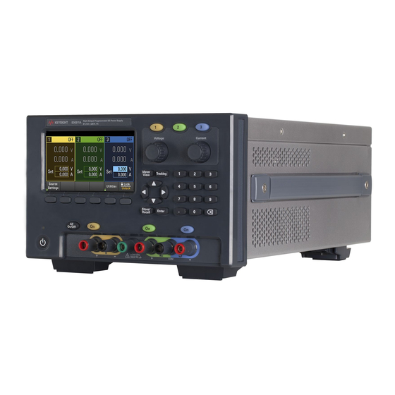
Product Introduction The Keysight E36300 Series is a series of three DC bench and system power supplies. All three models include: – Three outputs: – 6 V/5 A, +25 V/1 A, -25 V/1 A (E36311A) – 6 V/5 A, +25 V/1 A, +25 V/1 A (E36312A) –... -
Page 15: Front Panel At A Glance
– Enters numeric values. Press [Enter] key to complete the entry. – Deletes the values entered into the dialog using the back key. Output On key Turns individual outputs On or Off; outputs are on when the key is lit. Output terminals Keysight E36300 Series User's Guide... - Page 16 Turns all outputs On and Off according to the specified turn-on and turn-off delays. Softkeys Accesses the soft front panel menu. USB port Allows an external USB drive to be connected to the instrument. (E36312A and E36313A only) Keysight E36300 Series User's Guide...
-
Page 17: Rear Panel At A Glance
Digital I/O terminal port (E36312A and E36313A only) LAN port (E36312A and E36313A only) USB port GPIB port (E36312A and E36313A Option GPIB only ) AC inlet AC selector fuse-holder assembly AC selector Fan ventilation hole Keysight E36300 Series User's Guide... -
Page 18: Meter View
: The instrument is not connected to LAN. : The instrument is connected to USB. (blinking): The LAN connection is at fault. : The instrument is connected to LAN. (blinking): The instrument is under identification mode via remote interface. Keysight E36300 Series User's Guide... - Page 19 Ratings and protection Displays the present over-voltage protection (OVP) setting and whether over-current protection (OCP) is on or off. Output delay Displays the OCP, Output On and Output Off delay values. Soft front panel menu Keysight E36300 Series User's Guide...
-
Page 20: Data Logger View
Time/Div Indicates the horizontal time-base setting. Offset time Indicates the time that the right gridline is offset or away from the end of the data log. Grid time Displays the time on the gridline Keysight E36300 Series User's Guide... -
Page 21: Dimension Diagram
Before disconnecting cables and cords from the instrument, turn the instrument off using the front-panel On/Standby key and disconnect from the supply source by unplugging the detachable power cord. Keysight E36300 Series User's Guide... -
Page 22: Prepare Instrument For Use
Initial inspection When you receive your power supply, inspect it for any obvious damage that may have occurred during shipment. If there is damage, notify the shipping carrier and nearest Keysight Sales and Support Office immediately. Refer to www.keysight.com/find/assist. Until you have checked out the power supply, save the shipping carton and packing materials in case the unit has to be returned. -
Page 23: Options And Fuse Information
For example, to select 230 V, slide the left switch to the left and the right switch to the right, as illustrated in the diagram below the switches. To select 115 V, slide both switches to the right, and to select 100 V, slide the two switches towards each other. Keysight E36300 Series User's Guide... - Page 24 To configure the correct fuse, follow the three steps shown below: Pull the fuse holder out of the Remove and insert the proper Re-insert the fuse holder into the power supply. fuse into the fuse holder. power supply. Keysight E36300 Series User's Guide...
-
Page 25: Programming Ranges
DEFault (*RST) 10 A Note: 1. Applicable for E36311A or when SCPI ID is set to E3631A (E36312A and E36313A). In normal operation, the E36312A and E36313A will output as +25 V. 2. Applicable for E36313A. Keysight E36300 Series User's Guide... -
Page 26: Installation
Connect the power cord to the AC inlet connector on the rear of the unit. If the wrong power cord was shipped with your unit, contact your nearest Keysight Sales and Support Office. Removing the power cord will disconnect AC input power to the unit. -
Page 27: Connecting The Outputs
Secure the 12 A connector by tightening the locking screws. A chassis ground binding post is located next to the fan ventilation hole for ground connections. Part number information for the connector kit is provided under Standard Shipped Items. Keysight E36300 Series User's Guide... - Page 28 Connect each load to the distribution terminals separately. For multiple load application, all loads should either be connected to the front panel binding post or rear panel output. Keysight E36300 Series User's Guide...
- Page 29 Front panel Rear panel (E36312A and E36313A only) Keysight E36300 Series User's Guide...
-
Page 30: Parallel And Series Connections (E36312A And E36313A Only)
Rear panel The figure on the left illustrates 2-wire sensing. If voltage drop in the load leads is a concern, the figure on the right shows how to connect the sense leads directly at the load. Keysight E36300 Series User's Guide... - Page 31 Front panel Rear panel If voltage drop in the load leads is a concern, connect the sense leads of output 2 and output 3 for 4-wire sensing as shown in the figure on the right. Keysight E36300 Series User's Guide...
-
Page 32: 4-Wire Sense Connection (E36312A And E36313A Only)
Try to keep the sense lead resistance less than about 0.5 Ω per lead (this requires 20 AWG or heavier for a 50 foot length). After turning the unit on, activate 4-wire remote voltage sensing by pressing Source Settings > Sense 4w . Refer to Specifying 2-Wire or 4-Wire Sense. Keysight E36300 Series User's Guide... - Page 33 Twist the sense leads or use a ribbon cable to minimize the pickup of external noise. In extremely noisy environments it may be necessary to shield the sense leads. Ground the shield at the power supply end only; do not use the shield as one of the sensing conductors. Keysight E36300 Series User's Guide...
-
Page 34: Interface Connections
Remote Interface Configuration. If you have not already done so, install the Keysight IO Libraries Suite, which can be found at www.key- sight.com/find/iolib. For detailed information about interface connections, refer to the Keysight Tech- nologies USB/LAN/GPIB Interfaces Connectivity Guide included with the Keysight IO Libraries Suite. - Page 35 LAN settings from the front panel of the instrument. 2. Use the Connection Expert utility of the Keysight IO Libraries Suite to add the power supply and verify a connection. To add the instrument, you can request the Connection Expert to discover the instrument. If the instrument cannot be found, add the instrument using its hostname or IP address.
- Page 36 LAN settings from the front panel of the instrument. 3. Use the Connection Expert utility of the Keysight IO Libraries Suite to add the power supply and verify a connection. To add the instrument, you can request the Connection Expert to discover the instrument. If the instrument cannot be found, add the instrument using its hostname or IP address.
- Page 37 Positive polarity is selected, a logical true signal is a voltage high at the pin. When Negative polarity is selected, a logical true signal is a voltage low at the pin. For more information on configuring the digital port functions, refer to Using the Digital Control Port. Keysight E36300 Series User's Guide...
-
Page 38: Installing The Optional Gpib Interface (E36312A And E36313A Only)
Use the screw that was removed earlier to secure the GPIB plate in place. This concludes the GPIB installation procedure. Keysight E36300 Series User's Guide... -
Page 39: Rack Mounting The Instrument
To rack mount two instruments side-by-side, order lock-link kit (5061-8769). Be sure to use the support rails in the rack cabinet. Front handle kit (5063-1559) Rackmount kit without handles (5063-1564) Rackmount kit with handles (5063-1575) For instrument with previously supplied handles, order flange kit (5063-1569). Keysight E36300 Series User's Guide... -
Page 40: Remote Interface Configuration
IP address every time it connects to the network. Keysight IO Libraries Suite Ensure that the Keysight IO Libraries Suite is installed before you proceed for the remote interface con- figuration. Keysight IO Libraries Suite is a collection of free instrument control software that automatically discovers instruments and allows you to control instruments over LAN, USB, GPIB, RS-232, and other interfaces. -
Page 41: Lan Configuration
If the settings are different, it is because the network has automatically assigned its own settings. Restarting the LAN Press Utilities > I/O Config > LAN Status > LAN Restart restarts the networking using ALL current LAN settings. LAN restart does not clears the Web interface password. Keysight E36300 Series User's Guide... - Page 42 – This setting is non-volatile; it will not be changed by power cycling or *RST or SYSTem:PRESet. 1. Press Utilities > I/O Config > LAN Settings > DHCP On to use DHCP to automatically assign an IP address. 2. Press Back . You will be prompted by the below message. Keysight E36300 Series User's Guide...
- Page 43 2. Select Subnet Mask field using the navigation keys. Set the desired subnet mask address and press Back . (Example: 255.255.0.0) 3. Press Yes to save the setting. 4. Press No to cancel all the changes and exit without saving. Keysight E36300 Series User's Guide...
- Page 44 4. Set the desired primary and secondary address and press Back . 5. Select mDNS Service field using the navigation keys. 6. Press Yes to save the setting. 7. Press No to cancel all the changes and exit without saving. Keysight E36300 Series User's Guide...
- Page 45 The mDNS service name is registered with the selected naming service. Each power supply is shipped with a default service name with the format: Keysight-modelnumberserialnumber, where modelnumber is the power supply’s 7-character model number (e.g. E36312A), and serialnumber is the last five characters of the 10-character power supply serial number located on the label on the top of the unit (e.g.
-
Page 46: More About Ip Addresses And Dot Notation
"192.168.020.011" is equivalent to decimal "192.168.16.9" because ".020" is 16 expressed in octal, and ".011" (octal) is "9" (base 10). To avoid confusion, use only decimal values from 0 to 255, with no leading zeros. Keysight E36300 Series User's Guide... -
Page 47: Remote Control
Check the checkbox below the picture of the instrument to enable an indicator on the instrument's front panel. This is helpful if you have several E36300 Series instruments and you wish to identify the one to which you are connected. -
Page 48: Technical Connection Details
Port number 80, URL http://<IP address>/ USB0::0x2A8D::<Prod ID>::<Serial Number>::0::INSTR Example: USB0::0x2A8D::0x0902::MY55160003::0::INSTR The vendor ID: 0x2A8D, the product ID is 0x0902, and the instrument serial number is MY55160003. The product ID varies by model: 0x1002 (E36311A), 0x1102 (E36312A), 0x1202 (E36313A). Keysight E36300 Series User's Guide... -
Page 49: Use The Built-In Help System
Press Utilities > Test / Setup > Help to view the list of help topics. Press the arrow softkeys or use the front panel arrow keys to highlight the desired topic. Then press Select . Keysight E36300 Series User's Guide... - Page 50 Russian. To select the local language, press Utilities > Test / Setup > User Settings > Display Options > Help Lang . Then select the desired language. The menu softkey labels and status line messages are not trans- lated. Keysight E36300 Series User's Guide...
-
Page 51: Firmware Update
Otherwise, download the firmware update utility and a ZIP file of the firmware. Detailed firmware update instructions are located on the download page. Keysight E36300 Series User's Guide... -
Page 52: Front Panel Menu Reference
Creates, copies, deletes, and renames files and folders on a USB drive attached to the front panel. Also allows you to capture the current screen to either a bitmap (*.bmp) or portable network graphics (*.png) file. Lock|Unlock Locks and unlocks the display. Keysight E36300 Series User's Guide... -
Page 53: General Operating Information
The E36300 Series uses colors and numbers to let you easily identify information related to specific outputs. For example, all the configuration and display items related to output 1 are shown in the same color as the output selection key. Keysight E36300 Series User's Guide... -
Page 54: Turning The Unit On
A power-on self-test occurs automatically when you turn the unit on. This assures you that the instrument is operational. If self-test fails, or if other operating problems occur with your instrument, the front panel error indicator (!Err) appears at the upper top of the display. Keysight E36300 Series User's Guide... -
Page 55: View The Error Log
– Except for self-test errors, errors are cleared when exiting the Error Log menu or when cycling power. If you suspect that there is a problem with the power supply, refer to the Troubleshooting section in the Service Guide. Keysight E36300 Series User's Guide... -
Page 56: Controlling The Outputs
Voltage or Current fields. Then enter the voltage and current values with the numeric keys. You can use the Voltage and Current knobs to adjust the values in the Voltage and Current fields. Press [Enter] to enter the value. Press Back to return to the meter-view display. Keysight E36300 Series User's Guide... -
Page 57: Step 3 - Enable The Output
Step 4 - View the output voltage and current Press [Meter View] to view the output voltage and current. When an output is enabled, the front panel meters continuously measure and display the output voltage and current. Keysight E36300 Series User's Guide... -
Page 58: Constant Voltage And Constant Current
To set only output 1 to 5 V and 1 A: APPL Ch1 5, 1 To enable only output 1: OUTP ON,(@1) To enable output 1 and output 3: OUTP ON,(@1,3) To measure the output voltage and current of output 1: MEAS:VOLT? (@1) MEAS:CURR? (@1) Keysight E36300 Series User's Guide... -
Page 59: Using The Protection Function
To set the over-voltage protection, enter an over-voltage value in the OV Protection field. For E36311A or when SCPI ID is set to E3631A, you can program a negative over-voltage protection level which will disable the output when negative voltages are detected. Keysight E36300 Series User's Guide... - Page 60 OCP delay time has expired and if the CC mode persists, the output will shut down. You can specify the OCP delay start timer through: – CC Transition: delay timer start at any transition of the output into CC mode. Press OCP Start CC . Keysight E36300 Series User's Guide...
-
Page 61: Clears And Ovp And Ocp Event
To set the over-current protection delay time for output 1 at 3 seconds: CURR:PROT:DEL 3 (@1) To set the over-current protection delay timer start for output 1 to CC transition: CURR:PROT:DEL:STAR CCTR (@1) To clear protection for output 1: OUTP:PROT:CLE (@1) Keysight E36300 Series User's Guide... -
Page 62: Specifying 2-Wire Or 4-Wire Sense (E36312A And E36313A Only)
Using the Tracking Operation The E36300 Series provides 0 to ±25 V tracking outputs. In the track mode, two voltages from Output 2 and Output 3 track each other for convenience in varying the symmetrical voltages needed by operational amplifiers and other circuits using balanced positive and negative inputs. -
Page 63: Configuring The Output Turn On Turn Off Sequence (E36312A And E36313A Only)
– Press Coup CH 2 to toggle between Off and On in order to turn off or on the coupling for Output 2. – Press Coup CH 3 to toggle between Off and On in order to turn off or on the coupling for Output 3 Keysight E36300 Series User's Guide... -
Page 64: Step 4 - Use The All Outputs On And Off Keys
OUTP:DEL:RISE 0.02,(@2) OUTP:DEL:RISE 0.03,(@3) OUTP:DEL:FALL 0.04,(@1) OUTP:DEL:FALL 0.03,(@2) OUTP:DEL:FALL 0.02,(@3) To only include outputs 1 and 2 in a sequence : OUTP:COUP:CHAN CH1,CH2 To turn on two coupled outputs in a sequence: OUTP ON (@1:2) Keysight E36300 Series User's Guide... -
Page 65: Specifying The Operation Mode (E36312A And E36313A Only)
For output connection in Auto-Series and Auto-Parallel mode, see Parallel and Series Connections for details. From the remote interface: To enable Auto-Series mode: OUT:PAIR SER To enable Auto-Parallel mode: OUT:PAIR PAR To enable Tracking mode: OUTP:TRAC ON Keysight E36300 Series User's Guide... -
Page 66: Using The Digital Control Port (E36312A And E36313A Only)
The digital I/O pin can be used to control both relay circuits as well as digital interface circuits. The figure above illustrates typical relay circuits as well as digital interface circuit connections using the digital I/O functions. Keysight E36300 Series User's Guide... - Page 67 To configure the pin polarity to positive for pins 1 through 3: DIG:PIN 1:POL POS DIG:PIN 2:POL POS DIG:PIN 3:POL POS To send a binary weighted value to configure pins 1 through 3 as “111”: DIG:OUTP:DATA 7 Keysight E36300 Series User's Guide...
-
Page 68: Digital Input
The polarity of pin 1 can also be configured. Note that the fault output signal remains latched until the fault condition is removed and the protection circuit is cleared. Pin 2's selected function is ignored. Pin 2 should be connected to the ground of the external circuit. Keysight E36300 Series User's Guide... -
Page 69: Inhibit Input
Alternatively, you can configure Pin 3 as a remote inhibit input by pressing Output Settings > Output Inhibit > DIO Pin 3 INH . In this setting, the polarity is set to Positive by default. Keysight E36300 Series User's Guide... -
Page 70: Fault/Inhibit System Protection
Note that when using the Fault/Inhibit signals in this manner, both signals must be set to the same polarity. Keysight E36300 Series User's Guide... -
Page 71: Trigger Input
4. Configure the polarity for each of the pin. Press Polarity Pos to select Positive and Polarity Neg to select Negative. Select and program the remaining pins in the same manner. Keysight E36300 Series User's Guide... -
Page 72: Trigger Output
DIG:PIN1:POL NEG Output couple controls This function lets you connect multiple Keysight E36300 Series power supplies together and synchronize the output on/off sequence across units. Each power supply that will be synchronized must have at least one coupled output. Keysight E36300 Series User's Guide... - Page 73 3. Connect and configure the digital connector pins of the synchronized power supplies as described in this sec- tion. All synchronized E36300 Series power supplies must have the same firmware revision. Only pins 1 though 3 can be configured as synchronization pins. You cannot configure more than one On Couple and one Off Couple pin per power supply.
- Page 74 On and Off keys, the Web server, and to SCPI commands. Turning the outputs on or off using the front panel [All On/Off] key will cause all coupled outputs as well as non- coupled outputs on that power supply to turn on or off. Keysight E36300 Series User's Guide...
-
Page 75: Using The Output List (E36312A And E36313A Only)
Continue to add steps until your sequence is complete. Use the navigation keys to move through the list. Press Delete if you want to delete the selected step or press Clear All if you want to remove all steps from the list. Keysight E36300 Series User's Guide... -
Page 76: Step 2 - Configure The Output Sequence
Enables check box to set which step will generate a trigger-out signal at the end of the step (EOST). For additional settings, press Properties to open the Output LIST Properties window. Configure the Output LIST accordingly. Refer to the below table for details. Keysight E36300 Series User's Guide... - Page 77 Fix (Fixed) Keeps the output at its immediate value. Stp (Step) Steps the output to the triggered level when a trigger occurs Lst (List) Causes the output to follow the list values when a trigger occurs. Keysight E36300 Series User's Guide...
-
Page 78: Step 3 - Run The Output Sequence List
– Press the color-coded [On] key to enable the selected output. – Press Run to start the list operation. To abort the operation, press Stopped . – Press Back to exit and return to the previous menu. Keysight E36300 Series User's Guide... - Page 79 To set the current mode of output 1 to List: CURR:MODE LIST, (@1) To set the trigger source of output 1 to Key/Immediate: TRIG:SOUR IMM, (@1) To enable output 1: OUTP ON, (@1) To initiate and run the list: INIT (@1) Keysight E36300 Series User's Guide...
-
Page 80: Using The Data Logger Function (E36312A And E36313A Only)
Step 2: 3 V; 0.1 A; 1 s Step 3: 4 V; 0.1 A; 1 s Step 4: 5 V; 0.1 A; 1 s Repeat Count: 5 Pace: Dwell Voltage Mode: List Current Mode: List Trigger Source: List Run/Stop Key Keysight E36300 Series User's Guide... -
Page 81: Step 2 - Configure The Data Logger Traces
V1 trace to the bottom of the grid. Traces are color coded according to output. The ground symbol on the right side of the display indicates the ground reference of the trace. Keysight E36300 Series User's Guide... -
Page 82: Step 3 - Configure The Data Logger Properties
A message will indicate that the logged data has been saved in a file named default.dlog. If you wish to save the data under a different filename, you must specify the filename before the data logger runs. Press File Name located at the data logger Properties menu to specify a filename. Keysight E36300 Series User's Guide... -
Page 83: Step 5 - Export The Data
To program output sequence of five steps on output 1: LIST:VOLT 1,2,3,4,5, (@1) LIST:CURR 0.1,0.1,0.1,0.1,0.1, (@1) LIST:DWEL 1,1,1,1,1, (@1) LIST:COUNT 5, (@1) LIST:STEP AUTO, (@1) VOLT:MODE LIST, (@1) CURR:MODE LIST, (@1) To initiate the trigger system: TRIG:SOUR BUS INIT (@1) Keysight E36300 Series User's Guide... -
Page 84: Data Logger View
The black part represents the data that is not visible. Time/Div Identifies the horizontal time-base setting. This can be adjusted using the Horizontal Time/Div + and Time/Div – in Waveform Settings. Keysight E36300 Series User's Guide... -
Page 85: Adjusting The Waveform Display
Press Waveform Settings to access the waveform settings menu. Press the first softkey to toggle between Vertical and Horizontal to display the vertical and horizontal settings menu. The Vertical settings menu will change accordingly to the selected trace. Keysight E36300 Series User's Guide... -
Page 86: Data Logger Properties And Waveform Settings
Specified in time/division on the x axis. Applies to ALL traces. Offset Configures the waveform location (right or left) of the horizontal offset reference. The trig- ger point is indicated by the solid arrow . Keysight E36300 Series User's Guide... - Page 87 Sets to enable or disable the Log Min/Max checkbox. Enabling the checkbox will log the minimum and maximum values to the data log file. With Log Min/Max checked, the resulting file size will triple. Default is Off. Action required: Press Lg MinMax to toggle between Off and On. Keysight E36300 Series User's Guide...
-
Page 88: Save The Datalog
Data Logger runs. If you do not specify a filename, the data will be logged to default.dlog, which is overwritten each time the Data Logger runs. Enable the Append date and time to file name checkbox to include timestamp information on the filename. Keysight E36300 Series User's Guide... - Page 89 Press Export File to export the data that is currently in the instrument's datalog viewer to file. The exported data is in .csv format. For details on how to specify the save location and filename, refer to Save the Data Log. Keysight E36300 Series User's Guide...
- Page 90 Press Load File to load the logged data to the instrument. You can load both binary files and data files in .csv format. Press Browse to browse and select file from the directory. Press Select to select the file or Cancel to abort. Press Load to load the file. Keysight E36300 Series User's Guide...
-
Page 91: Locking/Unlocking The Front Panel
Press [Meter View] for more than three seconds to capture a screen. The screen that was active will be saved to the USB flash storage connected to the front USB port. To configure the screen capture storing path, refer to Utilities Menu - Manage Files for details. Keysight E36300 Series User's Guide... -
Page 92: Enabling The E3631A Mode
Enabling the E3631A Mode The E3631A mode allows you to change the programmatic identity of the E36300 Series back to E3631A for code compatibility and enables it to works like the E3631A in existing applications. Press Utilities > Test / Setup > User Settings > SCPI ID . -
Page 93: Utilities Menu
– Operation mode (Independent, Series, Parallel or Track) – Output on/off sequencing – Output LIST settings – Trigger setttings – Digital I/O output data and bus setting – Data logger trigger source 1. Applicable for E36312A and E36313A Only Keysight E36300 Series User's Guide... -
Page 94: Store Settings
Selects the state to store state settings. Set PwrOn Yes, No Selects to enable or disable the 'Set this as power-on state' checkbox. Enabling the checkbox will load the selected stored state at power-up. Store Stores the state. Keysight E36300 Series User's Guide... - Page 95 Allows you to browse and specify the location where the folder will be placed. Folder Name Specifies the folder name. Use the virtual keyboard to enter your desired folder name. Create Folder Creates a new folder in the specified location. Keysight E36300 Series User's Guide...
-
Page 96: Recall Settings
– Internal:\ specifies the instrument's internal memory. – External:\ specifies the USB port on the front panel. Browse Allows you to browse and specify the state file in the external memory to recall from. Recall Recall the state. Keysight E36300 Series User's Guide... -
Page 97: Power On Setting
Power On selects the state that will be loaded at power-up. This can be either the factory default state (Default), or user-defined states (State 0 to State 9). Press Set Power On to save the setting. Set to Defaults Set to Defaults loads the instrument's factory default state. Keysight E36300 Series User's Guide... -
Page 98: Utilities Menu - I/O Configuration
LAN Restart restarts the networking using its current LAN settings. LAN restart does not clears the user-defined Web Interface password. LAN Settings LAN Settings opens the window shown below. Set to Defaults resets the LAN settings to their factory default values. Keysight E36300 Series User's Guide... -
Page 99: Digital Io (E36312A And E36313A Only)
GPIB (optional and applicable to E36312A and E36313A only) GPIB allows you to set the GPIB address to a value from 0 to 30. After changing the address, cycle instrument power for the change to take effect. Keysight E36300 Series User's Guide... -
Page 100: Utilities Menu - Test / Setup
Reset to Factory returns the settings to factory default settings. Pressing this key sanitizes all user-accessible instrument memory except calibration constants and reboots the instrument. Self Test Self Test verifies proper instrument operation. Refer to "Self-Test Procedures" in the Service Guide for details. Keysight E36300 Series User's Guide... -
Page 101: User Settings
Date / Time sets the instrument's real-time clock, which always uses a 24-hour format (00:00:00 to 23:59:59). There is no automatic setting of the date and time, such as to adjust for daylight savings time. Keysight E36300 Series User's Guide... -
Page 102: Low Range
Help allows you to view the quick reference help topic. Use the arrow softkeys or front panel navigation keys to navigate the desired topic. Press Select to view the help content. About allows you to view the instrument's model number, description and serial number. Keysight E36300 Series User's Guide... -
Page 103: Utilities Menu - Error
– Except for self-test errors, errors will be cleared after you have read them or after an instrument reset. If you suspect that there is a problem with the power supply, refer to "Troubleshooting" in the Service Guide. Keysight E36300 Series User's Guide... -
Page 104: Utilities Menu - Manage Files
Browse selects the file or folder upon which the action will be performed. Use the front-panel navigation keys to navigate through the list. The left and right arrows contract or expand a folder to hide or show its files. Press Select or Cancel to exit the browse window. Keysight E36300 Series User's Guide... -
Page 105: File Name
Previous Char and Next Char to move the cursor in the area where the name is entered. In the image below, there is no Next Char softkey because the cursor is at the end. Press Done or Cancel to finish. Keysight E36300 Series User's Guide... - Page 106 Keysight E36300 Series User's Guide...
-
Page 107: Characteristics And Specifications
Characteristics and Specifications For the characteristics and specifications of the E36300 Series programmable DC power supplies, refer to the datasheet at http://literature.cdn.keysight.com/litweb/pdf/5992-2124EN.pdf. Keysight E36300 Series User's Guide... - Page 108 This information is subject to change without notice. © Keysight Technologies 2017 Edition 1, April 30, 2017 Printed in Malaysia E36311-90001 www.keysight.com...
Need help?
Do you have a question about the E36300 Series and is the answer not in the manual?
Questions and answers