Nortel 5500 series Installation Manual
Hide thumbs
Also See for 5500 series:
- Cli manual (526 pages) ,
- Product support bulletin (2 pages) ,
- Installation manual (76 pages)
Table of Contents
Advertisement
Quick Links
Advertisement
Table of Contents

Related Manuals for Nortel 5500 series


Summary of Contents for Nortel 5500 series
- Page 1 Nortel Ethernet Routing Switch 5500 Series Installation NN47200-300 (217461-B)
-
Page 2: Restricted Rights Legend
In the interest of improving internal design, operational function, and/or reliability, Nortel Networks Inc. reserves the right to make changes to the products described in this document without notice. Nortel Networks Inc. does not assume any liability that may occur due to the use or application of the product(s) or circuit layout(s) described herein. - Page 3 CE marking statement (Europe only) EN 55 022 statements This is to certify that the Nortel Ethernet Routing Switch 5500 Series are shielded against the generation of radio interference in accordance with the application of Council Directive 89/336/EEC. Conformity is declared by the application of EN 55 022 Class A (CISPR 22).
-
Page 4: National Safety Statements Of Compliance
EN 60 950 statement This is to certify that the Nortel Ethernet Routing Switch 5500 Series are in compliance with the requirements of EN 60 950 in accordance with the Low Voltage Directive. Additional national differences for all European Union countries have been evaluated for compliance. - Page 5 (such as images, text, recordings or pictures) and related licensed materials including all whole or partial copies. Nortel Networks grants you a license to use the Software only in the country where you acquired the Software. You obtain no rights other than those granted to you under this License Agreement. You are responsible for the selection of the Software and for the installation of, use of, and results obtained from the Software.
- Page 6 227.7202 (for DoD entities). b) Customer may terminate the license at any time. Nortel Networks may terminate the license if Customer fails to comply with the terms and conditions of this license. In either event, upon termination, Customer must either return the Software to Nortel Networks or certify its destruction.
-
Page 7: Revision History
May 2005 New document for Software Release 4.2 July 2006 2.00 Updated document for Software Release 5.0 Nortel Ethernet Routing Switch 5500 Series Installation NN47200-300 2.00 Standard 5.0 7 July 2006 Copyright © 2005 - 2006, Nortel Networks Nortel Networks Confidential... - Page 8 8 Revision History Nortel Ethernet Routing Switch 5500 Series Installation NN47200-300 2.00 Standard 5.0 7 July 2006 Copyright © 2005 - 2006, Nortel Networks Nortel Networks Confidential...
-
Page 9: Table Of Contents
Environmental requirements 17 Package contents 19 Installing the Nortel Ethernet Routing Switch 5500 Series on a table or shelf 20 Installing the Nortel Ethernet Routing Switch 5500 Series in an equipment rack 22 Installing a Nortel Ethernet Routing Switch 5530-24TFD in a rear mounted configuration 23... - Page 10 Shared SFP transceiver port LED state indicators 40 XFP transceiver port LED indicators (5530-24TFD only) 40 Setting IP parameters for the Nortel Ethernet Routing Switch 5500 Series 41 Setting IP parameters using the console port and Console Menu 41 Setting IP Parameters using the console port and CLI 45...
-
Page 11: Preface
Preface This guide provides information and instructions on the proper installation of a 5500 Series Nortel Ethernet Routing Switch. Please consult any documentation included with the switch and the product release notes (see "Related publications" (page 12) on page 16) for any errata before beginning the installation procedure. -
Page 12: Related Publications
Transceiver Ports and two XFP Transceiver Ports. Related publications For more information about the management, configuration, and usage of the Nortel Ethernet Routing Switch 5500 Series, refer to the publications listed in " Nortel Ethernet Routing Switch 5500 Series Documentation" (page 12). - Page 13 - VLANs, Spanning Tree, and MultiLink Trunking Nortel Ethernet Instructions on the configuration of NN47200-503 Routing Switch 5500 IP routing protocols on 5500 Series Series Configuration switches. - IP Routing Protocols Nortel Ethernet Instructions on the configuration NN47200-504 Routing Switch 5500...
-
Page 14: Finding The Latest Updates On The Nortel Web Site
The content of this documentation was current at the time of release. To check for updates to the documentation and software for the Nortel Ethernet Routing Switch 5500 Series, use the links provided in the following table. Software Nortel Ethernet Routing Switch 5500 Series Software... -
Page 15: Installing The Nortel Ethernet Routing Switch
" Environmental requirements" (page 17) • " Package contents" (page 19) • " Installing the Nortel Ethernet Routing Switch 5500 Series on a table or shelf" (page 20) • " Installing the Nortel Ethernet Routing Switch 5500 Series in an equipment rack"... -
Page 16: Phone Dongle Part Number
Do not remove the wrist or ankle strap until the installation is complete. Preventing electrostatic damage in new cable installations With new cable installations, Nortel recommends that the use of an ESD discharge cable to reduce the potential for damage from static that can build up in cables. -
Page 17: Environmental Requirements
—End— Environmental requirements " Nortel Ethernet Routing Switch 5500 Series environmental requirements" (page 17) displays the environmental requirements for the individual switches in this series. Ensure that the area where the switch is installed and operated will meet these requirements. - Page 18 18 Installing the Nortel Ethernet Routing Switch Nortel Ether Nortel Ether Nortel Ethernet net Routing net Routing Routing Switch Switch 5510 Switch 5520 5530 temperature be extended can be to 14 to extended to 140 degrees 131 degrees Fahrenheit (-10...
-
Page 19: Package Contents
"Translations of safety messages" (page 61) on page 61. Package contents "Nortel Ethernet Routing Switch 5500 Series package contents" (page 19) illustrates the components that are provided with each switch in the 5500 Series. Should any components be missing, contact the vendor from which the switch was purchased. -
Page 20: Installing The Nortel Ethernet Routing Switch 5500 Series On A Table Or Shelf
For a translation of this statement, see "Translations of safety messages" (page 61) on page 61. To install a 5500 Series switch on a table or shelf, follow this procedure: Step Action Attach the provided rubber footpads at the locations noted in "Attaching the rubber footpads"... - Page 21 Installing the Nortel Ethernet Routing Switch 5500 Series on a table or shelf 21 Attaching the rubber footpads Set the switch on a table or shelf as illustrated in "Nortel Ethernet Routing Switch on a desk or shelf" (page 21). Allow at least 2 inches (5.1 centimeters) on each side for proper ventilation and at least 5...
-
Page 22: Installing The Nortel Ethernet Routing Switch 5500 Series In An Equipment Rack
"Translations of safety messages" (page 61) on page 61. To install a 5500 Series switch in an equipment rack, follow this procedure: Step Action Attach a bracket to each side of the switch using a #2 Phillips screwdriver as illustrated in "Attaching switch brackets"... -
Page 23: Installing A Nortel Ethernet Routing Switch 5530-24Tfd In A Rear Mounted Configuration
Installing a Nortel Ethernet Routing Switch 5530-24TFD in a rear mounted configuration 23 Mounting the switch —End— Installing a Nortel Ethernet Routing Switch 5530-24TFD in a rear mounted configuration The Nortel Ethernet Routing Switch 5530-24TFD now features the option of installing the switch in a rear mounted configuration. - Page 24 24 Installing the Nortel Ethernet Routing Switch Attaching rear mounted switch brackets Slide the switch into the rack as illustrated in "Rear mounted switch configuration" (page 24). Insert and tighten the rack-mount screws with a #2 Phillips screwdriver. Rear mounted switch configuration —End—...
-
Page 25: Cabling Requirements For The Nortel Ethernet Routing Switch 5500 Series
Installation and removal of SFP and XFP transceivers The following section outlines the installation and removal of SFP and XFP transceivers in the Nortel Ethernet Routing Switch 5500 Series. For complete coverage of SFP and XFP transceiver usage and designation,... -
Page 26: Removal Of Sfp And Xfp Transceivers
26 Installing the Nortel Ethernet Routing Switch Step Action Remove the transceiver from the protective packaging. Verify that the transceiver is the correct model for the network configuration. Grasp the transceiver between the thumb and forefinger. Insert the transceiver into the proper module on the switch. Apply a light pressure to the transceiver until it clicks and locks into position in the module. -
Page 27: Rj-45 Connector Pin Assignments
—End— RJ-45 connector pin assignments The following section outlines the connector pin assignments for the RJ-45 connectors in the Nortel Ethernet Routing Switch 5500 Series switches. Consult the appropriate section for specific information on an individual switch: •... -
Page 28: Nortel Ethernet Routing Switch 5510 And 5530
"Nortel Ethernet Routing Switch 5520-24T-PWR and 5520-48T-PWR" (page 29) Nortel Ethernet Routing Switch 5510 and 5530 The following table outlines the RJ-45 connector pin assignments in the Nortel Ethernet Routing Switch 5510 and 5530 switches. 5510 RJ-45 connector pin assignments Signal for Connecto... -
Page 29: Nortel Ethernet Routing Switch 5520-24T-Pwr And 5520-48T-Pwr
Not applicable Not applicable Not applicable Not applicable Note: The Nortel Ethernet Routing Switch 5520 uses pins 1, 2, 3, and 6 for the purposes of Power over Ethernet (PoE). Console port pin assignments " Console port pin assignments" (page 29) outlines the console port pin assignments in the Nortel Ethernet Routing Switch 5500 Series. -
Page 30: Universal Serial Bus (Usb) Ports (5530-24Tfd Only)
(page 31) • " Nortel Ethernet Routing Switch 5530-24TFD" (page 31) In addition, the switches in the 5500 Series can make use of redundant power supplies tailored specifically to their needs. For information on these units, see the sections listed below: •... -
Page 31: Nortel Ethernet Routing Switch 5510-24T And 5510-48T
460 BTU/Hr maximum Nortel Ethernet Routing Switch 5520-24T-PWR and 5520-48T-PWR To provide DTE power to all 48 ports at 15.4W per port the Nortel Ethernet Routing Switch 5520 needs to use power from the Nortel Ethernet Redundant Power Supply 15 (RPS 15). -
Page 32: Nortel Ethernet Power Supply 10 Power Specification
Redundant Power Supply Model 15 (RPS 15). This module is required to connect the RPS 15 to the Nortel Ethernet Routing Switch 5510 but is not required for other switches in the 5500 Series. For information on connecting this module to the 5510, see DC-DC Converter Module for the Baystack 5000 Series Switch (Part Number 215081-A). -
Page 33: Connecting Ac Power
For a translation of this statement, see "Translations of safety messages" (page 61) on page 61. Nortel Ethernet Routing Switch 5500 Series Installation NN47200-300 2.00 Standard 5.0 7 July 2006 Copyright © 2005 - 2006, Nortel Networks... -
Page 34: Connecting Power To The Back Panel
Routing Switch 5530-24TFD front panel" (page 36) illustrate the LEDs and buttons found on the front panel of a switch in the 5500 Series Nortel Ethernet Routing Switch. Refer to the following sections for detailed explanations of the states indicated by each type of front panel LED: •... -
Page 35: Installation
Checking LEDs on the Nortel Ethernet Routing Switch 5500 Series 35 5500 Series, refer to the system configuration guide noted in "Related publications" (page 12)on page 16. Nortel Ethernet Routing Switch 5510 front panels 1. User Interface Button 2. Switch LEDs 3. -
Page 36: Switch Led State Indicators
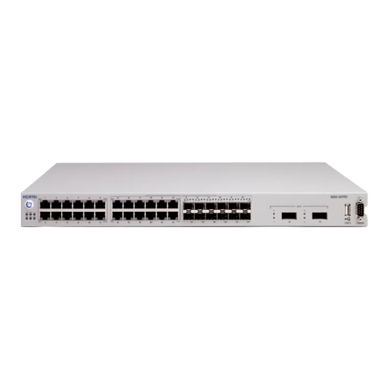
36 Installing the Nortel Ethernet Routing Switch Nortel Ethernet Routing Switch 5530-24TFD front panel User Interface Button 2. Switch LEDs 3. 10/100/1000 Mbps port LEDs 4. SFP Transceiver Port LEDs 5. Console Port 6. XFP Transceiver Port LEDs 7. USB Port Note: Copper ports 13 to 24 and the SFPs are shared ports on the Nortel Ethernet Routing Switch 5530-24TFD. - Page 37 Checking LEDs on the Nortel Ethernet Routing Switch 5500 Series 37 Label Color / Status Description Green / steady The switch is connected to AC power and is receiving power. Green / blinking Problem with primary Boot image. Booted from back up image. Configuration and agent code may be incorrect.
-
Page 38: Port Led State Indicators
This section outlines the state indicators provided by the port LED through color and fluctuation cues. Refer to the appropriate switch section for further information: • "Nortel Ethernet Routing Switch 5510-24T and 5510-48T" (page 39) • "Nortel Ethernet Routing Switch 5520-24T-PWR or 5520-48T-PWR" (page 39) - Page 39 Checking LEDs on the Nortel Ethernet Routing Switch 5500 Series 39 Nortel Ethernet Routing Switch 5510 and 5530 Port LED state indicators for 5510 and 5530 Switches Label Color / Status Description Speed Green / steady The port is set to operate at 1000 Mbps.
-
Page 40: Shared Sfp Transceiver Port Led State Indicators
"Related publications" (page 12)on page 16. XFP transceiver port LED indicators (5530-24TFD only) The Nortel Ethernet Routing Switch 5530-24TFD contains two XFP Transceiver Ports with two LEDs labeled Tx (Transmit) and Rx (Receive). "XFP transceiver port LED state indicators" (page 40) outlines the port states indicated by the color and fluctuation of the XFP Transceiver Port LEDs. -
Page 41: Setting Ip Parameters For The Nortel Ethernet Routing Switch 5500 Series
Setting IP parameters for the Nortel Ethernet Routing Switch 5500 Series 41 LED Color / Status Description Rx Amber / blinking XFP has been installed. No Signal Detected or XFP in Reset. Both Off No XFP installed. The Amber LEDs are usually only used during the boot process. Under normal operation, Green is the only color the XFP LED should emit. - Page 42 Connect to the switch using the terminal or terminal emulation application. After the Nortel banner is displayed, press CTRL + Y to display the main menu. The version of the main menu displayed is dependent on whether the switch is part of a standalone or stacked switch configuration.
-
Page 43: Installation
Setting IP parameters for the Nortel Ethernet Routing Switch 5500 Series 43 Reset to Default Settings... Shutdown Command... Command Line Interface... Logout... Use arrow keys to highlight option, press <Return> or <Enter> to select option. Stacked switch main menu IP Configuration/Setup... - Page 44 In the Default Gateway field, enter the appropriate default gateway in dotted-decimal notation. Note: If Nortel Ethernet Routing Switch 5500 Series switches are being stacked, ensure that one switch is set as the Base Unit. For more information on this topic, refer to system configuration guide noted in "Related publications"...
-
Page 45: Setting Ip Parameters Using The Console Port And Cli
Setting IP parameters for the Nortel Ethernet Routing Switch 5500 Series 45 Initial IP configuration is now complete. To continue with configuration operations, select the appropriate menu item. To disconnect from the switch select Logout from the main menu. —End—... - Page 46 46 Installing the Nortel Ethernet Routing Switch 46)"Stacked switch main menu" (page 46) illustrates the main menu for a stacked switch configuration. Standalone switch main menu IP Configuration/Setup... SNMP Configuration... System Characteristics... Switch Configuration... Console/Comm Port Configuration... Display Hardware Units...
- Page 47 Setting IP parameters for the Nortel Ethernet Routing Switch 5500 Series 47 Note: The default management VLAN in the Nortel Ethernet Routing Switch 5500 Series is VLAN 1. To manage the switch, ensure that the network management station is on the management VLAN or is connected to the management VLAN through routers.
-
Page 48: Setting Ip Parameters Using The Web-Based Management Interface
48 Installing the Nortel Ethernet Routing Switch Setting IP parameters using the Web-based Management Interface Note: IP parameters are changed during this procedure. Changes to IP parameters can result in the loss of web browser connectivity to the switch. To set IP parameters using the Web-based Management Interface, perform... -
Page 49: Setting Ip Parameters Using The Ui Button
Setting IP parameters for the Nortel Ethernet Routing Switch 5500 Series 49 assigned to the field by a BootP request. These fields are outlined the following table. IP Configuration fields Field Description In-Band Stack IP The IP address used by the switch when it is part Address of a stack. -
Page 50: Nortel Ethernet Routing Switch 5500 Series Stack Configuration
Nortel Ethernet Routing Switch 5500 Series Stack Configuration The Nortel Ethernet Routing Switch 5500 Series provides the capability for fail-safe stackability. Up to eight 5500 Series devices can be connected in a stack to provide uninterrupted connectivity for up to 384 ports. This stack is managed as a single unit. -
Page 51: Installation
Cascade Up connector completes the stack connection. Note: To create a stack connection, order the appropriate Nortel Ethernet Routing Switch 5500 Series cascade cables to ensure fail-safe stacking. These cables are not provided with the switch. For stacking three or more units (maximum 8 units per stack), order the 3 foot cascade max-return cable (order number AL2018009). -
Page 52: Stack Configuration
52 Installing the Nortel Ethernet Routing Switch Note: To create a stack connection, order the appropriate Nortel Ethernet Routing Switch 5500 Series cascade cables to ensure fail-safe stacking. These cables are not provided with the switch. The following illustration demonstrates the proper crossover connection configuration. - Page 53 Nortel Ethernet Routing Switch 5500 Series Stack Configuration 53 • "Abandoning a command" (page 54) Setting the Base Unit To set the stack base unit with the UI button, follow this procedure: Step Action Press and hold the UI button for three seconds.
- Page 54 54 Installing the Nortel Ethernet Routing Switch —End— Note: The switch does not become the non-base unit until the next time the switch is restarted. Resetting the stack To reset the stack using the UI button, follow this procedure: Step Action Press and hold the UI button for three seconds.
-
Page 55: Initial Installation
Nortel Ethernet Routing Switch 5500 Series Stack Configuration 55 Initial installation During the initial installation of the stack, the software automatically determines the physical order of all units in the stack according to the position of the base unit within the stack. Thereafter, the individual units maintain their original unit numbering, even if the position of one or more units in the stack is changed. -
Page 56: Replacing A Stack Unit
56 Installing the Nortel Ethernet Routing Switch • Console, Web, Telnet, and SNMP passwords • SNMP community strings Replacing a stack unit Note: Use only the console interface, command line interface, or Web-based management system to replace or insert units in the stack. -
Page 57: Stack Configurations
Nortel Ethernet Routing Switch 5500 Series Stack Configuration 57 Stack configurations Due to stack parameters being associated with the base unit, the physical stack order depends on the base unit position and whether the stack is configured cascade up (stack up) or cascade down (stack down). This designation depends on the stack cabling arrangement. -
Page 58: Installation
2. Last Unit 3. Cascade Cable 4. Cascade Cable Note: Since many network management software packages assume a cascade down (stack down) configuration, Nortel recommends the usage of this configuration. Nortel Ethernet Routing Switch 5500 Series Installation NN47200-300 2.00 Standard 5.0 7 July 2006... -
Page 59: Redundant Cascade Stacking
Redundant cascade stacking The Nortel Ethernet Routing Switch 5500 Series allows a stack of up to 8 units into a dual-path cascade stack. If any single unit fails or if a cable is accidently disconnected, other units in the stack remain operational without interruption. - Page 60 60 Installing the Nortel Ethernet Routing Switch Redundant cascade stacking 1. Base Unit 2. Last Unit 3. Cascade Cable 4. Cascade Cable Nortel Ethernet Routing Switch 5500 Series Installation NN47200-300 2.00 Standard 5.0 7 July 2006 Copyright © 2005 - 2006, Nortel Networks...
-
Page 61: Translations Of Safety Messages
Ogni unità deve essere fissata al rack con le staffe di montaggio appropriate. Le staffe di montaggio non sono state progettate per supportare più unità. Nortel Ethernet Routing Switch 5500 Series Installation NN47200-300 2.00 Standard 5.0 7 July 2006 Copyright ©... - Page 62 La rimozione della piastra impedisce la ventilazione e il corretto raffreddamento dell’unità. Nortel Ethernet Routing Switch 5500 Series Installation NN47200-300 2.00 Standard 5.0 7 July 2006...
- Page 63 En outre, vous devez dégager un espace minimal dans la zone de câblage pour pouvoir y accéder facilement en cas d’urgence. Nortel Ethernet Routing Switch 5500 Series Installation NN47200-300 2.00 Standard 5.0 7 July 2006...
-
Page 64: Installation
Senza un’adeguata messa a terra, chiunque tocchi lo switch corre il rischio di ricevere una scossa elettrica. L’assenza di un percorso per la messa a terra verso lo switch può comportare un eccesso di emissioni. Nortel Ethernet Routing Switch 5500 Series Installation NN47200-300 2.00 Standard 5.0 7 July 2006... - Page 65 La rimozione della piastra impedisce la ventilazione e il corretto raffreddamento dell’unità. Nortel Ethernet Routing Switch 5500 Series Installation NN47200-300 2.00 Standard 5.0 7 July 2006...
- Page 66 Collegare sempre il cavo di alimentazione ad una presa che sia facilmente e rapidamente accessibile in caso di emergenza. Nortel Ethernet Routing Switch 5500 Series Installation NN47200-300 2.00 Standard 5.0 7 July 2006...
- Page 67 Switch 15 Package contents 19 XFP installation 25 Phone dongle 15 XFP removal 26 Power specifications 30 Nortel Ethernet Routing Switch 5500 Series Installation NN47200-300 2.00 Standard 5.0 7 July 2006 Copyright © 2005 - 2006, Nortel Networks Nortel Networks Confidential...
- Page 68 68 Index Nortel Ethernet Routing Switch 5500 Series Installation NN47200-300 2.00 Standard 5.0 7 July 2006 Copyright © 2005 - 2006, Nortel Networks Nortel Networks Confidential...
-
Page 70: Installation
Sourced in Canada and the United States of America. The information in this document is subject to change without notice. Nortel Networks reserves the right to make changes in design or components as progress in engineering and manufacturing may warrant.
Need help?
Do you have a question about the 5500 series and is the answer not in the manual?
Questions and answers