Table of Contents
Advertisement
Quick Links
Advertisement
Table of Contents

Subscribe to Our Youtube Channel
Related Manuals for Elcometer 701


Summary of Contents for Elcometer 701
- Page 1 Elcometer 701 Live Cable Locator & Cable Avoidance Tool Operating Instructions...
- Page 2 (in a retrieval system or otherwise) or translated into any language, in any form or by any means (electronic, mechanical, magnetic, optical, manual or otherwise) without the prior written permission of Elcometer Limited. A copy of this Instruction Manual is available for download on our Website via www.elcometer. Doc.No. TMA-0429 Issue 03 Text with Cover No: 20528...
-
Page 3: Table Of Contents
About the Elcometer 701 ........ -
Page 4: About The Elcometer 701
Your Elcometer 701 Pipe and Cable Locator is a world beating product. With the purchase of this product you now have access to the worldwide service and support network of Elcometer. For more information visit our website at www.elcometer.com... -
Page 5: What The Box Contains
• Lines without a signal The Elcometer 701 Receiver can only locate lines which emit a signal; lines which do not emit a signal will not be located. If no lines have been found, it is important to always exercise extreme caution when digging. -
Page 6: Battery Care
ETTING STARTED To release the battery compartment cover, push the rubber button away from the instrument handle and then lift away the cover. The batteries are contained in an enclosure which must be removed from the instrument for access. Place the batteries in the enclosure ensuring correct polarity - refer to the diagrams on the enclosure. -
Page 7: The Receiver (Rx)
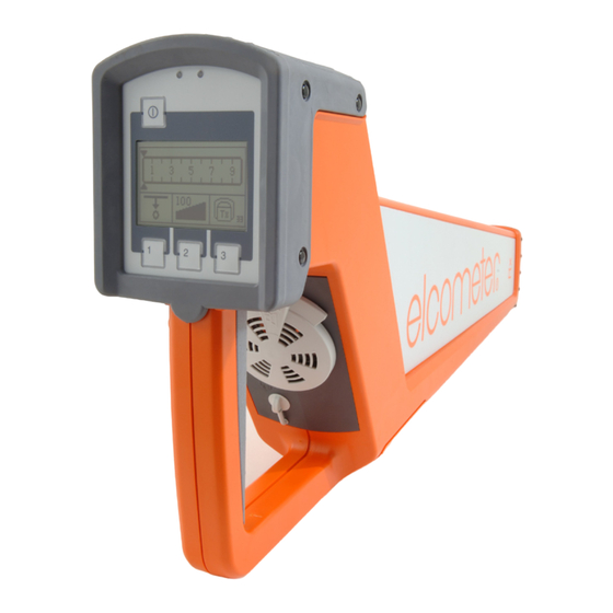
ETTING STARTED 3.3 The Receiver (Rx) 3.3.1 Parts of the instrument 1. Control panel with display 2. Speaker with volume control The speaker gives various acoustic signals (e.g. beeps with modulating pitch relative to the signal strength). Quieter Louder When the receiver is switched on, the volume is set at a standard level. -
Page 8: The Transmitter (Tx)
ETTING STARTED 3.4 The Transmitter (Tx) 1. Accessory connector sockets These sockets are used to create a direct galvanic connection to the target line or to create a connection using a special connection set (e.g. transmitter clamp or house connection set - see “Spare parts and optional accessories”... -
Page 9: When Do I Need To Use The Transmitter
ETTING STARTED 3.5 When do I need to use the transmitter? The receiver can be used with or without the transmitter. The table below illustrates the capabilities of the receiver when used with and without the transmitter. Transmitter (Tx) Receiver (Rx) Signal detection mode Locates Measures... -
Page 10: Transmitter - Use, Setup And Signal Coupling
RANSMITTER SETUP AND SIGNAL COUPLING 4 TRANSMITTER - USE, SETUP AND SIGNAL COUPLING 4.1 Using the transmitter Follow the steps listed below in order to prepare the transmitter to search for lines in conjunction with the receiver: Step Action Page Decide whether the transmitter signal is going to be coupled to the line by induction 10-15 or by direct connection. -
Page 11: Transmitter Setup Options
RANSMITTER SETUP AND SIGNAL COUPLING 4.2 Transmitter setup options 4.2.1 Signal characteristics The characteristics of the transmitter output signal can be configured by the user to meet the specific requirements of either the line to be located or the site to be surveyed: Symbol Description Notes... -
Page 12: Options For Direct And Inductive Signal Coupling
RANSMITTER SETUP AND SIGNAL COUPLING 4.3 Options for direct and inductive signal coupling There are four methods of coupling the signal from the transmitter to the line: • Direct coupling to cables and pipes (see below) • Coupling using special connection accessories (see page 13) •... - Page 13 RANSMITTER SETUP AND SIGNAL COUPLING • Single-wire lines or pipes (with or without insulation against earthing) The distance between the earth spike and the ends of the connected lines should be as great as possible. Note: It is possible that the return current will couple to adjacent lines, which could result in these lines also being detected.
- Page 14 RANSMITTER SETUP AND SIGNAL COUPLING • Metallic conduit (with or without insulation against earthing) The earth spike and the conduit should be spaced as far apart as possible. Under certain circumstances, optimum positioning of the earth spike may require several attempts. •...
- Page 15 TV connections and telephone jacks with the aid of a suitable adaptor cable. In doing so, it is not necessary to disconnect the lines. Elcometer offers a ready made house connection set for this type of coupling. • Coupling via transmitter clamp...
- Page 16 RANSMITTER SETUP AND SIGNAL COUPLING 4.3.3 Inductive signal coupling For lines which are not easily accessible, signal from transmitter has to be inductively coupled via the integrated antenna. This highly recommended unknown lines are to be located (e.g. at a construction site). To determine the orientation of a specific line, the transmitter has to be positioned directly above the line as...
- Page 17 RANSMITTER SETUP AND SIGNAL COUPLING 4.3.4 Signal coupling in non-metallic pipes (The Probe described in this section is an optional accessory - see “Spare parts and optional accessories” on page 28). With the aid of the Probe, the signal from the transmitter signal can be transmitted through non-metallic...
-
Page 18: Receiver - Use, Adjusting Sensitivity And Setup
ECEIVER ADJUSTING SENSITIVITY AND SETUP 5 RECEIVER - USE, ADJUSTING SENSITIVITY AND SETUP 5.1 Using the receiver Step Action If the site is to be searched with the aid of the transmitter, the transmitter must be switched on and set up before proceeding. Switch on the receiver. -
Page 19: Adjusting The Sensitivity Level To Match The Received Signal Strength
ECEIVER ADJUSTING SENSITIVITY AND SETUP 5.2 Adjusting the sensitivity level to match the received signal strength The strength of the received signal and the sensitivity of the receiver are shown in the following segments of the display: 1. Received signal strength meter The strength of the received signal is represented by this bargraph scale. -
Page 20: Receiver Setup Options
Power Grid For locating mains power supply cables, through which current with a grid frequency (50 Hz/60 Hz) is flowing. Transmitter For locating cables or pipes, which are carrying a signal coupled from the Elcometer 701 transmitter... - Page 21 ECEIVER ADJUSTING SENSITIVITY AND SETUP 5.3.2 To select depth measurement type and units: Step Action Switch off the receiver. Press and hold button # 1. While continuing to hold button # 1, press and release the power on/off button. The instrument will switch on and then beep. Release button # 1.
-
Page 22: Surveying A Site
URVEYING A SITE 6 SURVEYING A SITE Your Elcometer 701 Pipe and Cable Locator is the ideal instrument to use if a site needs to be searched for cables and pipes. Typically there may be inaccurate or no information available as to the location and orientation of cables and pipes on a site planned for construction (e.g. -
Page 23: Determining The Direction Of A Line
ETERMINING THE DIRECTION OF A LINE 7 DETERMINING THE DIRECTION OF A LINE Follow the steps below to determine the orientation of a metallic conductor: Step Action If the direction of the conductor is to be determined with the aid of the transmitter, couple the transmitter's signal to the metallic conductor in such a way that there is as little signal loss as possible and switch on the transmitter. -
Page 24: Determining The Depth Of A Line
This is particularly important if depth is measured using the manual method. 8.1 Depth measurement - automatic The Elcometer 701 receiver has an automatic depth measurement feature. This feature will only operate if the following conditions are met: •... - Page 25 ETERMINING THE DEPTH OF A LINE Step Action Rotate the receiver (through its own axis) over this location until the maximum signal strength is indicated. Result: The receiver is in line with the conductor when it is positioned where the signal is strongest, which is prerequisite for determining the depth of the line.
- Page 26 ETERMINING THE DEPTH OF A LINE 8.5 Indications and error messages During the depth measuring process, the following symbols are used to notify the user about certain characteristics and errors: For one of the following reasons, the depth could not be measured: •...
-
Page 27: Masking-Out Lines
ASKING OUT LINES 9 MASKING-OUT LINES Under certain circumstances lines at lower depths can 'hide' deeper, adjacent lines, thus making it more difficult to locate them. In such cases, the transmission characteristics of the transmitter can be fully utilised and the lines which have already been located can be masked out. -
Page 28: Technical Specification
ECHNICAL SPECIFICATION 10 TECHNICAL SPECIFICATION 10.1 Elcometer 701 Receiver (Rx) Frequency range Range 1: radio 15 kHz to 23 kHz Range 2: power grid 50 Hz / 60 Hz (switchable) (optionally 100 Hz - contact Elcometer) Range 3: transmitter 32.768 kHz... - Page 29 Type of protection (in accordance with EN 60529) Dust and water protected IP 56 10.3 Limit values and standards The following limit values and standards are applicable for the Elcometer 701 RxTx location system: Sinusoidal vibrations (in accordance with EN 60068-2-6) Peak acceleration...
-
Page 30: Maintenance
AINTENANCE 11 MAINTENANCE The Elcometer 701 Pipe and Cable Locator is designed to give many years reliable service under normal operating and storage conditions. The Elcometer 701 Pipe and Cable Locator does not contain any other user-serviceable components. In the unlikely event of a fault, the instrument should be returned to your local Elcometer supplier or directly to Elcometer.
Need help?
Do you have a question about the 701 and is the answer not in the manual?
Questions and answers