Advertisement
Advertisement
Table of Contents

Related Manuals for Victor 6056B


Summary of Contents for Victor 6056B
- Page 1 User’s Manual of Digital Clamp Multimeter...
-
Page 2: Table Of Contents
Table of Contents 1. General……………………………………….1 2. Unpacking Check…………………………….2 3. Safety Notices…………………. …………….2 4. Common Electric Symbols…………….…….5 5. External Structure…………………………….6 6. Symbols Displayed…………………………….7 7. Functions of Key and Automatic Power-off….8 8. Effectiveness of Keys………………………….9 9. Characteristics…………………………………10 10. Maintenance and Care……………………….26... -
Page 3: General
I. General It is a 3 3/4-bit digital clamp meter of automatic range conversion and a high-reliability digital clamp multimeter with stable performance and driven by battery. It adopts 16mm font height LCD display of clear readings. With the functions of data holding and automatic power-off, it is more convenient to use. -
Page 4: Unpacking Check
II. Unpacking Check After unpacking, please carefully check if the following items are missing or damaged. If yes, please contact the distributor immediately. ■ Digital clamp multimeter 1 set ■ User’s manual 1 piece ■ Test leads 1 set ■ 9V battery 1 piece III. - Page 5 CAT III 600V and Grade II pollution. Before use, please read this manual carefully. 1. When measuring the voltage above 30V, the AC electric line with inductive loads and the AC electric line during electric fluctuation, be cautious against electric shock. 2.
- Page 6 measured point and make sure there are no signals on the input end. 5. During the electric measurement, never directly touch the ground or touch naked metal terminals, output ports, lead clamps, etc that may have ground potential. 6. Do not store and use the meter in the environment of high temperature, high humidity, high flammability, high explosion potential and strong magnetic field.
-
Page 7: Common Electric Symbols
be sure to disconnect the test probe cable from the tested item and make sure there are no signals input into the input end. Never convert the function/range selection switch during measurement. 10. When the LCD display shows “ ”, please replace the battery in time to ensure the measurement accuracy. -
Page 8: External Structure
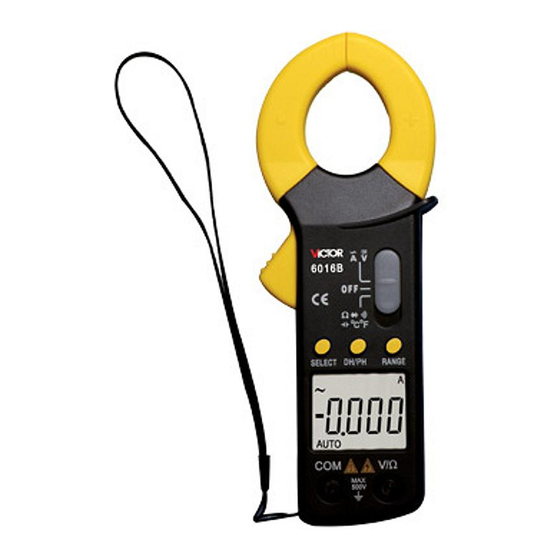
V. External Structure 1. Clamp head; 2. Clamp head trigger; 3. Function selection (SELECT) key; 4. Reset (REL) key; 5. LCD display; 6. COM input port: Negative input terminal with black test probe inserted; 7. VΩ input port: Positive input terminal for measuring voltage, resistance, capacity, frequency, diode and continuity with red test probe inserted here;... -
Page 9: Symbols Displayed
VI. Symbols Displayed 1. Negative sign; 2. AC signal measurement sign; 3. DC signal measurement sign; 4. Automatic range sign; 5. Diode measurement sign; 6. Buzzer symbol; 7. Relative value measurement sign; 8. Data hold sign; 9. Low battery sign; 10. -
Page 10: Functions Of Key And Automatic Power-Off
VII. Functions of Keys and Automatic Power-off (1) SELECT: Selects functions in the trigger mode. When two or above measurement functions combine at the same gear, press this key to convert measurement functions. (2) HOLD: Holds readings in the trigger mode. Press this key to lock the displayed value and press it again to relieve the locking state and then enter the normal measurement state. -
Page 11: Effectiveness Of Keys
5μA) will be consumed. If the meter is not used for long, be sure to shut off its power. (5) Buzzer: Press any function key at any gear; if such key is valid, the buzzer will buzz; if invalid, the buzzer will not buzz;... -
Page 12: Characteristics
IX. Features 1. General Features 1-1. Display mode: LCD display; 1-2. Max. display: 3999(3 3/4)bit auto polar display or unit display; 1-3. Measurement mode: Dual slope A/D conversion; 1-4. Conversion rate: 3 times/s; 1-5. Over-range display: “OL” displayed in the highest 1-6. - Page 13 1-14. Power supply: 9V battery; 1-15. Volume (dimensions): 225mm×76mm×32mm (L×W×H) ; 1-16. Approx. 270g (battery included). 2. Technical Accuracy: ± (a% of reading + word count) with accuracy ensured. Ambient temperature: (23±5)℃, RH<75%; calibration warranty period as one year from ex-works date. 2-1.
- Page 14 B) Respectively insert the red test probe and black test probe into the VΩ and COM ends. C) Parellelly connect the test probe cable onto the tested circuit or the power supply, then the polarity of the red test probe cable and the tested voltage value will be shown on the screen.
- Page 15 2-2 . ACV Measurement A) Turn the function/range SELECT switch gear.. B) Respectively insert the red test probe and black test probe into the VΩ and COM ends. C) Parellelly connect the test probe cable onto the tested circuit or the power supply. D) Read the currently measured result from the display.
- Page 16 ACV Technical Indicators (True RMS) Range Accuracy Resolution ±(0.8%+10d) 10mV 400V 100mV 750V ±(1.0%+10d) Input resistance: 10MΩ. Frequency response: sine wave and triangle wave :(40~1000)Hz ,other wave form :(40~200)Hz; Display: True RMS Overload protection: 1000V DC or AC peak. Note: •...
- Page 17 C) Parellelly connect the test probe cable onto the tested resistor, then the tested resistance value will be shown on the screen. D) Read the currently measured result from the display. Note: • When the online resistor is measured, be sure to shut off the line power supply and discharge all capacitors completely.
- Page 18 • When the resistance above 1MΩ is measured, the reading on the meter will not be stable until several seconds have passed. This is normal for high-resistance measurement. • When the resistor is measured, do not input voltage value. Never input the voltage above the overload protection, otherwise, the meter may be damaged and the operator may be hurt.
- Page 19 Note: When 400Ω is used, it is necessary to short circuit the test probe to test the resistance of the lead, which will be deducted from the actual test. 2-4. Diode Measurement and Continuity Test 2-4-1. Diode Measurement A) Turn the function/range SELECT switch gear.
- Page 20 Note: • In case of open diode or reverse polarity, the display will show “OL”. • When the online diode is measured, be sure to shut off the line power supply and discharge all capacitors completely. • After the measurement is over, immediately disconnect the test probe and the tested circuit.
- Page 21 continuity measurement function. C) Respectively insert the red test probe and black test probe into the VΩ and COM ends. D) Parallelly connect the test probes onto the both ends of the tested circuit. E) If the resistance between both ends of the circuit is less than about 50Ω, the built-in buzzer will sound.
- Page 22 Note: • If the tested circuit is open, the display will show “OL”. • In case of line continuity test, be sure to shut off the line power supply and discharge all capacitors. • After the measurement is over, immediately disconnect the test probe and the tested circuit.
- Page 23 C) Press the REL key to clear. D) Respectively insert the red test probe and black test probe into the VΩHz and COM ends. E) Parellelly connect the testing end of the test probe cable onto the tested capacitor and then the tested capacitance value will be shown on the display.
- Page 24 Note: • The measurement of capacitance below 4nF is for reference only. • When the online capacitor is measured, be sure to shut off the line power supply and discharge the capacitor completely. • It will take long time to measure large capacitance. •...
- Page 25 shown in the right figure. B) Respectively insert the red test probe and black test probe into the VΩ and COM ends. C) Parellely connect testing end of the test probe onto the signal source to be tested. D) Read the measured result from the display. Frequency Indicator: Range Accuracy...
- Page 26 Note: • Do not input the signal above 250V, otherwise, the meter may be damaged and the user may be hurt. • After the measurement is over, immediately disconnect the test probe and the tested circuit. • The signal measurement value above 1000 kHz is for reference only.
- Page 27 head to clamp the conductor to be tested and then release the trigger slowly until the head is closed completely. Please confirm if such conductor is clamped in the center of the head because such conductor not placed in the center will cause additional error.
-
Page 28: Maintenance And Care
Note: 1. AC frequency response: 50~60Hz; 2. If this meter is near to any place with strong magnetic field, it will display unstable or incorrect induction reading that does not affect the measurement result. X. Maintenance and Care Warning: In order to prevent electric shock, before opening the bottom cover, take the test bar away. - Page 29 cloth and mild detergent rather than strong solvents as abrasive, alcohol, etc; 1-5. If the battery is not used for long, please take it out in order to prevent the leakage from corroding this meter; 1-6. Do not use DC or AC peak voltage more than 1000V;...
- Page 30 2.3. Take out the old battery and install new battery according to the polar indication. 2-4. Please use the battery with the same model rather than improper battery. 2-5. After installing new battery, insert the lid and tighten the screws.
- Page 31 This user’s manual is subject to any change without further notice. The content in this user’s manual is deemed correct; if you find any mistake, omission, etc, please contact the manufacturer. We will not be held liable for any accidents or harms caused due to your wrong operations.
Need help?
Do you have a question about the 6056B and is the answer not in the manual?
Questions and answers