Table of Contents
Advertisement
Quick Links
A product of:
OPERATOR'S MANUAL
ALL
VERSIONS
OGI# 460346 SOLAR POWER
OGI# 460347 100-240 VAC
OGI# 460348 12-24 VDC
When you purchase a TotalArc BMS you purchase a product of "Quality, integrity, and innovation from concept to
commissioning." That promise, along with proper maintenance, will ensure that your TotalArc BMS gives you years of
rugged, trouble-free performance. Thank you for your purchase.
To reduce the risk of injury, the user must read and understand the operator's manual before using
WARNING:
this product.
SAVE THIS MANUAL FOR FUTURE REFERENCE
Advertisement
Table of Contents

Related Manuals for OGI TotalArc BMS 460346 SOLAR POWER

Summary of Contents for OGI TotalArc BMS 460346 SOLAR POWER
- Page 1 A product of: OPERATOR’S MANUAL VERSIONS OGI# 460346 SOLAR POWER OGI# 460347 100-240 VAC OGI# 460348 12-24 VDC When you purchase a TotalArc BMS you purchase a product of “Quality, integrity, and innovation from concept to commissioning.” That promise, along with proper maintenance, will ensure that your TotalArc BMS gives you years of rugged, trouble-free performance.
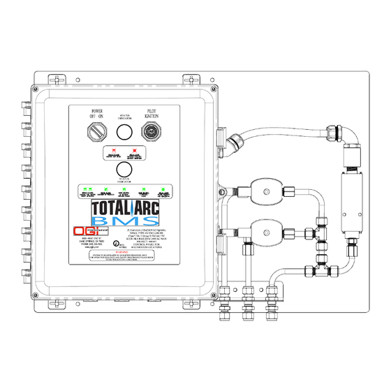
- Page 2 See this section for all the figures referenced in the operator’s manual. Figure 1: ON/OFF POWER SWITCH RED STATUS INDICATOR LIGHT IGNITION PUSH BUTTON GREEN STATUS INDICATOR LIGHT TOTALARC ENCLOSURE TOTALARC MAIN GAS VALVE TOTALARC PILOT GAS VALVE TEMPERATURE CONTROL PRESSURE SWITCH CUSTOMER POWER ENTRY 10.
- Page 3 FIGURE 2: IGNITION MODULE Installation in Flame Arrestor For details see Installation instructions on page 7...
- Page 4 FIGURE 3A: INSTALLATION TotalArc kit includes mounting feet for easy installation For details see Installation instructions on page 6 FIGURE 3B: MOUNTING HOLE DIMENSIONS MOUNTING PATTERN FOR TOTALARC BMS SYSTEM BACKPLATE...
- Page 5 FIGURE 4: Clamshell Installation FIGURE 5: Battery Connection Detail SOLAR OPTION ONLY...
- Page 6 FIGURE 6: Ignition Rod Installation...
- Page 7 FIGURE 7: ASCO Flow Diagrams FIGURE 6: Ignition Rod Installation...
- Page 8 Figure 8: Solar Panel Assembly...
- Page 9 Figure 9: Solar Panel Assembly VIII...
- Page 10 Figure 10: Tubing Diagram For more details see P&ID in Operations Section VIIII...
-
Page 11: Table Of Contents
TABLE OF CONTENTS Introduction ..................................1 Important Safety Instructions ............................2 Symbols ..................................3-4 Electrical ..................................4 Features ..................................5 Assembly ..................................5-7 Operation ..................................8-9 Maintenance.................................. 10 Trouble Shooting ..............................11-12 Wiring Diagrams ..............................13-14 Warranty ..................................15 Parts Ordering and Service .......................... Back Page... -
Page 12: Introduction
RTU power source that will typically have a built-in power back up. **The TotalArc BMS is a fully customizable productline – other options are available upon request. Please speak to an OGI Sales Representative to discuss options to fit your needs** * * *... -
Page 13: Important Safety Instructions
General location. ◼ If BMS is not working as it should, call OGI service ◼ To reduce the risk of electric shock, this control system has department, available 24/7 to assist you with polarized connection points. -
Page 14: Symbols
SYMBOLS The following signal words and meanings are intended to explain the levels of risk associated with this product. SYMBOL SIGNAL MEANING Indicates a hazardous situation, which, if not avoided, will result in death or DANGER: serious injury. (Without Safety Alert Symbol) Indicates information considered important, but NOTICE: not related to a potential injury (e.g. -
Page 15: Electrical
Watt Power Time Minutes ELECTRICAL ◼ OGI PART# 460346 Solar Powered Control Panel Nominal System Voltage: 12 VDC Rated Solar Input: 6A Max. Solar Voltage: 30 VDC Regulation Voltage: 14.1 VDC at 25°C ◼ OGI PART# 460347 VAC Powered Control Panel Nominal System Voltage: 85 - 264 VAC Rated Current Input: 1.35A at 120 VAC/0.65A at 230 VAC... -
Page 16: Features
PACKING LIST OGI# 460346 – TotalArc BMS Solar: SHIP LOOSE ITEMS ▪ TotalArc BMS System If the TotalArc system is shipped with an OGI Heater the ▪ Solar Panel w/ attached cable following components will be shipped separately as loose ▪... - Page 17 ASSEMBLY POWER CONNECTIONS IGNITION MODULE INSTALLATION This product requires assembly. The TotalArc system is shipped full factory wired except for the power system. See wiring instructions ◼ Ignition module must be installed inside the for all power options: flame arrestor via two 1 ¼” diameter hole in the flame arrestor wall.
- Page 18 ASSEMBLY ◼ The ignition rod’s position can be adjusted by Battery Connection: using a 7/64” allen wrench and loosening a set screw on the rod’s clamp. Once the position is 1. The 120VAC TotalArc model has a din rail set, tighten the set screw. mounted battery pack that is pre-wired at ◼...
-
Page 19: Operation
OPERATION The TotalArc BMS is a flame controlling system that monitors a call for heat from pneumatic controllers upstream of the device. When the system receives a call for heat it will attempt to light the pilot, prove the pilot for ten seconds, then ignite the main burner. - Page 20 OPERATION TOTALARC BMS LIGHT CODES SYMBOL DESCRIPTION MEANING POSSIBLE CAUSES INITIAL POWER ON; AFTER RED LIGHT: SINGLE FLASH WAITING FOR RESET CORRECTED SAFETY FAULT FAILURE TO LIGHT PILOT; FAILURE TO LOCKOUT RED LIGHT: SOLID LIGHT MAIN GAS; SAFETY FAILURE CONDITION EVENT OCCURS WHEN UNIT IS WAITING FOR GREEN LIGHT: DOUBLE...
- Page 21 OPERATION...
-
Page 22: Maintenance
Check Battery Voltage. REPAIRS ALL REPAIRS MUST BE MADE BY A QUALIFED TECHNICIAN. OGI ACCEPTS NO RESPONSIBILITY FOR REPAIRS MADE BY NON-FACTORY AUTHORIZED PERSONNEL. NATURAL GAS IS A DANGEROUS SUBSTANCE - APPROPRIATE PRECAUTIONS MUST BE TAKEN TO AVOID ACCIDENTS. -
Page 23: Troubleshooting
TROUBLESHOOTING ISSUE SIGNAL MEANING REACTION POTENTIAL CAUSES • Improper positioning of Pilot Does Not SOLID RED LOCKOUT System shuts down ignitor/flame rod to Pilot Head Light LIGHT CONDITION and waits for Operator (See figure 6 Page IV) reset • Poor ground between Relighter Ignition Module (in flame arrestor) and Pilot Head Low Battery Voltage (11.50 Volt... - Page 24 TotalArc enclosure terminal blocks and from the solar converter SK-6 to the panel terminal blocks. o If there are no areas of concern, please contact OGI Service Department for further trouble shooting. VAC System ❑...
- Page 25 SCHEMATICS SOLAR POWER TOTALARC (P/N 460346) TSI = TERMINAL STRIP LOCATED IN BATTERY ENCLOSURE TS2 = TERMINAL STRIP LOCATED IN BMS ENCLOSURE *NOTE: Only Solar Systems have a FU2 due to remote battery enclosure 120VAC POWER TOTALARC (P/N 460347) 12-24VDC POWER TOTALARC (P/N 460348)
- Page 26 SCHEMATICS Enclosure Connections for all systems:...
- Page 27 SCHEMATICS Enclosure Connections for all systems (CONT.):...
-
Page 28: Warranty
WARRANTY OGI Process Equipment, Inc. Warranty and Performance Guarantee Statement: corresponding credit from Seller guarantees the goods it manufactures, component manufacturer. This as stated herein, to be free from defective warranty is provided to the original materials and workmanship for a period of Purchaser and is not transferable.
Need help?
Do you have a question about the TotalArc BMS 460346 SOLAR POWER and is the answer not in the manual?
Questions and answers