Table of Contents
Advertisement
Quick Links
Instructions – Parts List
Parts
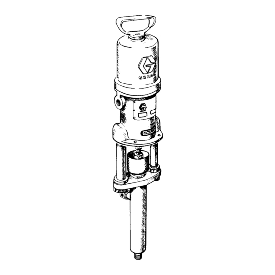
STAINLESS STEEL
30:1 Ratio President Pump
3600 psi (25.2 MPa, 252 bar) Maximum Working Pressure
Model 206897, Series F
Read warnings and instructions.
GRACO INC. P.O. BOX 1441 MINNEAPOLIS, MN 55440-1441
Copyright 1997, Graco Inc. is registered to I.S. EN ISO 9001
306769 Rev.G
Advertisement
Table of Contents

Related Manuals for Graco 206897


Summary of Contents for Graco 206897
- Page 1 30:1 Ratio President Pump 306769 Rev.G 3600 psi (25.2 MPa, 252 bar) Maximum Working Pressure Model 206897, Series F Read warnings and instructions. GRACO INC. P.O. BOX 1441 MINNEAPOLIS, MN 55440-1441 Copyright 1997, Graco Inc. is registered to I.S. EN ISO 9001...
- Page 2 INSTRUCTIONS D Read all instruction manuals, tags, and labels before operating the equipment. D Use the equipment only for its intended purpose. If you are not sure, contact your Graco distribu- tor. D Do not alter or modify this equipment.
-
Page 3: Toxic Fluid Hazard
WARNING WARNING INJECTION HAZARD Spray from the gun, leaks, or ruptured components can inject fluid into your body and cause extremely serious injury, including the need for amputation. Fluid splashed into the eyes or onto the skin can also cause serious injury. D Fluid injected into the skin might look like just a cut, but it is a serious injury. -
Page 4: Fire And Explosion Hazard
WARNING WARNING FIRE AND EXPLOSION HAZARD Improper grounding, poor ventilation, open flames, or sparks can cause a hazardous condition and result in a fire or explosion and serious injury. D Ground the equipment and the object being sprayed. Refer to Grounding on page 5. D If there is any static sparking or you feel an electric shock while using this equipment, stop spraying immediately. -
Page 5: Installation
Installation D Air and fluid hoses: Use only electrically conductive NOTE: Reference numbers and letters in parentheses refer to callouts in the figures and parts drawing. hoses with 500 ft (150 m) maximum combined hose length to ensure grounding continuity. Mount the pump to suit the type of installation planned. - Page 6 For assistance in designing a system to Install the air line accessories in the approximate order suit your needs, contact your Graco representative. shown in the Typical Installation. Install the bleed-type master air valve (A) within easy reach of WARNING the pump.
-
Page 7: Operation
Operation Pressure Relief Procedure 4. Unlock the gun/valve trigger safety. 5. Hold a metal part of the gun/valve firmly to a WARNING grounded metal waste container and trigger to relieve the fluid pressure. PRESSURIZED EQUIPMENT HAZARD The system pressure must be manually 6. - Page 8 Always stop the pump at the bottom of its stroke to prevent fluid from drying on the rod and damaging the Fill the packing nut/wet-cup 1/2 full with Graco Throat throat packings. Seal Liquid or a compatible solvent. Keep the cup filled...
-
Page 9: Troubleshooting
Troubleshooting NOTE: Check all possible problems and solutions WARNING before disassembling the pump. To reduce the risk of serious injury whenever you NOTE: Before servicing this equipment, always make are instructed to relieve pressure, always follow the sure to relieve the pressure. Pressure Relief Procedure on page 7. - Page 10 D For best results, always replace the glands when If you must remove the sleeve, and it does not replacing the packings. come out easily, contact your Graco representative. Install the new sleeve with the D Use a compatible solvent to clean parts. Inspect for tapered end down.
- Page 11 Service Reassembly (See Figs. 2, 3, and 4) 10. Apply low air pressure (about 40 psi (280 kPa, 2.8 bar) to the motor. Adjust the locknut on the small 1. Lubricate all parts. mounting tube (3) until the pump is running smoothly.
- Page 12 Parts 1/4 npt The dimension from the bottom backup washer (110 to the top of the retainer (113) must be 1.02 in (25.9 mm). Place the required quantity (0–3) of shims (129) between the gland (111) and washer (110) to maintain this dimension.
- Page 13 Parts Model 206897 Ref. No. 1 30:1 President Pump, Series F Displacement Pump Includes items 1–11 Includes items 101–121 Ref. Ref. Part No. Description Qty. Part No. Description Qty. 206184 DISPLACEMENT PUMP 101* 100063 PIN, cotter; 1/16” dia.; 1” lg...
-
Page 14: Technical Data
Technical Data Category Data Maximum working pressure 3600 psi (25.2 MPa, 252 bar) Fluid pressure ratio 30:1 Air pressure operating range 40–120 psi (280–480 kPa, 2.8–8.4 bar) Delivery 1 gpm (4 lpm) Maximum recommended pump speed 60 cycles per minute Cycles per gallon (liter) 62 (16) Air motor effective diameter... - Page 15 Dimensions Mounting Hole Layout 16–3/8” 7–1/4” (414.7 mm) (184.2 mm) DIA. 3/8 npt IN 35” 5–3/8”” (889 mm) (135.3 mm) 161322 GASKET (not supplied) 2–3/4”” THREE 11/32” (8.7 mm) (69.9 mm) DIA. HOLES ON 18–5/8”” 6–3/8” (160.7 mm) (474 mm) BOLT CIRCLE 1/4 npt 12–7/8””...
-
Page 16: Graco Standard Warranty
Graco distributor to the original purchaser for use. With the exception of any special, extended, or limited warranty published by Graco, Graco will, for a period of twelve months from the date of sale, repair or replace any part of the equipment determined by Graco to be defective.
Need help?
Do you have a question about the 206897 and is the answer not in the manual?
Questions and answers