Graco Reactor E-20 Series Operation Manual
Electric, heated, plural component proportioner
Hide thumbs
Also See for Reactor E-20 Series:
- Manual (76 pages) ,
- Electrical diagrams (12 pages) ,
- Repair parts (72 pages)
Table of Contents
Advertisement
Quick Links
Operation
Electric, Heated, Plural Component Proportioner
For spraying polyurethane foam and polyurea coatings. For professional use only.
Not approved for use in explosive atmospheres or hazardous (classified) locations.
Important Safety Instructions
Read all warnings and instructions in this
manual before using the equipment.
Save these instructions.
See page 4 for model information, including maximum
working pressure and approvals.
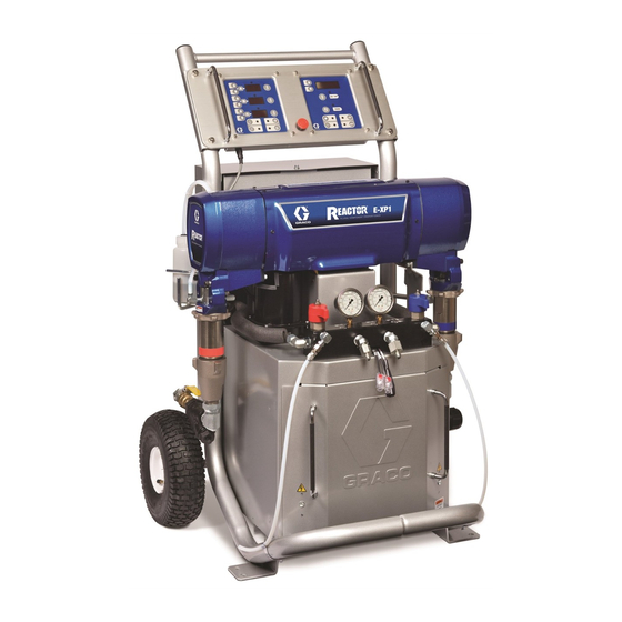
Model E-XP1 Shown
312065V
EN
Advertisement
Table of Contents

Subscribe to Our Youtube Channel
Related Manuals for Graco Reactor E-20 Series


Summary of Contents for Graco Reactor E-20 Series
- Page 1 Operation 312065V Electric, Heated, Plural Component Proportioner For spraying polyurethane foam and polyurea coatings. For professional use only. Not approved for use in explosive atmospheres or hazardous (classified) locations. Important Safety Instructions Model E-XP1 Shown Read all warnings and instructions in this manual before using the equipment.
-
Page 2: Table Of Contents
Graco Standard Warranty ....42 Graco Information ......42... -
Page 3: Systems
Systems Systems Maximum Fluid Heated Hose Working Proportioner Part Chamber 10 ft (3 m) Pressure (see page 4) 50 ft (15 m) Model Part (Qty 1) (Qty 1) psi (MPa, bar) ® AP9024 2500 (17.2, 172) 259024 246679 246055 246100 AR2020 Fusion AP9025... -
Page 4: Models
Models Models E-20 SERIES Max Flow Approximate Primary Maximum Fluid Part, Full Load Nominal Voltage System Rate Output per Heater Working Pressure Series Peak Amps* Range (phase) Watts† lb/min Cycle (A+B) Watts psi (MPa, bar) (kg/min) gal. (liter) 259025, G 200-240 V (1) 10,200 6,000... -
Page 5: Supplied Manuals
The following manuals are for accessories used with the Proportioner. Refer to these manuals for detailed Reactor. equipment information. Manual in Description English Manuals are also available at www.graco.com. Reactor Data Reporting Kit, Manual in 309867 Description Instruction-Parts Manual English... -
Page 6: Warnings
Warnings Warnings The following warnings are for the setup, use, grounding, maintenance, and repair of this equipment. The exclamation point symbol alerts you to a general warning and the hazard symbol refers to procedure-specific risk. Refer back to these warnings. Additional, product-specific warnings may be found throughout the body of this manual where applicable. - Page 7 Warnings WARNING SKIN INJECTION HAZARD High-pressure fluid from dispensing device, hose leaks, or ruptured components will pierce skin. This may look like just a cut, but it is a serious injury that can result in amputation. Get immediate surgical treatment. •...
- Page 8 Warnings WARNING THERMAL EXPANSION HAZARD Fluids subjected to heat in confined spaces, including hoses, can create a rapid rise in pressure due to the thermal expansion. Over-pressurization can result in equipment rupture and serious injury. • Open a valve to relieve the fluid expansion during heating. •...
- Page 9 Warnings WARNING MOVING PARTS HAZARD Moving parts can pinch, cut or amputate fingers and other body parts. • Keep clear of moving parts. • Do not operate equipment with protective guards or covers removed. • Equipment can start without warning. Before checking, moving, or servicing equipment, follow the Pressure Relief Procedure and disconnect all power sources.
-
Page 10: Important Isocyanate (Iso) Information
Important Isocyanate (ISO) Information Important Isocyanate (ISO) Information Isocyanates (ISO) are catalysts used in two component materials. Isocyanate Conditions Spraying or dispensing fluids that contain isocyanates creates potentially harmful mists, vapors, and atomized particulates. • Read and understand the fluid manufacturer’s warnings and Safety Data Sheets (SDSs) to know specific hazards and precautions related to isocyanates. -
Page 11: Material Self-Ignition
Important Isocyanate (ISO) Information Material Self-Ignition NOTE: The amount of film formation and rate of crystallization varies depending on the blend of ISO, the humidity, and the temperature. Foam Resins with 245 fa Some materials may become self-igniting if applied Blowing Agents too thick. -
Page 12: Typical Installation, With Circulation
Typical Installation, with circulation Typical Installation, with circulation TI10976a * Shown exposed for clarity. Wrap with tape during operation, . 1: Typical Installation, with circulation Reactor Proportioner Feed Pump Air Supply Lines Heated Hose Fluid Supply Lines Fluid Temperature Sensor (FTS) Feed Pumps Heated Whip Hose Agitator... -
Page 13: Typical Installation, Without Circulation
Typical Installation, without circulation Typical Installation, without circulation TI10975a * Shown exposed for clarity. Wrap with tape during operation, . 2: Typical Installation, without circulation Reactor Proportioner Waste Containers Heated Hose Fluid Supply Lines Fluid Temperature Sensor (FTS) Feed Pumps Heated Whip Hose Agitator Fusion Spray Gun... -
Page 14: Component Identification
Component Identification Component Identification TI9880a TI7823a . 3: Component Identification (Model EXP-1 Shown) BA Component A Pressure Relief Outlet DG Drive Gear Housing BB Component B Pressure Relief Outlet EC Electrical Cord Strain Relief FA Component A Fluid Manifold Inlet (behind manifold block) EM Electric Motor FB Component B Fluid Manifold Inlet FH Fluid Heaters (behind shroud) -
Page 15: Temperature Controls And Indicators
Temperature Controls and Indicators Temperature Controls and Indicators NOTICE To prevent damage to the softkey buttons, do not press the buttons with sharp objects such as pens, plastic cards, or fingernails. Heater Power Indicators Heater Displays Zone A Arrow Keys Heater A On/Off Key Zone B Arrow Keys Heater B On/Off Key... -
Page 16: Actual Temperature Key/Led
Temperature Controls and Indicators Actual Temperature Key/LED Temperature Displays Show actual temperature or target temperature of Press to display actual temperature. heater zones, depending on selected mode. Defaults to actual at startup. Range is 32-190°F (0-88°C) for A and B, 32-180°F (0-82°C) for hose. Press and hold to display electrical current. -
Page 17: Motor Controls And Indicators
Motor Controls and Indicators Motor Controls and Indicators NOTICE To prevent damage to the softkey buttons, do not press the buttons with sharp objects such as pens, plastic cards, or fingernails. Pressure/Cycle Display Arrow Keys Motor ON/OFF Key ON / OFF PARK Key PARK Pressure Key... -
Page 18: Pressure Arrow Keys
Spray Adjustments Spray Adjustments Pressure Arrow Keys Flow rate, atomization, and amount of overspray are Press to adjust fluid pressure when affected by four variables. motor is ON. Setpoint displays for 10 sec. • Fluid pressure setting. Too little pressure results in an uneven pattern, coarse droplet size, low flow, When motor is OFF, pressing will enter jog... -
Page 19: Setup
Setup Setup General equipment guidelines NOTICE Proper system setup, start up, and shutdown • Determine the correct size generator. Using the procedures are critical to electrical equipment correct size generator and proper air compressor reliability. The following procedures ensure steady will enable the proportioner to run at a nearly voltage. -
Page 20: Grounding
Setup Grounding Electrical requirements Installing this equipment requires access to parts • Reactor: is grounded through power cord. See which may cause electric shock or other serious injury Connect electrical cord, page 21. if work is not performed properly. Have a qualified electrician connect power and ground, see Connect •... -
Page 21: Connect Electrical Cord
Setup Connect electrical cord Connect feed pumps 1. Install feed pumps (K) in component A and B supply drums. See F . 1 and F . 2, pages 12 and 13. 2. Seal component A drum and use desiccant dryer NOTE: Power cord is not supplied. -
Page 22: Install Fluid Temperature Sensor (Fts)
Setup Connect heated hose RELIEF/SPRAY valves, Route hose back to component A and B drums. See F . 1, page 12. NOTE: See Heated Hose manual 309572 for detailed instructions on connecting heated hoses. NOTE: The fluid temperature sensor (C) and whip hose (D) must be used with heated hose, see page 22. - Page 23 Setup 4. Connect hose power wires to the terminal block (C) 6. Connect FTS cable connectors (Y). Fully tighten on the termination box (TB). connectors and slide connector covers over the joint. a. Remove box cover (D) and loosen lower strain 7.
-
Page 24: Supply Wet Cups With Throat Seal Liquid (Tsl)
2. Component B (Resin) Pump: Check felt washers in packing nut/wet-cup (S) daily. Keep saturated Seal Liquid (TSL) with Graco Throat Seal Liquid (TSL), Part No. 206995, to prevent material from hardening on displacement rod. Replace felt washers when worn or contaminated with hardened material. -
Page 25: Operation
Operation Operation Pressure Relief Procedure 5. Engage gun piston safety lock. Follow the Pressure Relief Procedure whenever you see this symbol. ti2409a 6. Disconnect gun air line and remove gun fluid manifold. This equipment stays pressurized until pressure is manually relieved. To help prevent serious injury from pressurized fluid, such as skin injection, splashing fluid and moving parts, follow the Pressure Relief ti2554a... -
Page 26: Startup
Operation • To flush feed hoses, pumps, and heaters separately 4. Close the bleed valve on the air compressor. from heated hoses, set PRESSURE 5. Switch on the air compressor starter and air dryer, if RELIEF/SPRAY valves (SA, SB) to PRESSURE included. -
Page 27: Set Temperatures
Operation 8. Use feed pumps to load system. Hold gun fluid 3. Press to display target temperatures. manifold over two grounded waste containers. Open fluid valves A and B until clean, air-free fluid comes from valves. Close valves. 4. To set heat zone target temperature, press until display shows desired temperature. -
Page 28: Set Pressure
Operation Set pressure 10. Manual current control mode only: When in manual current control mode, monitor hose temperature with thermometer. Install per instructions ON / OFF below. Thermometer reading must not exceed 160°F (71°C). Never leave machine unattended when in PARK manual current control mode. -
Page 29: Change Pressure Imbalance Setting (Optional)
Operation Change pressure imbalance Spraying setting (optional) The pressure imbalance function (status code 24) detects conditions that can cause off-ratio spray, such as loss of feed pressure/supply, pump seal failure, 1. Engage gun piston safety lock. clogged fluid inlet filter, or a fluid leak. NOTE: Code 24 (pressure imbalance) is set to an alarm as the default. -
Page 30: Shutdown
Operation Shutdown 7. Check fluid pressure display and adjust as necessary, see Set pressure, page 28. NOTICE 8. Check fluid pressure gauges (GA, GB) to ensure proper pressure balance. If imbalanced, reduce Proper system setup, startup, and shutdown pressure of higher component by slightly turning procedures are critical to electrical equipment PRESSURE RELIEF/SPRAY valve for that reliability. -
Page 31: Fluid Circulation
Fluid Circulation Fluid Circulation Circulation Through Reactor 4. Turn main power ON 5. Set temperature targets see Set temperatures, Do not circulate fluid containing a blowing agent page 27. Turn on heat zones by without consulting with your material supplier regarding fluid temperature limits. -
Page 32: Circulation Through Gun Manifold
Fluid Circulation Circulation Through Gun 2. Route circulation lines back to respective component A or B supply drum. Use hoses rated at Manifold the maximum working pressure of this equipment. See Typical Installation, without circulation, page 13. 3. Follow Operation procedures, page 25. Do not circulate fluid containing a blowing agent without consulting with your material supplier regarding fluid temperature limits. -
Page 33: Jog Mode
Jog Mode Jog Mode Jog mode has two purposes: 4. Press motor to start motor. • It can speed fluid heating during circulation. • It can ease pump repair/replacement. See repair 5. Press to change jog speed (J1 manual. through J10). NOTE: Jog speeds correlate to 3-30% of motor power, but will not operate over 700 psi (4.9 MPa, 49 bar) for 1. -
Page 34: Diagnostic Codes
Diagnostic Codes Diagnostic Codes Temperature Control Diagnostic Codes Temperature control diagnostic codes appear on Code Code Name Alarm Zone temperature display. High fluid temperature Individual These alarms turn off heat. E99 clears automatically High current Individual when communication is regained. Codes E03 through No current Individual E06 can be cleared by pressing... -
Page 35: Maintenance
Maintenance Maintenance • Check wet cup TSL level daily. Fluid Inlet Strainer Screen • Do not overtighten packing nut/wet cup. Throat u-cup is not adjustable. • Inspect fluid inlet strainer screens daily, see below. • Grease circulation valves weekly with Fusion The inlet strainers filter out particles that can plug the grease (117773). -
Page 36: Pump Lubrication System
Maintenance Pump Lubrication System Check the condition of the ISO pump lubricant daily. Change the lubricant if it becomes a gel, its color darkens, or it becomes diluted with isocyanate. Gel formation is due to moisture absorption by the pump lubricant. -
Page 37: Accessories
Accessories Accessories Feed Pump Kits Heated Hoses Pumps, hoses, and mounting hardware to supply fluids 50 ft (15.2 m) and 25 ft (7.6 m) lengths, 1/4 in. (6 mm), to Reactor. Includes 246483 Air Supply Kit. See 3/8 in. (10 mm), or 1/2 in. (13 mm) diameter, 2000 psi 309815. -
Page 38: Dimensions
Dimensions Dimensions Dimension in. (mm) 46.0 (1168) 31.0 (787) 33.0 (838) 312065V... -
Page 39: Technical Specifications
Technical Specifications Technical Specifications Electric Reactor Proportioning System Metric Maximum Fluid Temperature 190°F 88°C Amperage Requirement See Table 1, page 19. Fluid Inlets 3/4 npt(f), with 3/4 npsm(f) union 1/4 npsm(m), with plastic tubing; 250 psi (1.75 MPa, 17.5 Fluid Circulation Ports bar) maximum Aluminum, stainless steel, zinc plated, carbon steel, brass, Wetted Parts... - Page 40 Technical Specifications Electric Reactor Proportioning System Metric Voltage Tolerance Range (50/60 Hz) 200-240 V ac Nominal, 1-Phase 195-264 V ac 50/60 Hz 200-240 V ac Nominal, 3-Phase Delta 195-264 V ac 50/60 Hz 350-415 V ac Nominal, 3-Phase 338-457 V ac 50/60 Hz Wye (200-240 V ac Line-to-Neutral) Notes...
-
Page 41: California Proposition 65
California Proposition 65 California Proposition 65 CALIFORNIA RESIDENTS WARNING: Cancer and reproductive harm – www.P65warnings.ca.gov. 312065V... -
Page 42: Graco Standard Warranty
With the exception of any special, extended, or limited warranty published by Graco, Graco will, for a period of twelve months from the date of sale, repair or replace any part of the equipment determined by Graco to be defective.
Need help?
Do you have a question about the Reactor E-20 Series and is the answer not in the manual?
Questions and answers