Table of Contents
Advertisement
Quick Links
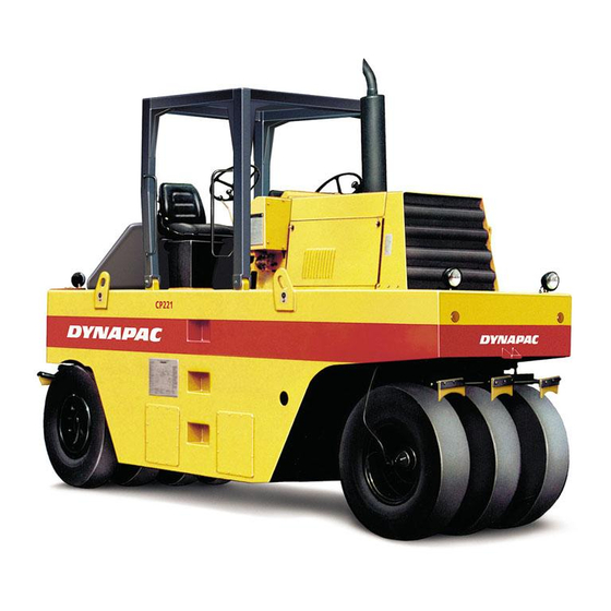
CP221 and 271 are heavy pneumatic rollers designed for the surface sealing and compacting of
asphalt together with steel-drum rollers. Due to their very high weight these pneumatic rollers are
also suitable for the compacting of subbases and base courses.
CP221 has three steered wheels at the front and four drive wheels
CP271 has five wheels at the front and four at the rear, mounted on a rigid axle.
Pneumatic rollers
CP221/271
Operation
O221EN5, September 2004
Diesel engine:
Cummins 4B4.5 - 99C
These instructions apply from:
CP221
PIN (S/N) *2262(BR)0600*
CP271
PIN (S/N) *2362(BR)0700*
at the rear, mounted on a rigid axle.
Reservation for changes.
Printed in Sweden.
Advertisement
Table of Contents


Need help?
Do you have a question about the CP221 and is the answer not in the manual?
Questions and answers