Table of Contents

Related Manuals for Dynapac CP275


Summary of Contents for Dynapac CP275
- Page 1 Instructions manual Operating & Maintenance 4812273203.pdf Rubber wheel roller CP275 (IIIA/T3) Diesel engine Cummins QSB4.5-C130 Serial number 10000509x0C003425 - Original instructions. Reservation for changes Printed in China...
-
Page 3: Table Of Contents
Contents Table of contents Instruction ............................. - Page 4 Contents .............................. 18 General ..........................19 Tightening torques ..........................21 Machine description ............................. 21 Identification ..................21 Product identification number on the frame ............................ 21 Machine plate ....................22 Explanation of 17PIN serial number ............................22 Engine plate ............................. 24 Safety decals .....................
- Page 5 Contents ..........................
- Page 6 Contents ....................61 After the FIRST 50 hours of operation ....................61 Every 50 hours of operation (Weekly) ..................... 62 Every 250 hours of operation (Monthly) ................62 Every 500 hours of operation (Every three months) ................63 Every 1000 hours of operation (Every six months) ....................
- Page 7 Contents ...................
- Page 8 Contents ......................101 Oil spray system (Optional) ......................102 Spray volume – Adjustment ..................102 Maintenance – Oil spray system (Optional) ......................... 102 Temporary cleaning ........................103 Air on the run (Optional) ......................... 104 Air charge and discharge ................... 104 Maintenance –...
-
Page 9: Instruction
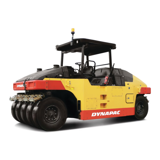
The machine Dynapac CP275 is a heavy rubber wheel roller in the 27 tones class, with a working width of 2370 mm. It has five guide wheels at the front, and four drive ... -
Page 10: Safety Information
Introduction Safety information It is recommended to at least train operators in handling and daily maintenance of the machine in accordance with the instruction manual. Passengers are not allowed on the machine, and ... -
Page 11: General
Introduction General This manual contains instructions machine operation and maintenance. The machine must be correctly maintained for maximal performance. The machine should be kept clean so that any ... - Page 12 Introduction 4812273203.pdf 2017-08-25 ...
-
Page 13: Safety - General Instructions
Safety – General instructions Safety - General instructions (Also read the safety manual) The operator must be familiar with the contents of the OPERATION section before starting the roller. ... - Page 14 Do not make any changes or modifications to the roller that could affect safety. Changes are only to be made after written approval has been given by Dynapac. Avoid using the roller before the hydraulic fluid has reached its normal working temperature.
-
Page 15: Safety - When Operating
Safety – When operating Safety – When operating Prevent persons from entering or remaining in the danger area, i.e. a distance of at least 7 m (23 ft) in all directions from operating machines. ... -
Page 16: Driving Near Edges
Safety – When operating Driving near edges When driving close to edges or holes, make sure that at least 1/4 of the outer tires are on the previously compacted material. At least 1/4 ... -
Page 17: Safety (Optional)
Safety (Optional) Safety (Optional) Air conditioning (Optional) system contains pressurized refrigerant. It is forbidden to release refrigerants into the atmosphere. Work on the refrigerant circuit is only to be carried out by authorized companies. - Page 18 Safety (Optional) 4812273203.pdf 2017-08-25 ...
-
Page 19: Special Instructions
Special instructions Special instructions Standard lubricants and other recommended oils and fluids Before leaving factory, systems components are filled with the oils and fluids specified in the lubricant specification. These are suitable for ... -
Page 20: High Pressure Cleaning
Special instructions High pressure cleaning Do not spray water directly onto electrical components or the instrument panels. Place a plastic bag over the fuel filler cap and secure with a rubber band. This is to avoid high pressure water ... - Page 21 Special instructions When fitting batteries, always connect the positive cable first. Dispose batteries environmentally friendly way. Batteries contain toxic lead. Do not use a quick-charger for charging ...
-
Page 22: Jumping Starting (24V)
Special instructions Jump starting (24V) Do not connect the negative cable to the negative terminal on the dead battery. A spark can ignite the oxy-hydrogen gas formed around the battery. -
Page 23: Technical Specifications
Technical specifications Technical specifications Noise level The noise levels are measured in accordance with the operational cycle described in GB16710 with operator seat in transport position. Guaranteed sound power level, LwA 108dB(A) ... -
Page 24: Technical Specifications - Dimensions
Technical specifications Technical specifications – Dimensions Dimensions Dimensions 4250 2370 3408 3100 14.2 5310 4812273203.pdf 2017-08-25 ... -
Page 25: Weights And Volumes
Technical specifications Weights and volumes Weights Weight without ballast 14500kg Weight with max ballast 30000kg Fluid volumes Hydraulic reservoir 80Liters 70.4Quart Diesel engine oil 9Liters 7.9Quart Coolant, diesel engine 20Liters 17.6Quart 320Liters 281.7Quart... -
Page 26: Working Capacity
Technical specifications Working capacity Compaction data Load: - Without ballast 1611kg - With max ballast 3333.3kg General Engine Manufacturer/Model Cummins QSB4.5-C130 Rated power (SEA J1995) 97kW 130hp Engine speed 2200 rpm Electric system Battery 24V (2x12V 74Ah) Alternator... -
Page 27: Tightening Torques
Technical specifications Tightening torque Tightening torque in Nm (lbf.ft) for oiled or dry bolts tightened with a torque wrench. Metric coarse screw thread, bright galvanized (fzb): STRENGTH CLASS: M - thread 8.8, Oiled 8.8, Dry 10.9, Oiled 10.9, Dry 12.9, Oiled 12.9, Dry 13,4 14,6 16,3... - Page 28 Technical specifications ROPS - bolts Bolt dimensions: M22 (PN 4812266655) Strength class: 10.9 Tightening torque: 786 Nm Hydraulic system Opening pressure Drive system 42,0 Charge system Control system 16,0 Fan drive 12,5 Brake release ...
-
Page 29: Machine Description
Machine description Machine description Identification Production identification number on the frame The machine's PIN (product identification number) is punched on the right edge of the frame (1). This number is the same number as the machine plate's PIN (serial number). -
Page 30: Explanation Of 17Pin Serial Number
Machine description Explanation of 17PIN serial number A= Manufacturer B= Family/Model C= Check letter D= No coding E= Production unit F= Serial number D, E, F would be useful when ordering spare parts ... - Page 31 Machine description Warning, crush zone 4700903422 Warning, rotating engine 4700903423 components Warning, burning hot surface 4700903424 Battery voltage 4700393959 Warning, instruction manual 4700903459 Water tank 4700991657 Hoisting plate 4700904870 Warning, high pressure fluid 4700397286 Tire pressure 4700374765...
-
Page 32: Safety Decals
Machine description Safety decals Always make sure that all safety decals are completely legible, and remove dirt or order new decals if they have become illegible. Use the part number specified on each decal. ... - Page 33 Machine description 4700904165 Warning - Toxic gas Read the instruction manual. 4700397286 Warning - High pressure fluid Make sure to drain the pressure in the accumulators before opening the hydraulic system. ...
- Page 34 Machine description 4812273203.pdf 2017-08-25 ...
-
Page 35: Locations - Control Panel And Controls
Machine description Locations - Control panel and controls Driving lights switch Working lights switch Rotation beacon switch Parking brake Control indicator (left) Horn Steering indicator (Left) Start switch Manual/Automatic water sprinkler Water/Oil sprinkler selector Oil/Water sprinkle time control Manual/Automatic oil sprinkler Direction indicator (Right) -
Page 36: Locations & Control, Cab
Machine description Location & control, cab 4812273203.pdf 2017-08-25 ... -
Page 37: Function Description Of Instruments And Controls In The Cab
Machine description Function description of instruments and controls in the cab Designation Symbol Function Turn to the right to increase heating. Heater control Turn to the left to reduce heating. In the left position, the fan is off. Ventilation fan, switch Turning the knob to the right increases the volume of air entering the cab. -
Page 38: Using The Cab Controls
Machine description Using the cab controls Defroster To quickly remove ice or mist, make sure that only the front and rear air nozzles are open. Turn the heater and fan dial (1 and 2) to max. ... -
Page 39: Electrical System
Machine description Electrical system The machine's main switchbox (fig1.) is located on the rear of the operator platform. There is a plastic cover over the switchbox and fuses. On the plastic cover there is a 24V socket. ... -
Page 40: Fuse
Machine description Fuse The figure shows the position of the fuses. The table in below gives fuse amperage and function. Fig. Fuse panel FUSE BOX1 FUSE BOX2 FU2: Power supply ECU FU8: Sprinkler shift FU3: Power supply ECU FU9: Oil/water sprinkler speed... -
Page 41: Operation
Operation Operation Before starting Master switch – Switching on Remember to carry out daily maintenance. Refer to the maintenance instructions. The battery disconnector is located in the engine compartment, on the right side of engine parts. ... -
Page 42: Before Starting
Operation Before starting 1. Control panel and lights - Check Turn the ignition key (2) to “ON” position, neutral position indicator (5), parking indicator (4) and control indicator (1) or (3) on operator side are all activated. Make sure the parking brake button (7) is on “pressed”... -
Page 43: Parking Brake - Check
Operation Parking brake – Check 3. Parking brake - Check Check tire pressure for all tires ensure the pressure accuracy. Check the “tire pressure gauge” (2) (option) on the control panel, move the manual pressure control valve (1) in the middle, move it upward to increase pressure, downward to decrease pressure. -
Page 44: Operator Position
Operation Operator position If a ROPS (Roll Over Protective Structure) or a cab is fitted to the roller, always wear the seat belt provided and wear a protective helmet. Replace the seat belt if it shows signs of wear or has been subjected to high levels of force. -
Page 45: Operating The Roller
Operation Operating the roller Under circumstances machine to be operated from the ground. The operator must be seated inside the machine during all operation. Check that the steering is working correctly by turning the steering wheel once to the right and once to the left while the roller is stationary. -
Page 46: Operating On A Slope
Operation Operating on a slope Under circumstances machine to be operated from the ground. The operator must be seated inside the machine during all operation. When transporting on steep ground (downward ... -
Page 47: Checking The Treads On The Tires
Operation Checking the treads on the tires Inspect the tire treads from time to time to ensure no asphalt has stuck to the tires. This can occur before the tires are sufficiently warm. ... -
Page 48: Ballast Box
Operation Ballast box Fig. Ballast box cover 1. Top left cover 2. Rear left cover 3. Top right cover 4. Rear right cover Increase ballast from both side of the frame ... -
Page 49: Driving (Ground Pressure)
Operation Driving (Ground Pressure) Ground pressure The contact surface of the tire can be changed by means of tire pressure. High tire pressure gives a smaller contact surface (1). Low tire pressure gives a larger contact surface (2). -
Page 50: Low Tire Pressure - 380Kpa (55 Psi)
Operation Tire inflation pressure/kPa Operating kg/tire 300 400 500 600 700 800 mass Average contact pressure/kPa 14000 1550 327 350 373 397 420 445 18000 2020 357.5 381 406 430 452.5 475 22500 2500 377.5 410 437.5 462.5 ... -
Page 51: Normal Tire Pressure - 510Kpa (70 Psi)
Operation Normal tire pressure – 510 kPa (70 psi) Used for degradation session. Fig. Normal ground pressure High tire pressure – 780 kPa (110 psi) The higher the tire pressure, the greater the pressure on the contact surface due to smaller contact surface. -
Page 52: Interlock/Emergency Stop/Parking Brake - Check
Operation Interlock/Emergency stop/Parking brake – Check The interlock, emergency stop and parking brake must be checked daily before operating. A function check of the interlock and emergency stop requires a restart. ... -
Page 53: Emergency Braking
Operation Emergency braking The brake pedal is normally used to emergency brake. When Forward/Reverse lever back to Neutral position, apply the brake pedal for emergency brake; When Forward/Reverse lever does not back to Neutral position, then apply the brake pedal would lead Diesel engine ... -
Page 54: Master Switch
Operation Master switch Before leaving the roller for the day, switch the master switch (1) to the disconnected position and remove the handle. This will prevent battery discharging and will also make it difficult for unauthorized persons to start ... -
Page 55: Long-Term Parking
Long-term parking Long-term parking The following instructions should be followed when long term parking (more than one month). These measures apply when parking for a period of up to 6 months. ... - Page 56 Long-term parking Watering system * Empty the water tank and all hoses of water. Empty the filter housing and the water pump. Undo all sprinkler nozzles. See maintenance sections for "Watering system – ...
-
Page 57: Miscellaneous
Miscellaneous Miscellaneous Lifting Weight: refer to the hoisting plate on Lifting the roller the r oller Ensure that the front wheels are parallel with the frame before the roller is lifted. Place the lifting chains in the lifting eyes and make sure that no parts are damaged by the chains when lifting. -
Page 58: Roller Prepare For Transport
Miscellaneous The machine must only be lifted with a jack, or the like, positioned as per the markings. The frame is reinforced at these points to withstand the tension. Lifting at any other place can result in damage to ... - Page 59 Miscellaneous When engine or pump damage could not be repaired, roller need to be towed by towing vehicle park to safe place waiting for repairing. Firstly, rotate the ball valve (1) handle clockwise 90°C, switch the oil-way, then rotate the hand pump handle (2) to hydraulic oil output (the handle rotation direction is the same as hydraulic pipeline connections);...
-
Page 60: Towing The Roller
See table below for maximum permitted pulling force for machine model. Fig. Towing Model CP275 92,700 Reverse the towing preparations made to the hydraulic pump and/or the motor. -
Page 61: Operating Instructions - Summary
Operating instructions - summary Operating instructions - Summary 1. Follow the SAFETY INSTRUCTIONS specified in the Safety Manual. 2. Make sure that all instructions in the MAINTENANCE section are followed. 3. Turn the master switch to the ON position. 4. - Page 62 Operating instructions - summary ...
-
Page 63: Preventive Maintenance
Preventive maintenance Preventive maintenance Complete maintenance is necessary for the machine to function satisfactorily and at the lowest possible cost. The Maintenance section includes the periodic maintenance that must be carried out on the ... - Page 64 Preventive maintenance 4812273203.pdf 2017-08-25 ...
-
Page 65: Maintenance - Lubricants And Symbols
Shell Tellus T100 or equivalent GREASE Shell Retinax LX2, or equivalent Air temperature 0°C - + 40°C (32°F - 104°F) TRANSMISSION OIL Dynapac Gear Oil 300 or equivalent FUEL See engine manual GlycoShell or equivalent (mixed 50/50 with water) COOLANT Prevents freezing to around -37°C... - Page 66 Maintenance – Lubricants and symbols ...
-
Page 67: Maintenance - Maintenance Schedules
Maintenance – Maintenance schedule Maintenance - Maintenance schedule Service and maintenance points Engine oil Air cleaner Lower pivot bearing Oil filter Refueling Upper pivot bearing Fuel filter Scraper Pivot bearing Hydraulic filter Water tank, filling Driving axle Hydraulic fluid level... -
Page 68: General
Maintenance –Maintenance schedule General ... -
Page 69: After The First 50 Hours Of Operation
Maintenance – Maintenance schedule After the FIRST 50 hours of operation Refer to the contents to find the page number of the sections referred to! Pos. in Action Comment 1, 2 Change the engine oil and oil filter Refer to the engine manual Change the fuel filter Refer to the engine manual... -
Page 70: Every 250 Hours Of Operation (Monthly)
Maintenance –Maintenance schedule Every 250 hours of operation (Monthly) ... -
Page 71: Every 1000 Hours Of Operation (Every Six Months)
Maintenance – Maintenance schedule Drain air tank Retighten wheel nuts Check bolted joints Every 1000 hours of operation (Every six months) Refer to the contents to find the page number of the sections referred to! ... -
Page 72: Every 2000 Hours Of Operation (Yearly)
Maintenance –Maintenance schedule Every 2000 hours of operation (Yearly) ... -
Page 73: Maintenance - 10H
Maintenance – 10h Maintenance – 10h Park the roller on a level surface. When checking and making adjustments to the roller, switch the engine off and make sure the ... -
Page 74: Hydraulic Reservoir - Check Fluid Level
Maintenance – 10h Hydraulic reservoir - Check fluid level The filler pipe and sight glass are on the left side of the fan cover in the engine compartment. Place the roller on a level surface and check that the oil level is between the max and min markings. -
Page 75: Fuel Tank - Refueling
Maintenance – 10h Fuel tank – Refueling Never refuel while the engine is running. Do not smoke and avoid spilling fuel. The filler pipe and tank cap are behind the operator platform on the left side of the frame. -
Page 76: Wheel Scrapers Control
Maintenance – 10h Wheel scrapers Control Check that the tires and scrapers are worn evenly. If there is uneven wear on the scraper, release the adjusting screw (3) on the back of the scraper attachment. -
Page 77: Water Tank, Std - Filling
Maintenance – 10h Water tank, Std – Filling There are two filler caps on the top of the tank. Unscrew the tank cap (1) and fill with clean water. Do not remover the strainer. ... -
Page 78: Sprinkler System
Maintenance – 10h Sprinkler system Cleaning of sprinkler nozzle 1 Dismantle the blocked nozzle by hand. 2 Blow the nozzle and fine filter (1) clean using compressed air. Alternatively, fit replacement parts and clean the blocked parts later on. -
Page 79: Sprinkler System - Freeze Risk
Maintenance – 10h Sprinkler system – Freeze risk Preventive measures when there is a risk of freezing. Draining the system Close the valve (1). Separate the hose (2). Open the coarse filter (3). Loosen the intake to the pump by moving the plastic clamp to the left and pulling the white plastic adapter from the pump housing. -
Page 80: Brake Fluid Level - Check
Maintenance – 10h Brake fluid level – Check Check every day that the fluid level is between the max/min marks. Open the containers, which positioned on both front and rear of the frame. Top up with brake fluid to the max mark on the Fig. -
Page 81: Maintenance - 50H
Maintenance – 50h Maintenance – 50h Park the roller on a level surface. When checking and making adjustments to the roller, switch the engine off and make sure the ... -
Page 82: Hydraulic Fluid Cooler - Checking - Cleaning
Maintenance – 50h Hydraulic fluid cooler - Checking - Cleaning The water and hydraulic fluid coolers are accessible when the cooler grill is removed. Make sure that the air flow through the cooler is unobstructed. -
Page 83: Fuel Filter - Draining
Maintenance – 50h Fuel filter – Draining Unscrew the drain plug (1) at the bottom of the fuel filter. With the aid of the secondary hand-operated pump, make certain that all sediment comes out. See Cummins service manual. -
Page 84: Air Conditioning (Optional) - Drying Filter - Inspection
Maintenance – 50h Air conditioning (Optional) – Drying filter – Inspection Park the roller on a level surface, chock the wheels and the set the Forward/Reverse lever in the Neutral position. With the unit in operation, check using the sight glass (1) that bubbles are not visible on the drying filter. -
Page 85: Air Conditioning (Optional) - Overhaul
Maintenance – 50h Air conditioning (Optional) – Overhaul Regular inspection and maintenance is necessary to ensure satisfactory long-term operation. Clean all dust from the condenser element (1) using compressed air. Blow from above downwards. -
Page 86: Upper/Lower Pivot Bearing - Lubrication
Maintenance – 50h Upper/Lower Pivot bearing – Lubrication Lubricate nipple (1) on upper pivot bearing and nipples (2) on lower pivot bearing with five pump stokes from hand-operated grease gun. Use grease as specified in the lubricant specification. ... -
Page 87: Draining Of Air Reservoir
Maintenance – 50h Draining of air reservoir When the machine works in humid environment, the air reservoirs (2) need to drain every day. Press the drainage valve (3) upwards until there is no water in the air reservoirs (2). -
Page 88: Tires - Tire Pressure
Maintenance – 50h Tires – Tire pressure Check the tire pressure with a pressure gauge. Make sure that the tires have the same pressure. Recommended pressure: See Technical Specifications. The figure shows the position of the air valve on the ... -
Page 89: Maintenance - 250H
Maintenance – 250h Maintenance – 250h Park the roller on a level surface. When checking and making adjustments to the roller, switch the engine off and make sure the ... -
Page 90: Diesel Engine - Oil Change
Maintenance – 250h Diesel engine – Oil change The engine's oil drain plug is delivered under the rotatory support on the front of the frame through the rubber tube. Unscrew the drain plug the engine oil could be changed. -
Page 91: The Engine Fuel Filter - Changing/Cleaning
Maintenance – 250h The engine fuel filter - Changing Fuel filter is located on the left side in the engine compartment. Unscrew the old one with special spanner, and then replace with the new one. ... -
Page 92: Oil - Water Separator - Draining
Maintenance – 250h Oil – water separator – Draining Unscrew the drain plug (1) at the bottom of the oil-water separator. Tighten the drain plug as soon as uncontaminated fuel runs out. ... -
Page 93: Battery - Check Condition
Maintenance – 250h Battery – Check condition The batteries are sealed and maintenance-free. Make sure there is no open flame in the vicinity when checking the electrolyte level. Explosive gas in formed when the alternator ... -
Page 94: Driven Chain Maintenance
Maintenance – 250h Driven chain maintenance Normally, when the machine has worked over 250 hours, the driven chain needs maintaining. Loosen the bolts (1) and remove the cover (2), use the oilcan to instill gear oil on the driven chain (3); When the machine moves forward one third circle of the wheel, stop and instill again. -
Page 95: Driving Gear - Check Oil Level
Maintenance – 250h Driving gear – Check oil level Move the machine so that the level plug (3) is in horizontal position. Wipe clean the area around the level plug (3) and then undo the plug. - Page 96 Maintenance – 250h 4812273203.pdf 2017-08-25 ...
-
Page 97: Maintenance - 500H
Maintenance – 500h Maintenance – 500h Park the roller on a level surface. When checking and making adjustments to the roller, switch the engine off and make sure the ... - Page 98 Maintenance – 500h 4812273203.pdf 2017-08-25 ...
-
Page 99: Maintenance - 1000H
Maintenance – 1000h Maintenance – 1000h Park the roller on a level surface. When checking and making adjustments to the roller, switch the engine off and make sure the ... -
Page 100: Hydraulic Filter Change
Maintenance – 1000h Hydraulic filter Change The hydraulic filters are located on the left side in the engine compartment, behind the battery disconnector. Remove the filter and hand in to waste disposal station. -
Page 101: Cab - Fresh Air Filter - Replacing
Maintenance – 1000h Fresh air filter - Replacing There is one fresh air filter (1), placed on the front of the cab. Remove the protective cover. Undo the screws (2) and remove the complete holder. ... -
Page 102: Drive Gear - Replenishing The Oil
Maintenance – 1000h Driving gear - Replenishing the oil Move the machine so that the filler hole is correctly positioned. The hole should be just over the horizontal position to simplify filling. Unscrew the filler plug (2). -
Page 103: Maintenance - 2000H
Maintenance – 2000h Maintenance – 2000h Park the roller on a level surface. When checking and making adjustments to the roller, switch the engine off and make sure the ... -
Page 104: Hydraulic Reservoir - Fluid Change
Maintenance – 2000h Hydraulic reservoir - Fluid change Take great care when draining the hydraulic fluid. Wear protective gloves and goggles. Hydraulic reservoir’s drain plug is located on the left front side of the frame, under the hydraulic reservoir. Open the drain plug to run out oil inside the hydraulic ... -
Page 105: Water Tank - Cleaning
Maintenance – 2000h Water tank - Cleaning Clean the tank with water and a suitable detergent for plastic surfaces. Close the drain cock (1), fill with water and check for leaks. The water tank is made of plastic ... -
Page 106: Cab - Fresh Air Filter - Replacing
Maintenance – 2000h Cab – Fresh air filter – Replacing There is one fresh air filter (1), placed on the front of the cab. Remove the protective cover. Undo the screws (2) and remove the complete holder. Fig. -
Page 107: Drive Chain - Adjustment
Maintenance – 2000h Drive chain - Adjustment When the machine working over 2000 hours, it needs to adjust the drive chain so that the rear wheels can rotate freely. Loosen the lock nuts (2) on the adjusting bolt (1). Turn the adjusting bolt (1) while rotating the wheel until the increase in tension slows the wheel down. - Page 108 Maintenance – 2000h 4812273203.pdf 2017-08-25 ...
-
Page 109: Additional Instruction
Additional instruction Oil spray system Before starting Check the oil level of the tank, if the oil level warning LED is on please fill the “plant oil” Check the distance between the cover and tire’s surface (1) no less than 20 mm. -
Page 110: Spray Volume - Adjustment
Additional instruction Spray volume – Adjustment Oil spray volume can be adjusted through the valve (1). - Tighten to increase the volume; - Unscrew to decrease the volume. Since the oil viscosity has a big changing with ... -
Page 111: Air On The Run (Optional)
Additional instruction Air on the run (Optional) Before starting Check the air pressure from the air gauge on instrument panel, it should be in 380kPa – 780kPa. (fig1). Fig 1. Instrument panel – Air gauge Check the air valve status: In general, the air valves are closed when the roller is shipped out from factory. -
Page 112: Air Charge And Discharge
Additional instruction - Tighten the lock nut. Fig 6. Close the gas valve. Loosen the lock nut of the air valve using a wrench, screw out the valve element about 10mm with a screw driver, and tighten the lock nut. - Page 113 Additional instruction Every 3 months / 250 hours Check the air pipes of the system; Check the air valve. Long-term parking When long-term parking (more than one week), please ...
- Page 114 Additional instruction 4812273203.pdf 2017-08-25 ...
-
Page 115: Disposal
Disposal Disposal Correctly sorted disposal must be carried out after replacing wear and spare parts and after the machine has been withdraw from service (scrapped). materials must sorted correctly...
Need help?
Do you have a question about the CP275 and is the answer not in the manual?
Questions and answers