Sign In
Upload
Manuals
Brands
COBHAM Manuals
Antenna
SEA TEL 9711IMA-70
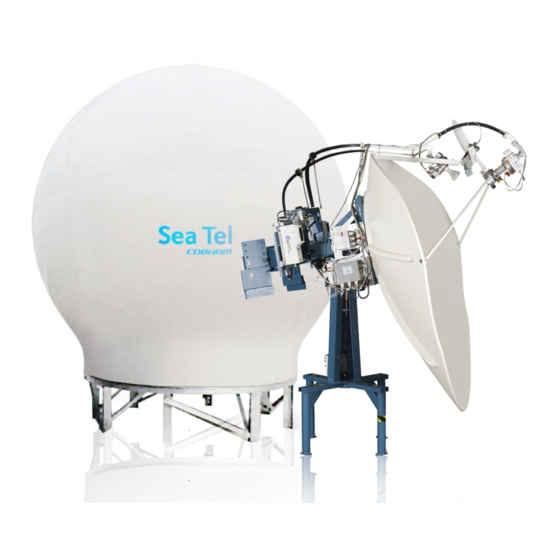
User Manuals: COBHAM SEA TEL 9711IMA-70 Antenna
Manuals and User Guides for COBHAM SEA TEL 9711IMA-70 Antenna. We have
1
COBHAM SEA TEL 9711IMA-70 Antenna manual available for free PDF download: Installation Manual
COBHAM SEA TEL 9711IMA-70 Installation Manual (178 pages)
Brand:
COBHAM
| Category:
Antenna
| Size: 13 MB
Table of Contents
Table of Contents
7
1 Introduction
11
General System Description
11
Purpose
11
Other Inputs to the 1.4. System Components
11
Dual Antenna Configuration
12
Dual Network Arbitrator
12
Automatic Beam Switching (Abs)
13
Openamip™, ROAM or VACP
13
Fcc Compliance
13
2 Site Survey
15
Site Selection Aboard the Ship
15
Antenna Shadowing (Blockage) and RF Interference
15
Mounting Foundation
16
Mounting on Deck or Deckhouse
16
ADE Mounting Considerations
16
Sizing of the Support Pedestal
16
Mounting Height and Fore-Aft Location
16
Mast Configurations
17
Vertical Masts
18
Raked Masts
18
Girder Masts
18
Truss Mast
19
Safe Access to the Ade
19
Below Decks Equipment Location
19
Cables
19
ADE/BDE Coaxial Cables
20
Antenna Power Cable
20
Air Conditioner Power Cable
20
ACU Power Cable/Outlet
20
Gyro Compass Cable
20
Grounding
20
3 Installation
21
General Cautions & Warnings
21
Preparation
21
Opening Your Crates
22
Location of Items Inside the Crates
22
Base Frame and Reflector Crate
22
Pedestal Crate
23
Radome Crate
24
Unpacking the Base Frame and Reflector Crate
25
Unpacking the Pedestal Crate
28
Unpacking the Radome Crate
30
Assembling the Ade
31
Preparing for Assembly of the ADE
31
Sub-Assemble the Base Frame Assembly
31
Marine Air Conditioner
32
Assembling the Lower Radome Panels
32
Sub-Assemble the Upper Panels of the 144" Radome Assembly
35
Sub-Assemble the Antenna Pedestal
38
Close the 144" Radome Assembly
42
Preparing to Hoist the Ade
43
Installing the Ade
44
Hoist the ADE
44
Connecting the ADE
44
Remove Stow Straps
45
ADE Final Checks
45
Installing the below Decks Equipment
45
3.10.1. General Cautions & Warnings
45
Connecting the BDE AC Power Cables
45
Media Xchange Point™ (MXP) Connections
45
3.10.4. Other BDE Connections
47
3.11. BDE Final Checks
47
3.11.1. Visual/Electrical Inspection
47
3.11.2. Electrical - Double Check Wiring Connections
47
Setup - Media Xchange Point™ (MXP)
48
4 Configuring a Computer for the Mxp
49
5 Setup - Ship's Gyro Compass
55
Setting the Gyro Type
55
If There Is no Ships Gyro Compass
55
6 Setup - Tracking Receiver - Vsat
57
Determining the if Tracking Frequency (Mhz)
57
Sat Skew
57
7 Setup - Azimuth Trim
59
8 Setup - Blockage & Rf Radiation Hazard Zones
61
Radiation Hazard and Blockage Mapping
61
Programming Instructions
62
9 Configuring the Satellite Modem Interface
65
Satellite Modem Interface
65
Reflector Setting
66
Modem Type Setting
66
Modem I/O Setting
66
Modem I/O - Custom Settings
67
Quick Reference: Common Modem Lock & Mute Settings
69
10 Setup - Targeting
71
Auto Trim
71
Manually Optimizing Targeting
72
11 Setup - Satellite Configuration
75
Searching Patterns
75
Default "Spiral" (Box) Search Pattern
75
Inclined Orbit Search Pattern
75
Sky Search Pattern
76
Tx Pol Select
76
Band Select
76
X-Pol / Co-Pol Select
76
Selecting/Configuring Your Satellite Configuration
76
12 Quick Start Operation
79
If Satellite Signal Is Found and Network Lock Is Achieved
79
If no Signal Is Found
79
If Satellite Signal Is Found but Network Lock Is NOT Achieved
81
T Otarget a Different Satellite
82
13 Optimizing Cross-Pol Isolation
85
Optimizing Cross -Pol Isolation
86
14 Installation Troubleshooting
87
14.1. Troubleshooting Ships Gyro Compass Problems
87
14.1.1. Step-By-Step
87
14.1.2. 1:1 Synchro
87
14.1.3. 360:1 Synchro
88
15 Maintenance
89
15.1. Warranty Information
89
15.2. Torque and Loctite Specifications
89
General Maintenance
90
Identifying the Linear/Circular Selectable Feed Assembly
90
Installing the Linear/Circular Selectable Feed Assembly
92
Field Repair & Calibration of the C-Band Circular/Linear Selectable Feed
94
Components of the Feed
95
Tools Required
95
PC Computer Setup (Progterm)
95
Circular Feed Drive Test Procedure
96
Linear Feed Drive Test Procedure
97
Circular Feed Calibration Procedure
97
Linear Feed Calibration Procedure
100
Circular Pot Replacement Procedure
103
Circular Motor Replacement Procedure
104
Circular Limit Switch Replacement Procedure
105
Linear Pot Replacement Procedure
105
Linear Motor Replacement Procedure
106
Linear Limit Switch Replacement Procedure
107
Balancing the Antenna
108
Fine Balance and Monitoring Motor Drive Torque
108
16 Stowing the Antenna
111
Installing the Stow Restraints
111
1 Ima-70 Technical Specifications
113
Above Decks Equipment
113
Below Decks Equipment
118
Regulatory Compliance
120
Cables
120
Antenna Control Cable (Provided from ACU-MUX)
120
Antenna Transmit & Receive if Coax Cables (Customer Furnished)
121
Multi-Conductor Cables (Customer Furnished)
121
AC Power Cable (Pedestal & Rf Equipment)
121
AC Power Cable (Optional Marine Air Conditioner)
121
Gyro Compass Interface Cable (Customer Furnished)
121
18 Drawings
123
9711Ima-70 M
123
Drawings
124
Advertisement
Advertisement
Related Products
COBHAM Sailor 900 VSAT
COBHAM SAILOR 900
COBHAM SAILOR 900 Ka
COBHAM SAILOR 900A VSAT
COBHAM SAILOR 900B VSAT
COBHAM Sea Tel
COBHAM Sea Tel 09 Series
COBHAM Sea Tel 4009-11
COBHAM Sea Tel 4009-17
COBHAM Sea Tel 4009-23
COBHAM Categories
Antenna
Marine Equipment
Radio
Touch terminals
Receiver
More COBHAM Manuals
Login
Sign In
OR
Sign in with Facebook
Sign in with Google
Upload manual
Upload from disk
Upload from URL