Table of Contents
Advertisement
Quick Links
Advertisement
Table of Contents

Related Manuals for Resol DeltaSol AL


Summary of Contents for Resol DeltaSol AL
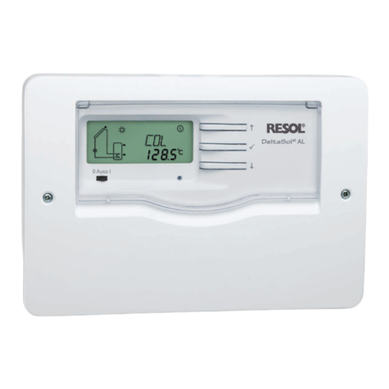
- Page 1 ® RESOL DeltaSol Mounting Connection Operation Troubleshooting Examples en-US/CA Manual Thank you for buying this RESOL product. Please read this manual carefully to get the best performance from this unit. Please keep this manual carefully. www.resol.com...
-
Page 2: Table Of Contents
DeltaSol ® Table of contents advice ................ 2 3.3 Slide switch ..............8 1. Overview .............. 3 3.4 Flashing codes ............... 8 2. installation ............4 4. Control parameters and display channels ..9 2.1 Mounting ................ 4 4.1 Channel overview ............9 2.2 Electrical connection .......... -
Page 3: Overview
• Energy metering • Function control • Solar operating hours counter • Housing with brandnew design • Intuitive operating concept • RESOL VBus ® • Energy-efficient through low standby power consumption included with the DeltaSol ® 1 x DeltaSol ®... -
Page 4: Installation
DeltaSol ® installation Mounting WaRning! Electric shock! Î always disconnect the con- crosshead troller from power supply screw before opening the housing! The unit must only be located in dry interior rooms. It is not suitable for installation in hazardous locations and should be protected against electromagnetic fields. -
Page 5: Electrical Connection
= ground terminal Attach flexible cables to the housing with the enclosed strain relief and the corresponding screws. Data communication / Bus The controller is equipped with the RESOL VBus for data ® transfer with and energy supply to external modules. Carry out the connection at the two terminals marked “VBus”... -
Page 6: Terminal Allocation
DeltaSol ® Terminal allocation Standard solar system with one tank, one pump and three sensors. Sensors S1 / S2 are also used for energy metering. Symbol Description collector sensor tank sensor base tank sensor top (optional) R1-A solar pump Operation Buttons for adjustment The controller is operated via the three push buttons next to the display. -
Page 7: System-Monitoring-Display
DeltaSol ® System-Monitoring-Display The system monitoring display consists of three blocks: channel display, tool bar and System-Screen. System-Monitoring-Display 3.2.1 Channel display The channel display consists of two lines. The upper line is an alpha-numeric 16-segment display (text display) for displaying channel names and menu items. In the lower 7-segment display, channel values and the adjustment pa- rameters are displayed. -
Page 8: Slide Switch
DeltaSol ® 3.2.3 System-Screen The system screen shows the system. The screen consists of several system component symbols, which are – depend- ing on the current status of the system – either flashing, permanently shown or “hidden”. System-Screen Sensor Tank sensor top Collector Pump Tank heat exchanger... -
Page 9: Control Parameters And Display Channels
DeltaSol ® Control parameters and display channels Channel overview note: Only if the temperature sensor is connected, will S3 be displayed! Channel Designation Page Channel Designation Page temperature collector option collector cooling collector temperature tank maximum temperature collector temperature sensor 3 option minimum limitation operating hours relay collector... - Page 10 DeltaSol ® Operating hours counter h P: The operating hours counter accumulates the solar opera- operating hours counter ting hours (h P) of the relay. Full hours are displayed. display channel The accumulated operating hours can be set back to zero. As soon as one operating hours channel is selected, the symbol is displayed.
- Page 11 DeltaSol ® ∆T -regulation DT O: If the switch-on difference (DT O) is reached, the pump switch-on temperature dif- is activated. If the temperature difference falls below the ference adjusted switch-off temperature difference (DT F) the adjustment range: controller switches off. 1.0 ...
- Page 12 DeltaSol ® if the OREC option is additionally activated: If the tank temperature is higher than the maximum tank temperature (S MX) and if the collector temperature is at least 5 K (10 °Ra) below the tank temperature, the solar system remains activated until the tank is cooled down below the adjusted maximum temperature (S MX) via the collector and the pipework.
- Page 13 DeltaSol ® Evacuated tube collector function O TC: If the controller detects an increase in collector tempera- tube collector function ture by 2 K (4 °Ra) compared to the previously stored col- adjustment range: OFF / ON lector temperature, the solar pump will be switched-on for factory setting: OFF about 30 seconds in order to detect the fluid temperature.
-
Page 14: Troubleshooting
DeltaSol ® Troubleshooting If a malfunction occurs, an error code will be indicated on the display by means of symbols (see chap. 3.2.2). Fuse holder Symbols Operating control lamp The controller is protected by a fuse. The fuse holder (which Operating control lamp flashes red. -
Page 15: 5.1 Various
DeltaSol ® 5.1 Various Pump is overheated, but no heat transfer from the collec- Pump starts for a short moment, switches on/off tor to the tank, flow and return have the same tempera- again, etc. ture; perhaps also bubbles in the pipes Air in the system? Is the temperature differ- Vent the system;... - Page 16 DeltaSol ® Tanks cool down at night. Check the non-return Further pumps which are valve in warm water cir- connected to the solar culation – o.k.? tank must also be che- cked. Does the collector circuit pump run during the night? Check controller.
-
Page 17: Accessories
RESOL SD3 Article no.: 180 004 93 Large Display ga3 The RESOL Large Display GA3 is designed for simple connection to RESOL controllers via the RESOL VBus ® . It is used for visualizing the data issued by the controller: collector and tank temperature as well as heat quantity produced in the solar system. - Page 18 DeltaSol ® notes...
- Page 19 DeltaSol ® notes...
-
Page 20: Copyright
Another use outside the copyright requires please note: Your own calculations and plans, under con sider- the approval of RESOL - Elektronische Regelungen GmbH. ation of the current standards should only be basis for your This especially applies for copies, translations, micro- projects.
Need help?
Do you have a question about the DeltaSol AL and is the answer not in the manual?
Questions and answers