Table of Contents
Advertisement
Quick Links
701-902 SmartSeries
Confidentiality Notice .....................................................................................................................1
General Information .......................................................................................................................1
Product Usage.......................................................................................................................................... 1
Features and Options .............................................................................................................................. 1
External Components ............................................................................................................................. 2
Internal Components .............................................................................................................................. 2
Block Diagram ......................................................................................................................................... 3
Interfaces ................................................................................................................................................. 4
Installation ......................................................................................................................................4
Minimum Level Adjustment ................................................................................................................. 4
Offset Level Adjustment ....................................................................................................................... 5
VLC (Volume Level Control) Adjustment (ADVANCE Systems only) .............................................. 5
Internal Adjustments .............................................................................................................................. 6
Station Address ..................................................................................................................................... 6
Handset Receiver Volume .................................................................................................................... 6
Sidetone Volume ................................................................................................................................... 6
External Adjustments ............................................................................................................................. 6
Minimum Level Adjustment ................................................................................................................. 7
Offset Level Adjustment ....................................................................................................................... 7
VLC (Volume Level Control) Adjustment (ADVANCE Systems only) .............................................. 7
Internal Adjustments .............................................................................................................................. 8
Station Address ..................................................................................................................................... 8
Handset Receiver Volume .................................................................................................................... 8
Sidetone Volume ................................................................................................................................... 8
Operation .........................................................................................................................................9
Page/Party Operation ............................................................................................................................. 9
Page Announcement ............................................................................................................................. 9
Party-Line Conversation ....................................................................................................................... 9
ADVANCE System Operation ............................................................................................................. 10
Page Confirmation Tone ..................................................................................................................... 10
Page and Party Line Operation ........................................................................................................... 10
Optional Features .................................................................................................................................. 10
Maintenance ..................................................................................................................................11
Service and Spare Parts ........................................................................................................................ 11
GAI-TRONICS 3030 KUTZTOWN RD. READING, PA 19605 USA
610-777-1374 ◼ 800-492-1212 ◼ Fax: 610-796-5954
V
ISIT WWW
G A I - T R O N I C S
A H U B B E L L C O M P A N Y
Amplifier
T
A B L E O F
.
-
.
GAI
TRONICS
COM FOR PRODUCT LITERATURE AND MANUALS
®
Handset/Speaker
®
C
O N T E N T S
Pub. 42004-658L2H
Advertisement
Table of Contents

Related Manuals for Hubbell GAI-TRONICS SmartSeries 701-902


Summary of Contents for Hubbell GAI-TRONICS SmartSeries 701-902
-
Page 1: Table Of Contents
Pub. 42004-658L2H G A I - T R O N I C S ® A H U B B E L L C O M P A N Y 701-902 SmartSeries Handset/Speaker ® Amplifier A B L E O F O N T E N T S Confidentiality Notice ........................1 General Information ........................1... - Page 2 Table of Contents Pub. 42004-658L2H Fuses ............................... 12 Troubleshooting ............................ 12 How to Diagnose Assembly Faults ....................... 13 Specifications ..........................15 Electrical ..............................15 Speaker Amplifier ..........................15 SmartVolume™............................. 15 Handset Amplifier ..........................15 Mechanical ............................. 15 Environmental ............................15 Approvals ............................15 GAI-TRONICS 3030 KUTZTOWN RD.
-
Page 3: Confidentiality Notice
Pub. 42004-658L2H G A I - T R O N I C S ® A H U B B E L L C O M P A N Y 701-902 SmartSeries Handset/Speaker ® Amplifier Confidentiality Notice This manual is provided solely as an installation, operation, and maintenance guide and contains sensitive business and technical information that is confidential and proprietary to GAI-Tronics. -
Page 4: External Components
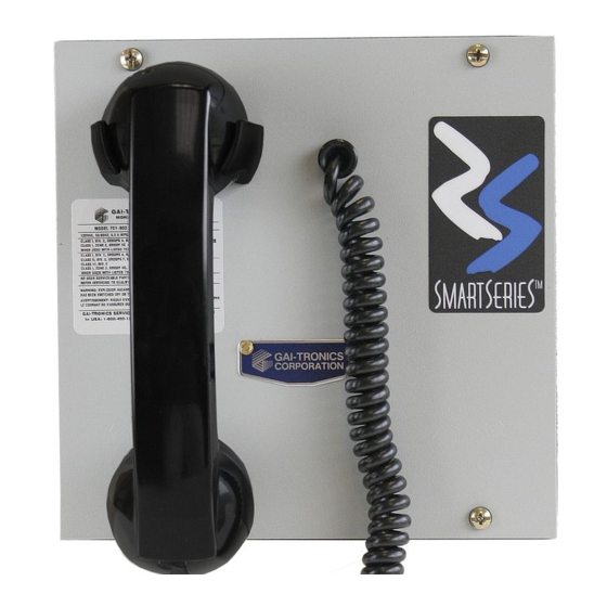
Pub. 42004-658L2H ® 701-902 SmartSeries Handset/Speaker Amplifier Page 2 of 15 External Components The handset/speaker amplifier assembly includes a handset and cradle (see Figure 1). A hookswitch (magnetic reed switch) in the cradle signals the appropriate off-hook status to the microcontroller in the assembly when the handset is removed from or placed in the cradle. -
Page 5: Block Diagram
Pub. 42004-658L2H ® 701-902 SmartSeries Handset/Speaker Amplifier Page 3 of 15 Figure 2. Side View Block Diagram Connector P1 on the back of the speaker amplifier/power supply PCBA plugs into a socket in an enclosure connected to the system cable, accessing the Page/Party lines and ac power. The speaker amplifier/power supply PCBA contains the low voltage power supplies and the speaker amplifier circuitry. -
Page 6: Interfaces
Pub. 42004-658L2H ® 701-902 SmartSeries Handset/Speaker Amplifier Page 4 of 15 Interfaces The assembly connects to the system cable, an external loudspeaker, and any auxiliary devices via the 16- pin connector, P1, located on the speaker amplifier/power supply PCBA. Connector J2, on the bottom of the speaker amplifier/power supply PCBA, connects to optional devices such as a SmartSeries RTU (remote terminal unit) installed in specially designed enclosures. -
Page 7: Offset Level Adjustment
Pub. 42004-658L2H ® 701-902 SmartSeries Handset/Speaker Amplifier Page 5 of 15 3. Turn the user adjustment control fully counterclockwise. 4. Listen for a single beep from the speaker indicating the speaker amplifier is in the minimum level adjustment mode. If the page line is in use immediately after the beep tone is heard: use the page signal as the reference to adjust the speaker volume level. -
Page 8: Internal Adjustments
Pub. 42004-658L2H ® 701-902 SmartSeries Handset/Speaker Amplifier Page 6 of 15 Internal Adjustments The station address, sidetone volume level, and handset receiver volume level are adjusted internally (see Figure 2). Turn the control clockwise to increase the volume or threshold; turn it counterclockwise to decrease the volume or threshold. -
Page 9: Minimum Level Adjustment
Pub. 42004-658L2H ® 701-902 SmartSeries Handset/Speaker Amplifier Page 7 of 15 Minimum Level Adjustment The factory default setting for minimum level is 4.0 watts nominal. To set the minimum amplifier output level: 5. Loosen the two screws on the GAI-Tronics nameplate and rotate it counterclockwise. 6. -
Page 10: Internal Adjustments
Pub. 42004-658L2H ® 701-902 SmartSeries Handset/Speaker Amplifier Page 8 of 15 15. Turn the user adjustment control fully counterclockwise during the page. 16. Listen for two beep tones through the page speaker indicating VLC adjustment mode is active. 17. Turn the user adjustment control to the desired speaker level using the live paging signal to adjust the level. -
Page 11: Operation
Pub. 42004-658L2H ® 701-902 SmartSeries Handset/Speaker Amplifier Page 9 of 15 3. Connect the assembly to the enclosure using a No. 10440-002 maintenance cable between P1 on the assembly and J1 on the enclosure. 4. Locate and adjust the control on the appropriate PCBA. 5. -
Page 12: Advance System Operation
Pub. 42004-658L2H ® 701-902 SmartSeries Handset/Speaker Amplifier Page 10 of 15 ADVANCE System Operation Page Confirmation Tone A page-confirmation tone is audible in the handset receiver when the page switch is depressed. Do not talk until the tone ceases. The page request has been granted by the system control cabinet when the tone ceases. -
Page 13: Maintenance
Pub. 42004-658L2H ® 701-902 SmartSeries Handset/Speaker Amplifier Page 11 of 15 Maintenance Regular inspection and a good preventive maintenance program will increase the reliability of your GAI-Tronics station. The GAI-Tronics Field Service Department can formulate a service contract suited to your facility’s specific need for preventive maintenance. WARNING —Remove all power from the station before performing any preventive maintenance steps. -
Page 14: Fuses
Pub. 42004-658L2H ® 701-902 SmartSeries Handset/Speaker Amplifier Page 12 of 15 Fuses There are three replaceable fuses (F1, F2, and F3) mounted on the speaker amplifier/power supply PCBA (see Figure 2). • Fuse F1 protects the low voltage power supply circuits. Replace with GAI-Tronics part number 51801-027. -
Page 15: How To Diagnose Assembly Faults
Pub. 42004-658L2H ® 701-902 SmartSeries Handset/Speaker Amplifier Page 13 of 15 Problem Possible Solution • Check within the enclosure for a purple wire on terminal 7: this is the Feedback during page default setting for local speaker mute. If the wire is on terminal 8, only then the speaker is unmuted and may be causing feedback. - Page 16 Pub. 42004-658L2H ® 701-902 SmartSeries Handset/Speaker Amplifier Page 14 of 15 Fault Message Cause and Effect Possible Solution • Replace the Supervised Audio Cause—The station failed its internal health Handset/FSK/P PCBA. Path check of the Handset/FSK/P PCBA. • Replace the Speaker Effect—The station disables the handset Handset Amplifier/Power Supply...
-
Page 17: Specifications
Pub. 42004-658L2H ® 701-902 SmartSeries Handset/Speaker Amplifier Page 15 of 15 Specifications Electrical Supply voltage ................90–140 V ac (120 V ac nominal), 50/60 Hz Power consumed @ nominal ac ......zero/maximum signal (12 W): 15 VA, 9 W/59 VA, 32 W Speaker Amplifier Output .................. -
Page 18: Return Policy
Warranty Equipment. GAI-Tronics warrants for a period of one (1) year from the date of shipment, that any GAI-Tronics equipment supplied hereunder shall be free of defects in material and workmanship, shall comply with the then-current product specifications and product literature, and if applicable, shall be fit for the purpose specified in the agreed upon quotation or proposal document.
Need help?
Do you have a question about the GAI-TRONICS SmartSeries 701-902 and is the answer not in the manual?
Questions and answers