Table of Contents
Advertisement
Quick Links
Advertisement
Table of Contents

Related Manuals for Fluke 1550C


Summary of Contents for Fluke 1550C
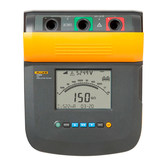
- Page 1 1550C/1555 Insulation Tester Calibration Manual September 2010 Rev. 1, 6/18 © 2010-2018 Fluke Corporation. All rights reserved. Specifications are subject to change without notice. All product names are trademarks of their respective companies.
- Page 2 Fluke authorized resellers shall extend this warranty on new and unused products to end-user customers only but have no authority to extend a greater or different warranty on behalf of Fluke. Warranty support is available only if product is purchased through a Fluke authorized sales outlet or Buyer has paid the applicable international price. Fluke reserves the right to invoice Buyer for importation costs of repair/replacement parts when product purchased in one country is submitted for repair in another country.
-
Page 3: Table Of Contents
Table of Contents Title Page Introduction ......................1 How to Contact Fluke ..................2 Safety Information ....................2 Symbols ......................5 Required Equipment ..................6 Performance Test Procedures ................7 IR Port Verification Test ................. 7 Button Test ....................8 Display Test .................... - Page 4 1550C/1555 Calibration Manual...
-
Page 5: Introduction
• Read all safety information before you use or service the product. The Calibration Manual for the 1550C/1555 Insulation Tester (the Product) provides the following information. • Fluke Contact Information •... -
Page 6: How To Contact Fluke
1550C/1555 Calibration Manual How to Contact Fluke To contact Fluke, use one of these telephone numbers: • To contact Fluke, use one of these telephone numbers: • USA: 1-800-760-4523 • Canada: 1-800-36-FLUKE (1-800-363-5853) • Europe: +31 402-675-200 • Japan: +81-3-6714-3114 •... - Page 7 Insulation Tester Safety Information • Do not exceed the Measurement Category (CAT) rating of the lowest rated individual component of a Product, probe, or accessory. • Do not use in CAT III or CAT IV environments without the protective cap installed on test probe. The protective cap decreases the exposed probe metal to <4 mm.
- Page 8 1550C/1555 Calibration Manual • Remove all power from the circuit under test and discharge circuit capacitance before testing resistance or capacitor with the tester. • Results of measurement can be adversely affected by the impedances of additional operating circuits connected in parallel or by transient currents.
-
Page 9: Symbols
Insulation Tester Symbols Symbols Table 1 is a list of symbols used on the Product or in this manual. Table 1. Symbols Symbol Meaning Consult user documentation. WARNING. RISK OF DANGER. WARNING. HAZARDOUS VOLTAGE. Risk of electric shock. Earth ... -
Page 10: Required Equipment
Can use (3) each, 0.033 μF, 2 kV capacitors in series and (8) each, 8 μF, 450 V capacitors in series to obtain required values. The 0.033 μF capacitors should have a 33 MΩ bleeder resistor across each capacitor. The 8 μF capacitors should have a 15 MΩ bleeder resistor across each capacitor. Available from www.fluke.com under 1550C/1555 Product Information. -
Page 11: Performance Test Procedures
If the UUT fails any of the performance test steps, repair or adjustment is needed. Refer to How to Contact Fluke for service information. IR Port Verification Test To verify operation of the IR Communications Port: 1. -
Page 12: Button Test
1550C/1555 Calibration Manual Button Test Use the pushbuttons to control the product, view test results, and scroll through chosen test results. Table 3 is a list of the pushbuttons and their functionality. Table 3. Pushbuttons FUNCTION ENTER TEST ghh02.eps Item Description Turns the product off and on. -
Page 13: Display Test
Insulation Tester Performance Test Procedures Display Test Turn the UUT on several times while observing the display during power up. Compare the display with the example in Figure 2. Check all segments for clarity and contrast. gHH03f.EPS Interference present. Readings could be out of specified accuracy range. ... -
Page 14: Charging Test
1550C/1555 Calibration Manual Charging Test 1. With the product switched off, connect a mains supply to the ac supply receptacle and check that the UUT display shows Charging. 2. Disconnect the mains supply and check that the UUT turns off. - Page 15 Insulation Tester Performance Test Procedures The capacitance reading is obtained by pressing after a test has started. Table 4. Insulation Accuracy Test UUT Display Limits Step Voltage Range Resistance Minimum Maximum 0.1 μF 250 V 0.055 0.145 500 V 250 kΩ...
-
Page 16: Output Voltage Test
1550C/1555 Calibration Manual Output Voltage Test In Table 4, the UUT output voltage is checked with various loads applied. In this test a voltmeter with a high-voltage probe must be connected to the load resistor to measure the UUT output voltage. Use 15 80K-6 for voltages below 6 kV. -
Page 17: Voltage Measurement Accuracy
Insulation Tester Adjustment Procedure Voltage Measurement Accuracy To verify voltage measurement accuracy of the Live Circuit Warning function, apply the voltages listed in Table 6 to the + and - terminals of the UUT. Verify: • UUT reading is within the display limits of Table 6. •... -
Page 18: Instrument Setup
Digital Multimeter. The nominal value for this adjustment is between 502 and 510 V. 5. Press the Cal 500 button. The UUT now increases its output of the 1550C to nominally 5000 V, the output of the 1555 goes to a nominal 10,000 V. -
Page 19: Current Adjustment
Insulation Tester Additional Procedures Current Adjustment 1. Select the Cal Current tab. 2. Attach a 2 mA current source to the LO and GUARD terminals of the UUT, connecting the current source LO to UUT GUARD terminal, as shown in the connection diagram. -
Page 20: Get Diagnostics
1550C/1555 Calibration Manual Get Diagnostics Pressing this button continually gets Raw ADC values from the UUT and updates the Raw ADC Counts boxes (v_counts, i_counts, q_counts), pressing the button again turns this feature off. Query Constants Pressing this button provides an html screen dump of the present opvars obtained from the UUT. -
Page 21: Battery Replacement Procedure
Insulation Tester Battery Replacement Procedure Battery Replacement Procedure XW Warning For safe operation and maintenance of the product: • Batteries contain hazardous chemicals that can cause burns or explode. If exposure to chemicals occurs, clean with water and get medical aid. •... -
Page 22: Disassembly
If the battery needs to be replaced, use the following procedure to replace the battery. Spent batteries should be disposed of by a qualified recycler or hazardous materials handler. Contact your authorized Fluke Service Center for disposal and recycling information. -
Page 23: Cleaning
Table 7 is a list of replacement parts. Table 8. Replacement Parts Parts Part Number Test Lead Set Fluke 1550 3477137 10 kV Clip 3611951 1550C 1555 Safety Input Cover 3529198 1550C Top Case 3622602 1555 Top Case 3624655 Input Jacks Decal 3624643... -
Page 24: Specifications
1550C/1555 Calibration Manual Specifications General Specifications Display 475 mm x 105 mm Power 12 V lead-acid rechargeable battery 2.6 Ahr 85 V to 250 V ac, 50/60 Hz, 20 VA This Class II (double insulated) instrument is supplied with a Class 1 (grounded) Charger Input (AC) power cord. -
Page 25: Electrical Specifications
Insulation Tester Specifications Electrical Specifications Product accuracy is specified for 1 year after calibration at operating temperatures of 0 °C to 35 °C. For operating temperatures outside the range (-20 °C to 0 °C and 35 °C to 50 °C), add ±0.25 % per °C, except on the 20 % bands add ±1 % per °C. -
Page 26: Principle Of Measurement And Resistance
1550C/1555 Calibration Manual Range Accuracy Leakage Current Measurement 1 nA to 2 mA ±(20 % + 2 nA) Capacitive 0.01 μF to 20.00 μF ±(15 % of reading + 0.03 μF) Measurement Range Resolution Timer Setting: 1 minute 0 to 99 minutes...
Need help?
Do you have a question about the 1550C and is the answer not in the manual?
Questions and answers