Table of Contents
Advertisement
Quick Links
Advertisement
Table of Contents

Related Manuals for Fluke 150X Series


Summary of Contents for Fluke 150X Series
- Page 1 150X Series Insulation Testers Calibration Manual November 2005 Rev. 2, 11/21 (English) ©2005 - 2021 Fluke Corporation. All rights reserved. Specifications are subject to change without notice. All product names are trademarks of their respective companies.
- Page 2 Fluke authorized resellers shall extend this warranty on new and unused products to end-user customers only but have no authority to extend a greater or different warranty on behalf of Fluke. Warranty support is available only if product is purchased through a Fluke authorized sales outlet or Buyer has paid the applicable international price.
-
Page 3: Table Of Contents
Table of Contents Introduction........................... Safety Information........................Contact Fluke ..........................General Specifications......................Basic Maintenance ........................Clean the Product ......................Test the Batteries....................... Replace the Batteries and/or Fuse ................Test the Display ........................Backlight Test........................Keypad Test ......................... Disassemble and Reassemble the Tester .............. - Page 4 150X Series Calibration Manual Keys Used in the Calibration Steps ................22 Calibration Adjustment Procedure ................22 Service and Parts ........................25...
-
Page 5: Introduction
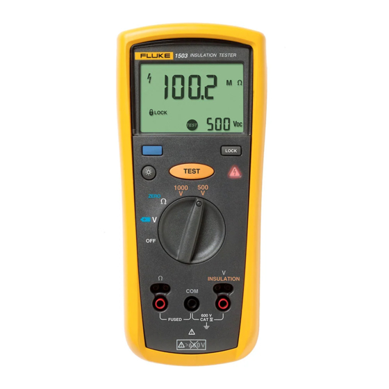
Introduction The Fluke Models 1503, 1507, and 1508 are battery-powered insulation testers (hereafter, Tester, Product, or DUT (Device Under Test)). These Testers meet CAT IV IEC 61010 standards. The IEC 61010 standard defines four measurement categories (CAT I to IV) based on the magnitude of danger from transient impulses. -
Page 6: Safety Information
150X Series Calibration Manual Safety Information XWWarning To prevent possible electrical shock or personal injury: Do not alter the Product and use only as specified, or the protection supplied by the Product can be compromised. Do not use the Tester or test leads if they appear damaged, or if the Tester is not ... -
Page 7: Contact Fluke
WARNING. Do not apply greater than 660 Volts. Contact Fluke Fluke Corporation operates worldwide. For local contact information, go to our website: www.fluke.com To register your product, view, print, or download the latest manual or manual supplement, go to our website www.fluke.com. - Page 8 h Static Awareness h Semiconductors and integrated circuits can be damaged by electrostatic discharge during handling. This notice explains how to minimize damage to these components. Understand the problem. Learn the guidelines for proper handling. Use the proper procedures, packaging, and bench techniques. Follow these practices to minimize damage to static sensitive parts.
-
Page 9: Test The Batteries
150X Series Calibration Manual Test the Batteries XWWarning To prevent possible electrical shock or personal injury, replace the battery when the low battery indicator (B) shows to prevent incorrect measurements. A weak battery can cause false readings. The Tester continuously monitors battery voltage. If the low battery icon (B) appears on the display, there is minimal battery life left. -
Page 10: Test The Display
F315 mA 1000 V Min interrupt rating 10000 A Fuse, Fast, 315 mA, 1000 V, Min Interrupt Rating 10000 A Fluke PN 2279339 Battery, 1.5 V AA Alkaline, NEDA 15A, IEC LR6 Fluke PN 376756 Test the Display Press and hold the blue key, and simultaneously turn the DUT on. Compare the display with the... -
Page 11: Keypad Test
150X Series Calibration Manual Keypad Test The keypad consists of six keys located above the rotary switch. To test the keypad: 1. Turn the rotary switch to and momentarily press each of the six keys. Each press of an operational key causes the Tester to beep. No beep in response to a key press indicates a defective keypad. -
Page 12: Remove The Holster
Insulation Testers Basic Maintenance Remove the Holster The standard Tester comes with a snug-fitting yellow rubber holster. The holster protects the Tester from rough handling and normally remains on the Tester. The first step to disassemble the Tester is to remove the holster. To remove the holster: 1. -
Page 13: Open The Bottom Case
150X Series Calibration Manual Open the Bottom Case With the battery door removed, the next step to disassemble the Tester is to remove the bottom case. To remove the bottom case: Note When you remove the back cover, you do not have to remove the fuse or the batteries. - Page 14 Insulation Testers Remove the PCA Figure 4. Insulation Terminal Clips 3. With one hand over the PCA, roll the top case over (face up) and lift it away from the PCA. Note Two red and one black plastic shields you attisolate the user from the input terminals. With the PCA removed, these shields are loose and can fall away from the PCA.
-
Page 15: Remove The Display
150X Series Calibration Manual Remove the Display With the PCA removed, the final step to disassemble the Tester is to remove the display assembly from the PCA. Refer to Figure 5 and use this procedure to remove the display assembly: 1. -
Page 16: Replacing The Lcd
Insulation Testers Remove the PCA Replace the LCD The display assembly consists of four pieces as shown in Figure Translucent light-dispersing back panel Flexible elastomeric conducting strip Plastic bezel for housing the components of the assembly Glass LCD ... -
Page 17: Required Tools And Equipment
150X Series Calibration Manual Required Tools and Equipment Table 2 Table 3 list the required equipment used in the Performance Test and Calibration Adjustments. If a recommended model is unavailable, use a substitute with equivalent or better specifications. Table 2. Required Performance Test Equipment... -
Page 18: Performance Tests
Tester (DUT) and its performance level. The performance test is recommended as an acceptance test for incoming inspection and as a calibration procedure to periodically ensure the accuracy of the Tester. Fluke recommends that you run the performance test at least once a year. -
Page 19: Discharge Circuit Test
To prevent damage to the calibrator, do not attempt to use the 5500A, 5520A, or other standard calibrator for the insulation tests. WCaution To prevent damage to the Fluke 5320A, make sure to select the High Ohms function before you push the T on the DUT. -
Page 20: Insulation Resistance Accuracy Tests
1. Connect the DUT terminals to the Fluke 5320A High Resistance INSULATION output terminals. 2. Set the Fluke 5320A to the high resistance source function (H). 3. Turn the DUT rotary function switch to an function. INSULATION 4. Select the DUT insulation voltage range per Table 5. -
Page 21: Insulation Function, External Sense
3. Set the Fluke 5320A for the applied load shown in Table 6 for Steps 1-5. 4. Press T and verify that the DUT and Fluke 5320A voltage reads within the limits of Table 6. Record both readings. 5. Use the Fluke 5320A voltage reading as the reference and calculate the DUT voltage reading error %, (5320A V - DUT V / 5320A V) x 100, and record for later use. -
Page 22: Source Voltage Accuracy Test, Open Circuit
Insulation Testers Performance Tests Source Voltage Accuracy Test, Open Circuit Determine the open circuit source voltage accuracy by calculation. use the DUT Voltage Reading Error % previously noted. Complete the subsequent test to verify the actual open circuit source voltage. 1. -
Page 23: I Nominal Test
3. Set the 5320A for the Applied Load called out in Table 8 for Steps 1-5. 4. Press T and make sure that the Fluke 5320A current reading is >1000.0 μA for steps 1-5. Table 8. I Nominal Test/Limit Test... -
Page 24: Test The Ohm Function
5. Press T and make sure that the DUT reads within the display reading limits shown in Table 6. Connect the Fluke 5320A high resistance output terminals to the DUT COM and Ω terminals. 7. Set the Fluke 5320A to the high resistance source function (H). -
Page 25: 2-Ohm Output Current Test
3. Set the DUT rotary function switch to the function. Ω 4. Press T and verify that the Fluke 5320A voltage reading is >4.0 V but <8.0 V. Calibration Adjustment The Tester features closed-case calibration adjustment and uses known reference sources. -
Page 26: Calibration Adjustment Password
Insulation Testers Calibration Adjustment Calibration Adjustment Password Enter the correct four-key password to start the calibration adjustment procedure. You can change the password or reset to the default as described in below. The default password is 1234. Change the Password To change the Tester password: 1. - Page 27 150X Series Calibration Manual Figure 6. Restore the Default Password Battery Pads Cal Keypad Keys Used in the Calibration Steps The Tester keys behave as follows when you do the calibration adjustment procedure: Tstores the calibration value and advances to the next step.
- Page 28 Insulation Testers Calibration Adjustment 7. Use Table 10 and apply the input value listed for each calibration adjustment step. For each step, position the rotary function switch and apply the input to the terminals as indicated in the table. 8. After you apply each input, press T to accept the value and proceed to the next step (C-02 and so forth).
- Page 29 150X Series Calibration Manual Table 10. Calibration Adjustment Steps Switch Position Input Terminal Adjustment Step Input Value C-01 0 mA, 0 Hz C-02 15 μA, 0 Hz 1000 V Insulation C-03 20 μA, 0 Hz C-04 1.8 mA, 0 Hz...
- Page 30 Table 13, and Table 14 identify the replacement parts unique to each model. Figure 7 shows the location of each part. To order replacement parts refer to Contact Fluke. Figure 7. 150X Replacement Parts MP32 MP18 H30-32 (3x) MP16 MP21...
- Page 31 MP16 FLUKE-15X7-8012,TILT STAND 2278143 MP18 FLUKE-15X7-8014,HOLSTER 2278162 MP19 FLUKE-15X7-8016,BATTERY CONTACT,NEG 2281317 MP20 FLUKE-15X7-8017,BATTERY CONTACT,POS 2281321 MP21 LCD,TN,3.0V,TRANSFLECTIVE,1/4-DUTY,1/3-BIAS 2156884 MP22-24 FLUKE 89-4-8012 ,BATTERY CONTACT, DUAL 666435 BATTERY,PRIMARY,MNO2- MP40-43 376756 ZN,1.5V,2.24AH,15A,LR6,ALKALINE,AA,14X50MM,BULK SCREW,5-14,.750,PAN,PHILLIPS,STEEL,BLK H26-29 832246 CHROMATE,THREAD FORMING SCREW,4-14,.312,PAN,PHILLIPS,STEEL,ZINC-CLEAR,THD H30-32 642931 FORM,#3 HEAD MP32...
- Page 32 1670641 MP48 ALLIGATOR CLIP,600/1000V,2MM JACK,BLACK 1670652 MP36 1508 USERS MANUAL (Chinese and English) 2416024 Table 13. 1507 Specific Parts Ref Des Description FLUKE-1507-8004-01,CASE TOP, PAD XFER 2282433 FLUKE-1507-8005-02,BRACKET,MASK,PAD XFER 2282491 FLUKE-1507-8018-01,KEYPAD 2388523 FLUKE-1507-8007-03,DOOR,ACCESS 2388561 MP46 TL224-4201,175-263-011 TEST LEADS RA2S 2070140 MP47 021-236-003,ALL.CLIP EX-LARGE RED IEC1010...
- Page 33 150X Series Calibration Manual...
Need help?
Do you have a question about the 150X Series and is the answer not in the manual?
Questions and answers