
Subscribe to Our Youtube Channel
Related Manuals for Fluke 1550C


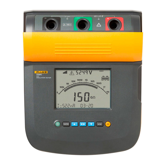
Summary of Contents for Fluke 1550C
- Page 1 1550C/1555 Insulation Tester Users Manual April 2010 Rev. 1, 3/18 ©2010-2018 Fluke Corporation. All rights reserved. All product names are trademarks of their respective companies. Specifications are subject to change without notice.
- Page 2 LIMITED WARRANTY AND LIMITATION OF LIABILITY Each Fluke product is warranted to be free from defects in material and workmanship under normal use and service. The warranty period is three years and begins on the date of shipment. Parts, product repairs, and services are warranted for 90 days. This warranty extends only to the original buyer or end-user customer of a Fluke authorized reseller, and does not apply to fuses, disposable batteries, or to any product which, in Fluke's opinion, has been misused, altered, neglected, contaminated, or damaged by accident or abnormal conditions of operation or handling.
-
Page 3: Table Of Contents
How to Contact Fluke ........ - Page 4 1550C/1555 Users Manual Insulation Test ............... 12 Store Test Results .
-
Page 5: Introduction
Introduction How to Contact Fluke The Fluke 1550C and 1555 Insulation Testers (the Tester or Product) To contact Fluke, use one of these telephone numbers: are high-voltage insulation testers to validate general circuits, such as • USA: 1-800-760-4523 switchgear, motors, and cables. -
Page 6: Safety Information
1550C/1555 Users Manual Safety Information • Do not use in CAT III or CAT IV environments without the protective cap installed on test probe. The identifies hazardous conditions and procedures that are protective cap decreases the exposed probe metal to Warning dangerous to the user. - Page 7 Insulation Tester Safety Information • • Remove all probes, test leads, and accessories that are Do not disconnect the test leads before a test has been not necessary for the measurement. completed and the test voltage at the terminals has returned to zero.
- Page 8 1550C/1555 Users Manual Table 1 is a list of symbols used on the Product or in this manual. Table 1. Symbols Symbol Description Symbol Description Conforms to relevant South Korean EMC standards. Consult user documentation. Conforms to relevant Australian EMC standards.
-
Page 9: Before You Start
Test Probes (red, black) Item Description Heavy Duty Alligator Clips: Red, Black, Green (1555 and kits only) Safety Shutter Available as optional accessory for 1550C, PN TLK1550-RTLC AC Plug Soft Carrying Case (Kit includes Hard Case) Input Terminals ... -
Page 10: Pushbuttons
1550C/1555 Users Manual Pushbuttons to access these menu items: 1.X Insulation Functions: Use the pushbuttons to control the Tester, view test results, and scroll through chosen test results. See Table 4. 1.1 Ramp off (default) Table 4. Pushbuttons 1.2 Ramp on... -
Page 11: Display
Insulation Tester The Tester Display Charge the Battery Table 5 is a list of features for the display. This Tester uses a rechargeable 12 V lead-acid battery for power. Table 5. Display Features Storing rechargeable lead-acid batteries in a low-charged state could decrease their life and cause damage. -
Page 12: Guard Terminal Use
1550C/1555 Users Manual Guard Terminal Use Figure 3 shows how to prevent surface current leakage with a lead connected from the Guard terminal to a conductor that surrounds the Note inner insulation. The surface leakage current is directed to the Guard Insulation resistance is measured between the (+) and (-) terminal. -
Page 13: Measurements
Insulation Tester Measurements Measurements Table 6. Test Lead Connections Common measurement procedures are discussed in this section. Connect to the Circuit Under Test XW Warning To prevent possible electric shock, fire or personal injury: • Remove all power from the circuit under test and discharge circuit capacitance before testing a circuit with the Product. -
Page 14: Before An Insulation Test
1550C/1555 Users Manual Before an Insulation Test Note The actual test voltage can be up to 10 % higher than the The Tester includes features and functions that let you adapt the test selected test voltage. to your requirements. These features let you: Program a Test Voltage •... -
Page 15: Select A Ramp Or Steady-State Test
Insulation Tester Measurements Select a Ramp or Steady-State Test Set a Timed Test The ramp-test function is an automated test that checks insulation for You can control the length of an insulation test by setting a timer. The a breakdown. During a ramp test, the output voltage starts at 0 V and time (test duration) can be set in 1-minute increments up to increases linearly (100 V/s) until it reaches the specified test voltage or 99 minutes. -
Page 16: Dielectric Absorption Ratio
Test Voltage – Set range: 250 V to 1000 V (50 V steps) – Set range: 1000 V to 10 000 V (100 V steps) Note 5000 V max for 1550C. • Ramp Test – Toggle on or off •... -
Page 17: Store Test Results
Insulation Tester Measurements XW Warning Any of these conditions terminate an insulation test: Before and after a test, confirm that the Product does • User stop (push not indicate the presence of a hazardous voltage. See • Timer limit reached Table 5. -
Page 18: View Test Results Stored In Memory
1550C/1555 Users Manual At each character position use or to assign a character (0-9, A-Z). Table 8. Stored Test Data Display Push to store the results. View Test Results Stored in Memory Note Parameters not appropriate for a test are shown as INVALID. -
Page 19: Download Test Results
The wireless radio does not cause interference with measurements. The app shows measurements on your smartphone or tablet display, saves to Fluke Cloud™ storage, and shares the information with your team. Note Changes or modifications to the wireless 2.4 GHz radio not... -
Page 20: Delete Test Results
• There are no user-replaceable parts inside the Product. Go to Settings > Bluetooth. Verify that Bluetooth is turned on. Go to the Fluke Connect app and in the list of connected Fluke Cleaning tools, select 155x FC. XW Warning Follow the prompts in the app to continue. -
Page 21: Replaceable Parts And Accessories
Insulation Tester Maintenance Replaceable Parts and Accessories Table 11. Accessories Table 10 is a list of the replaceable parts for the Product. Table 11 is a list of the available accessories. Accessory Part Number Table 10. Replaceable Parts Extended Test Lead Set, 25 feet (7.6 meters) 2032761 Part Part Number... -
Page 22: General Specifications
1550C/1555 Users Manual General Specifications Display..............475 mm x 105 mm Power..............12 V lead-acid rechargeable battery, 2.6 Ahr Typical Battery Charge Capacity Number of tests ............4100 @ 250 V 3600 @ 500 V 3200 @1 kV 2500 @ 2.5 kV... - Page 23 Insulation Tester Environmental Specifications afety ..............IEC 61010-1: 600 V CAT IV / 1000 V CAT III Pollution Degree 2 Electromagnetic Compatibility (EMC) International ............IEC 61326-1: Portable CISPR 11: Group 1, Class A Group 1: Equipment has intentionally generated and/or uses conductively-coupled radio frequency energy that is necessary for the internal function of the equipment itself.
-
Page 24: Electrical Specifications
1550C/1555 Users Manual Electrical Specifications The Tester accuracy is specified for 1 year after calibration at operating temperatures of 0 °C to 35 °C. For operating temperatures outside the range (-20 °C to 0 °C and 35 °C to 50 °C), add ±0.25 % per °C, except on the 20 % bands add ±1 % per °C. -
Page 25: Principles Of Measurement And Resistance
Insulation Tester Principles of Measurement and Resistance Measurement Range Accuracy ±(20 % + 2 nA) Leakage Current 1 nA to 2 mA 0.01 μF to 20.00 μF ±(15 % of reading + 0.03 μF) Capacitance Range Resolution Timer Setting: 1 minute 0 to 99 minutes Indication: 1 second Warning Range... - Page 26 1550C/1555 Users Manual...
Need help?
Do you have a question about the 1550C and is the answer not in the manual?
Questions and answers