Fluke 1550C, 1555 Manual
- User manual (50 pages) ,
- Calibration manual (32 pages) ,
- Technical data (2 pages)
Advertisement
- 1 Introduction
- 2 How to Contact Fluke
- 3 Safety Information
- 4 Symbols
- 5 Required Equipment
- 6 Performance Test Procedures
- 7 Adjustment Procedure
- 8 Additional Procedures
- 9 Static awareness
- 10 Battery Replacement Procedure
- 11 Cleaning
- 12 Replacement Parts/Accessories
- 13 Specifications
- 14 Principle of Measurement and Resistance
- 15 Documents / Resources
Introduction

To prevent possible electrical shock, fire, or personal injury:
- Do not perform the verification tests or calibration procedures described in this manual unless qualified to do so.
- Read all safety Information before you use or service the product.
The Calibration Manual for the 1550C/1555Insulation Tester (hereafter referred to as "the product") provides the following information.
- Fluke Contact Information
- Precautions and Safety Information
- Performance Test Procedures
- Adjustment Procedure
- Battery Replacement Procedure
- Replaceable Parts/Accessories
- Specifications
For complete operating instructions and additional safety information, refer to the 1550C/1555Users Manual located on the CD that came with the product.
How to Contact Fluke
To contact Fluke, call one of the following telephone numbers:
- Technical Support USA: 1-800-44-FLUKE (1-800-443-5853)
- Calibration/Repair USA: 1-888-99-FLUKE (1-888-993-5853)
- Canada: 1-800-36-FLUKE (1-800-363-5853)
- Europe: +31 402-675-200
- Japan: +81-3-3434-0181
- Singapore: +65-738-5655
- Anywhere in the world: +1-425-446-5500 Or, visit Fluke's website atwww.fluke.com.
To register your product, visit http://register.fluke.com.
To see, print, or download the latest manual supplement, visit http://us.fluke.com/usen/support/manuals.
Safety Information
A Warning identifies conditions and actions that pose hazard(s) to the user; A Caution identifies conditions and procedures that could cause Product damage, equipment under test damage, or permanent loss of data.
Read before product use.
To prevent possible electrical shock, fire, or personal injury:
- Read all safety Information before you use the product.
- Before and after testing, confirm that the product does not indicate the presence of a hazardous voltage, see Figure 2. If the product beeps continuously and a hazardous voltage is shown on the display, remove power from the circuit under test or allow the installation capacitance to fully discharge.
- Use the product only as specified, or the protection supplied by the product can be compromised.
- Connect the common test lead before the live test lead and remove the live test lead before the common test lead.
- Do not disconnect the test leads before a test has been completed and the test voltage at the terminals has returned to zero. This ensures that any charged capacitance is fully discharged.
- Disconnect power and discharge all high-voltage capacitors before you measure resistance or capacitance.
- Do not work alone.
- Do not use the product around vapor, or in damp or wet environments.
- Do not use test leads if they are damaged. Examine the test leads for damaged insulation, exposed metal, or if the wear indicator shows. Check test lead continuity.
- Do not use and disable the product if it is damaged.
- Do not touch voltages >30 V ac rms, 42 V ac peak, or 60 V dc.
- Keep fingers behind the finger guards on the probes.
- Do not exceed the Measurement Category (CAT) rating of the lowest rated individual component of a product, probe, or accessory.
- Accessories rated to 1000V CAT III/ 600V CAT IV are intended for hands-free use during insulation testing and are not to be touched while the output of the product exceeds the accessory's marked rating. Allow the product to fully discharge the installation before removing the test accessory.
- Impedances of additional operating circuits connected in parallel can adversely affect measurements.
- Use the correct terminals, function, and range for measurements.
- Do not operate the product with covers removed or the case open. Hazardous voltage exposure is possible.
- Use only specified replacement parts.
- Do not use the product if the safety shutter is impaired in any way. The safety shutter prevents access to the test terminals and charger terminals at the same time.
- There are no user replaceable parts inside the product.
- Use the guard terminal only as specified in this manual.
- Use only recommended test leads.
- Do not use in distribution systems with voltages higher than 1100 V.
Symbols
Symbols on the product and in the manual are explained Table 1.
Table 1. Symbols
| Symbol | Meaning |
 | Risk of Danger. Important information. See Manual. |
 | Hazardous voltage |
 | Equipment protected by double or reinforced insulation. |
  | Do not use in distribution systems with voltages higher than 1100 V. |
 | Interference is present. Displayed value might be outside of specified accuracy. |
 | Ramp mode indicator |
 | Electrical breakdown |
 | Volts AC |
 | Earth Ground |
Required Equipment
Equipment required to perform the procedures in this manual is listed in Table 2. If the recommended models are not available, equipment with equivalent specifications may be substituted.

For safe operation and maintenance of the product, have an approved technician repair the product.

Do not attempt to use the 5500A, 5520A, or other standard calibrator for insulation and continuity resistance tests. Calibrator damage will result.
Table 2. Required Equipment
| Equipment | Minimum Required Characteristics | Recommended Model |
| HV Probe | 6 kV, ±1% (1000:1 Divider) 11 kV, ±2% for the 1555 | Fluke 80K-6 80K-15 |
| Digital Multimeter | 500 mVdc to 1 V: ±0.02% | Fluke 8508 |
| 1Load with Guard Terminal | Resistances 200 kΩ, ±1.25%, 500 V 500 kΩ, ±1.25%, 500 V 1 MΩ, ±1.25%, 1 kV 2.5 MΩ, ±1.25%, 2.5 kV 5 MΩ, ±1.25%, 5 kV 10 MΩ, ±1.25%, 10 kV 1 GΩ, ±1.25%, 10 kV 100 GΩ, ±1.25%, 10 kV 200 GΩ, ±1.25%, 10 kV 500 GΩ, ±5%, 10 kV 1 TΩ, ±5%, 10 kV 2 TΩ, ±5%, 10 kV | Combinations of: Welwyn F Series, Welwyn MFP2 Series And Vishay HTS-523 |
| 2 Capacitors w/ Bleeder Resistors | 0.1 µF, ±5%, 500 V, Polypropylene 1 µF, ±5%, 2.5 kV, Polypropylene | |
| Calibrator | DC current: 2 mA Accuracy: ±1.25 % DC Voltage: 0 - 550 V Accuracy: ±0.005 % AC Voltage: 0 - 240 V, 60 Hz Accuracy: ±1.25% | Fluke 5080, Fluke 5520A |
| IR Cable Assembly | Fluke P/N 2166275 | |
| 3 Calibration Software | Snorre | |
| Ammeter | Fluke 8508 | |
| Personal computer | IBM compatible, with Microsoft Windows XP SP2 or later +.NetFramework 2.0 or later | |
| 1550C/1555Users Manual CD ROM | Fluke P/N 3592810 |
- Resistors must have a voltage coefficient consistent with the test voltage used.
- Can use (3) each, 0.033 µF, 2 kV capacitors in series and (8) each, 8 µF, 450 V capacitors in series to obtain required values. The 0.033 µF capacitors should have a 33 MΩ bleeder resistor across each capacitor. The 8 µF capacitors should have a 15 MΩ bleeder resistor across each capacitor.
- Available fromwww.fluke.com under 1550C/1555 Product Information.
Performance Test Procedures
To prevent possible electrical shock, fire, or personal injury, do not contact the output terminals while performing the following procedures. There are potentially dangerous voltages at the output terminals when the product is in the MΩ TEST function.
The following performance tests should be completed yearly to ensure that the product, referred to as "the UUT" (Unit Under Test) in this section of the manual, is in proper operating condition and meets the published accuracy specifications. If the UUT fails any of the performance test steps, repair or adjustment is needed. Refer to How to Contact Fluke for service information.
IR Port Verification Test
To verify operation of the IR Communications Port:
- Using a Windows PC, connect the IR adapter cable from the product IR port to the computer COM port.
- Activate the Snorre program from the Windows Start menu.
- SelectDiagnostic.
- SelectIdentification(ID). The PC sends out an ID command and the product responds to it.
Button Test
Use the pushbuttons to control the product, view test results, and scroll through chosen test results. Pushbuttons and their functionality are discussed in Figure 1.

Figure 1. Pushbuttons
| Item | Description |
| 1 | Turns the product off and on. |
| 2 | Push  to go to the Function menu. Push again to exit the Function menu. To scroll within the Function menu, use the arrow pushbuttons. to go to the Function menu. Push again to exit the Function menu. To scroll within the Function menu, use the arrow pushbuttons. |
| 3 | Scrolls through test voltages, stored test results, timer duration, and changes test tag ID characters. Also used to answer "yes" to yes/no prompts. |
| 4 | After a memory location is set,  displays the test parameters, test results stored in memory. These include voltage, capacitance, polarization index, dielectric absorption ratio, and current. displays the test parameters, test results stored in memory. These include voltage, capacitance, polarization index, dielectric absorption ratio, and current. |
| 5 | Use to scroll through test voltages, stored test results, timer duration, and memory locations. Also used to answer "no" to yes/no prompts. |
| 6 | Use for Test Voltage mode to start incrementally setting the test voltage between 250 V and 10,000 V. |
| 7 | Starts and stops a test. Push and hold for 1 second to start a test. Push again to stop a test. |
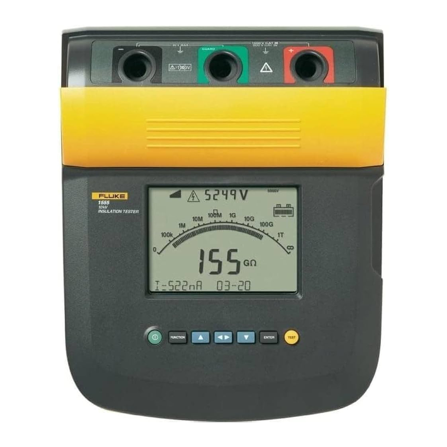
Display Test
Turn the UUT on several times while observing the display during power up. Compare the display with the example in Figure 2. Check all segments for clarity and contrast.

Figure 2. Display Features
| Item | Description |
| 1 | Interference present. Readings could be out of specified accuracy range. |
| 2 | Polarization Index |
| 3 | Dielectric Absorption Ratio |
| 4 | Electrical breakdown in Ramp mode |
| 5 | Ramp mode indicator |
| 6 | Possible hazardous voltage is at the test terminals. To prevent personal injury, before and after testing, confirm that the product does not indicate the presence of hazardous voltage. If the product beeps continuously and there is hazardous voltage, disconnect test leads and remove power from the circuit under test. |
| 7 | Voltage sourced by the product or from the circuit under test at terminals of the product. |
| 8 | Test voltage selection (250 V, 500 V, 1000 V, 2500 V, 5000 V, or 10,000 V) |
| 9 | Battery charge status |
| 10 | Bar graph display of insulation resistance |
| 11 | Digital display of insulation resistance |
| 12 | Text display. Shows voltage, test current, capacitance, programmable test voltages, and menu options. |
Charging Test
- With the product switched off, connect a mains supply to the ac supply receptacle and check that the UUT display showsCharging.
- Disconnect the mains supply and check that the UUT turns off.
- Turn the product on and see that all the battery symbol segments display as shown in Figure 2.
Note
A fully-charged battery is indicated when the battery symbol shows all segments. Recharge the battery as necessary to obtain all segments. A full charge may require 12 hours.
Insulation Accuracy Test
Using the various resistances shown in Table 3, perform the UUT insulation accuracy test. Push  for 2 seconds to start or discontinue a test.
Notes
- For best results, allow for settling of up to 60 seconds when measuring high-value resistances (100 GΩand above) and take care to avoid stray currents. Perform the test on a conductive work surface that is connected to the UUT's GUARD terminal and the load GUARD terminal.
- Motion/body capacitance can affect the stability of the reading at higher resistances. When taking the measurements above 1 GΩ, remain as motionless as possible.
The capacitance reading is obtained by pressing  after a test has started.
Table 3. Insulation Accuracy Test
| Step | Voltage Range | Resistance | UUT Display Limits | |
| Minimum | Maximum | |||
| 1 | 250 V | 0.1 µF | 0.055 | 0.145 |
| 2 | 500 V | 250 kΩ | 237 kΩ | 263 kΩ |
| 3 | 500 V | 1 GΩ | 0.95 GΩ | 1.05 GΩ |
| 4 | 500 V | 100 GΩ | 80 GΩ | 120 GΩ |
| 5 | 1 kV | 1 GΩ | 0.95 GΩ | 1.05 GΩ |
| *6 | 2.1 kV | 1 µF | 0.82 | 1.18 |
| 7 | 2.5 kV | 1 GΩ | 0.95 GΩ | 1.05 GΩ |
| 8 | 5 kV | 1 GΩ | 0.95 GΩ | 1.05 GΩ |
| 9 | 5 kV | 100 GΩ | 95 GΩ | 105 GΩ |
| 10 | 5 kV | 1 TΩ | 0.80 TΩ | 1.20 TΩ |
| 11 | 5 kV | 5 MΩ | 4.75 MΩ | 5.25 MΩ |
| **12 | 10 kV | 1 GΩ | 0.95 GΩ | 1.05 GΩ |
| **13 | 10 KV | 200 GΩ | 190 GΩ | 210 GΩ |
| **14 | 10 KV | 2 TΩ | 1.6 TΩ | 2.4 TΩ |
| **15 | 10 KV | 10 MΩ | 9.5 MΩ | 10.5 MΩ |
| ** 1555 only * Use "Programmable Test Voltage" mode by pushing  . . | ||||
Output Voltage Test
In Table 4, the UUT output voltage is checked with various loads applied. In this test a voltmeter with a high-voltage probe must be connected to the load resistor to measure the UUT output voltage. Use 15 80K-6 for voltages below 6 kV.
Table 4. Output Voltage Test
| Step | Voltage Range | Load Resistor | Reading Limits | |
| Minimum | Maximum | |||
| 1 | 250 V | 250 kΩ | 250 V | 275 V |
| 2 | 250 V | No Load | 250 V | 275 V |
| 3 | 500 V | 500 kΩ | 500 V | 550 V |
| 4 | 500 V | No Load | 500 V | 550 V |
| 5 | 1 kV | 1 MΩ | 1000 V | 1100 V |
| 6 | 1 kV | No Load | 1000 V | 1100 V |
| 7 | 2.5 kV | 2.5 MΩ | 2500 V | 2750 V |
| 8 | 2.5 kV | No Load | 2500 V | 2750 V |
| 9 | 5 kV | 5 MΩ | 5000 V | 5500 V |
| 10 | 5 kV | No Load | 5000 V | 5500 V |
| *11 | 10 kV | No Load | 10000 V | 11000 V |
| *12 | 10 kV | 10 MΩ | 10000 V | 11000 V |
| * 1555 only. Requires 80K-15 probe. | ||||
Short Circuit Current Test
To verify the UUT short circuit current, use the following procedure:
- Connect an ammeter between the UUT + and - terminals.
- Turn the UUT on and allow to startup.
- Wait forTest Voltage to appear on the display and set the test voltage to 5000 V by pushing
![]() .
. - Push
![]() and note that the ammeter reading is within the reading limits referred to in Table 5.
and note that the ammeter reading is within the reading limits referred to in Table 5. - Push
![]() to discontinue the test.
to discontinue the test.
 .
. and note that the ammeter reading is within the reading limits referred to in Table 5.
 to discontinue the test.
Table 5. Short Circuit Current Test
| UUT | Voltage Range | Reading Limits | |
| Minimum | Maximum | ||
| 1550C | 5000 V | 1.20 mA | 1.80 mA |
| 1555 | 10000 V | 1.20 mA | 1.80 mA |
Voltage Measurement Accuracy
To verify voltage measurement accuracy of the Live Circuit Warning function, apply the voltages listed in Table 6 to the + and - terminals of the UUT. Verify that:
- The UUT reading is within the display limits of Table 6.
- The UUT is beeping at a 1-second interval.
![shock hazard]() is flashing on the display.
is flashing on the display.
Table 6. Voltage Measurement Test
| Step | Voltage Source Output | UUT Display | UUT Tone | UUT Display Limits | |
| Minimum | Maximum | ||||
| 1 | -34 Vdc | Flashing Hazard | Beeps | 29 V | 39 V |
| 2 | 240 Vac, 60 Hz | Flashing Hazard | Beeps | 204 V | 276 V |
Adjustment Procedure
The product should be performance tested yearly to ensure compliance with its specifications. When required, use the following adjustment procedure to bring the UUT within its nominal accuracy specifications.
Interface Connection
Perform adjustment with software using a computer and IR (infrared) adapter.
Connect the Infrared Cable Assembly to the UUT IR Port and COM port of the computer. Refer to Figure 3.

Figure 3. IR Port
| Item | Description |
| 1 | IR Port |
| 2 | IR Device |
Instrument Setup
Turn the product on and wait for Test Voltage to appear on the display. From the computer terminal, activate the Snorre program from the Windows Start menu. On the Setup tab, confirm the selected COM port settings.
To prevent possible electrical shock, fire, or personal injury, do not contact the output terminals or test equipment terminals while performing the following procedures. There are potentially dangerous voltages when the UUT is in the "Calibrate HV Output and Measurement" mode.
Normalizing the HV Probe and Digital Multimeter
- Connect the HV probe and digital multimeter to the 5520ANORMAL output terminals, observing polarity. Manually set the multimeter for a range that has a 10 MΩ input impedance (e.g., 100 V) and provides a maximum resolution for a 500 mV and 5000 mV input.
- Set the 5520A output to 506 V and note the digital multimeter reading. Record this value.
- Set the 5520A output to 1000 V and note the voltmeter reading. If the error is > 0.025% from the nominal value, convert the error from nominal to percentage. Multiply 5005 V by this percentage and algebraically add to 5005 V. Record this value.
- Set the 5520A to standby and disconnect the HV probe and digital multimeter.
HV Adjustment
- Select theCAL HV tab.
- Connect the HV probe and digital multimeter to the output terminals of the UUT, as shown in the connection diagram.
- Press theSTART button to begin adjustment. The UUT briefly displays HV OFFSET then flashes
![shock hazard]() with PWM 600, while emitting a beep at 1-second intervals.
with PWM 600, while emitting a beep at 1-second intervals. - Use
![]() and
and ![]() on the terminal to modify the UUT output value to as close as possible to the value recorded in step 2 of "Normalizing the HV Probe and Digital Multimeter". The nominal value for this adjustment is between 502 and 510 V.
on the terminal to modify the UUT output value to as close as possible to the value recorded in step 2 of "Normalizing the HV Probe and Digital Multimeter". The nominal value for this adjustment is between 502 and 510 V. - Press theCal 500 button. The UUT now increases its output of the 1550C to nominally 5000 V, the output of the 1555 goes to a nominal 10,000 V.
- Use
![]() and
and ![]() on the terminal to modify the UUT output value to as close as possible to the value obtained in step 3 of "Normalizing the HV Probe and Digital Multimeter". The nominal value for the 1550C adjustment is between 5000 V and 5010 V, the target range for the 1555 adjustment is 10,000 V and 10,020 V.
on the terminal to modify the UUT output value to as close as possible to the value obtained in step 3 of "Normalizing the HV Probe and Digital Multimeter". The nominal value for the 1550C adjustment is between 5000 V and 5010 V, the target range for the 1555 adjustment is 10,000 V and 10,020 V. - Press theCal 500 button. The HV generation and measurement functions are now calibrated.
- Disconnect the HV probe and digital multimeter from the UUT.
 and
and  on the terminal to modify the UUT output value to as close as possible to the value recorded in step 2 of "Normalizing the HV Probe and Digital Multimeter". The nominal value for this adjustment is between 502 and 510 V.
Current Adjustment
- Select theCal Current tab.
- Attach a 2 mA current source to the LO and GUARD terminals of the UUT, connecting the current source LO to UUT GUARD terminal, as shown in the connection diagram.
- Apply 2 mAdc to the UUT.
- Press theSTART button and wait until the adjustment is complete.
- The current measurement is now adjusted. Disconnect the current source.
Charge Adjustment
- Select theCal Charge tab.
- Attach a 2 mA current source to the LO and GUARD terminals of the UUT, connecting the current source LO to UUT Guard.
- Apply 2 mAdc to the UUT.
- Press theStart button and wait until the adjustment is complete; progress is displayed.
- The charge measurement is now adjusted. Set the current source toSTANDBY and disconnect it from the UUT.
This completes the Adjustment Procedure.
Additional Procedures
Note
The following additional procedures are used during factory calibration and repair but should not be performed in the field. They are included for information only.
Various diagnostics are available from the Diagnostic tab as follows:
Identification (Id)
This button installs the default opvars in the UUT; the present calibration is lost as the opvars are overwritten with the defaults. The user is presented with a YES/NO dialog box, to prevent accidental selection of this option.
Restart UUT
This button first sets the UUT to CAL_DIAGS mode the sends out the restart hardware command. The UUT is then restarted.
Shutdown UUT
This button puts the UUT into CAL_DIAGS mode and sends out the powerdown command.
Get Diagnostics
Pressing this button continually gets Raw ADC values from the UUT and updates the Raw ADC Counts boxes (v_counts, i_counts, q_counts), pressing the button again turns this feature off.
Query Constants
Pressing this button provides an html screen dump of the present opvars obtained from the UUT. You will need to check that numerical values are reported for all nine variables. See Figure 4.

Figure 4. Query Constant Result
Save / Print html Page
The Save button brings up a Windows Save Dialog Box so that the html document being displayed can be saved to file.
The Print button brings up a Windows Print Dialog Box so that the rendered html document may be printed.
The window at the bottom of the page is a scrollable log of the Snorre methods issuing commands to the UUT and the corresponding responses received back from the UUT.
Static awareness

A Message From Fluke Corporation

Some semiconductors and custom IC's can be damaged by electrostatic discharge during handling. This notice explains how you can minimize the chances of destroying such devices by:
- Knowing that there is a problem.
- Learning the guidelines for handling them.
- Using the procedures, packaging, and bench techniques that are recommended.
The following practices should be followed to minimize damage to S.S. (static sensitive) devices.
- MINIMIZE HANDLING
![]()
- KEEP PARTS IN ORIGINAL CONTAINERS UNTIL READY FOR USE.
![]()
- DISCHARGE PERSONAL STATIC BEFORE HANDLING DEVICES. USE A HIGH RESIS TANCE GROUNDING WRIST STRAP.
![]()
- HANDLE S.S. DEVICES BY THE BODY.
![]()
- USE STATIC SHIELDING CONTAINERS FOR HANDLING AND TRANSPORT.
![]()
- DO NOT SLIDE S.S. DEVICES OVER ANY SURFACE.
![]()
- AVOID PLASTIC,VINYL AND STYROFOAM IN WORK AREA.
![]()
- WHEN REMOVING PLUG-IN ASSEMBLIES HANDLE ONLY BY NON-CONDUCTIVE EDGES AND NEVER TOUCH OPEN EDGE CONNECTOR EXCEPT AT STATIC-FREE WORK STATION. PLACING SHORTING STRIPS ON EDGE CONNECTOR HELPS PROTECT INSTALLED S.S. DEVICES.
![]()
- HANDLE S.S. DEVICES ONLY AT A STATIC-FREE WORK STATION.
![]()
- ONLY ANTI-STATIC TYPE SOLDER SUCKERS SHOULD BE USED.
- ONLY GROUNDED-TIP SOLDERING IRONS SHOULD BE USED.


Battery Replacement Procedure
For safe operation and maintenance of the product:
- Batteries contain hazardous chemicals that can cause burns or explode. If exposure to chemicals occurs, clean with water and get medical aid.
- Remove all probes, test leads, and accessories before the battery door is opened.
- Remove all probes, test leads, and accessories before the case is opened.
- The battery door must be closed and locked before you operate the product.
- Use only specified replacement fuses and batteries.
- Do not disassemble the battery.
To prevent possible damage to the product or to equipment under test:
- Do not attempt to repair or service the product unless qualified to do so and you have the relevant calibration, performance test, and service information.
- Remove batteries to prevent battery leakage and damage to the product if it is not used for an extended period.
- Be sure that the battery polarity is correct to prevent battery leakage.
- Repair the product before use if the battery leaks.
- Do not disassemble the battery.
- Do not short the battery terminals together.
- Keep cells and battery packs clean and dry. Clean dirty connectors with a dry, clean cloth.
- Do not disassemble or crush battery cells and battery packs.
- Do not keep cells or batteries in a container where the terminals can be shorted.
- Do not put battery cells and battery packs near heat or fire.
Do not put in sunlight.
Note
This instrument contains a lead-acid battery. Do not mix with the solid waste stream. Spent batteries should be disposed of by a qualified recycler or hazardous materials handler. Contact your authorized Fluke Service Center for disposal and recycling information.
Storing rechargeable lead-acid batteries in a low-charged state could lead to reduced life and/or damage. Fully charge the battery before storing for extended periods and check, the charge at regular intervals.
The product is powered by 12 V lead acid battery, Fluke P/N 2803592. The battery can be recharged using the AC power cord.
Fully charging the battery typically takes 12 hours. Avoid charging in extremes of temperature. Recharge the battery if the product has been stored for extended periods.
If the battery needs to be replaced, use the following procedure to replace the battery.
Disassembly
To prevent possible damage to the product or to equipment under test, disassembly must be performed using proper ESD handling techniques. Place the product on an anti-static mat and use a grounded wrist strap during the following procedure.
- Disconnect the test leads from any live source and power off the product.
- Remove the mains supply cable leads from the instrument.
- Turn the product over and place it on a level surface with feet up.
- Remove the 4 screws from the case. This frees the top assembly from the base. The battery is attached to the base.
- Lift the base from the top assembly and set it on its side next to the top assembly.
- Disconnect the red and black leads for the battery.
- Set the base on its feet and remove the 4 screws from the battery bracket.
- Remove the bracket.
- The battery (PN 2803592) can now be removed.
Re-assembly
- Place the new battery assembly in position and then reinstall the battery bracket.
- Reverse steps 2 through 9 of the disassembly procedure to re-assemble. When reconnecting the red and black battery leads, the red wire must be connected to the + terminal of the battery. Connect the black wire to the – terminal.
Cleaning
For safe operation and maintenance of the product, remove excess water from the cloth before cleaning the product to ensure that water does not enter any terminal.
Periodically wipe the case with a damp cloth and mild detergent. Do not use abrasives or solvents to clean the product.
Replacement Parts/Accessories
Replacement parts are listed in Table 7.
Table 7. Replacement Parts
| Parts | Part Number |
| Test Lead Set Fluke 1550 | 3477137 |
| 10 kV Clip | 3611951 |
| 1550C 1555 Safety Input Cover | 3529198 |
| 1550C Top Case | 3622602 |
| 1555 Top Case | 3624655 |
| Input Jacks Decal | 3624643 |
| Case Screws | 3552926 |
| IR Cable Assembly | 2166275 |
| Battery Hold Bracket | 3540654 |
| Case Bottom | 3524293 |
| Battery | 2803592 |
| Rubber Foot | 3777953 |
| AC Power Cord (S. Africa) | 1552363 |
| AC Power Cord (Australia) | 658641 |
| AC Power Cord (UK) | 769455 |
| AC Power Cord (Continental Europe) | 789422 |
| AC Power Cord (North America) | 284174 |
| Soft Carrying Case | 3592805 |
| Extended Lead Set (5 kV rating) | 2032761 |
| 1550C/1555 Quick Reference Card | 3592822 |
| 1550C/1555 CD ROM (includes Users Manuals [English, French, German, Spanish]) | 3592810 |
Specifications
General Specifications
| Display | 75 mm x 105 mm | |
| Power | 12 V lead-acid rechargeable battery. 2.6 Ahr | |
| Charger Input (AC) | 85 V to 250 V ac, 50/60 Hz, 20 VA This Class II (double insulated) instrument is supplied with a Class 1 (grounded) power cord. The protective earth terminal (ground pin) is not connected internally. The extra pin is for added plug retention only. | |
| Dimensions (H x W x L) | 170 mm x 242 mm x 330 mm (6.7 in. x 9.5 in. x 13.0 in.) | |
| Weight | 3.6 kg (7.94 lbs.) | |
| Temperature (operating) | -20 °C to 50 °C (-4 °F to 122 °F) | |
| Temperature (storage) | -20 °C to 65 °C (-4 °F to 149 °F) | |
| Relative Humidity | 80% to 31 °C decreasing linearly to 50% at 50 °C | |
| Altitude | 2000 m | |
| Enclosure Sealing | IP40 | |
| Input Overload Protection | 1000 V ac | |
| Electromagnetic Compatibility | EN 61326-1, EN 61326-2-2 | |
| Safety Compliance | EN 61010-1, EN 61557 Parts 1 and 2 CAT III 1000V, CAT IV 600V | |
| Pollution Degree | 2 | |
| Typical Battery Charge Capability Note: At temperature extremes, the battery needs to be charged more frequently. | Test Voltages | Number of Tests |
| 250 V | 4100 | |
| 500 V | 3600 | |
| 1 kV | 3200 | |
| 2.5 kV | 2500 | |
| 5 kV | 1000 | |
| 10 kV | 500 | |
Electrical Specifications
Product accuracy is specified for 1 year after calibration at operating temperatures of 0°C to 35°C. For operating temperatures outside the range (-20°C to 0°C and 35°C to 50°C), add ±0.25% per °C, except on the 20% bands add ±1% per °C.
| Insulation | |||
| Test Voltage (DC) | Insulation Resistance Range | Accuracy (±reading) | |
| 250 V | <200 kΩ 200 kΩ to 5 GΩ 5 GΩ to 50 GΩ >50 GΩ | unspecified 5 % 20% unspecified | |
| 500 V | <200 kΩ 200 kΩ to 10 GΩ 10 GΩ to 100 GΩ >100 GΩ | unspecified 5 % 20% unspecified | |
| 1000 V | <200 kΩ 200 kΩ to 20 GΩ 20 GΩ to 200 GΩ >200 GΩ | unspecified 5 % 20% unspecified | |
| 2500 V | <200 kΩ 200 kΩ to 50 GΩ 50 GΩ to 500 GΩ >500 GΩ | unspecified 5 % 20% unspecified | |
| 5000 V | <200 kΩ 200 kΩ to 100 GΩ 100 GΩ to 1 TΩ >1 TΩ | unspecified 5 % 20% unspecified | |
| 10,000 V | <200 kΩ 200 kΩ to 200 GΩ 200 GΩ to 2 TΩ >2 TΩ | unspecified 5 % 20% unspecified | |
| Bar graph range: Insulation test voltage accuracy: Induced ac mains current rejection: Charging rate for capacitive load: | 0 to 2 TΩ -0%, +10% at 1 mA load current 2 mA maximum 5 seconds per µF | ||
| Discharge rate for capacitive load: | 1.5 s/µF | ||
| Leakage Current Measurement | Range | Accuracy |
| 1 nA to 2 mA | ±(20% + 2 nA) | |
| Capacitive Measurement | 0.01 µF to 20.00 µF | ±(15% of reading + 0.03 µF) |
| Timer | Range | Resolution |
| 0 to 99 minutes | Setting: 1 minute Indication: 1 second | |
| Live circuit warning | Warning Range | Voltage Accuracy |
| 30 V to 1100 V ac/dc, 50/60 Hz | ±(15% + 2 V) |
Short circuit current
> 1 mA and < 2 mA
Principle of Measurement and Resistance
The product measures insulation parameters and displays the results using with the following formulas.
| Ohm's Law | Capacitance (charge) | PI (Polarization Index) | DAR (Dielectric absorption ratio) |
 |  |  |  |
Documents / Resources
References
![www.fluke.com]() Fluke Corporation: Fluke Electronics, Calibration and Networks
Fluke Corporation: Fluke Electronics, Calibration and NetworksFluke Registration
![us.fluke.com]() Search results | Fluke
Search results | Fluke
Download manual
Here you can download full pdf version of manual, it may contain additional safety instructions, warranty information, FCC rules, etc.
Advertisement


Need help?
Do you have a question about the 1550C and is the answer not in the manual?
Questions and answers