Table of Contents
Advertisement
®
Advanced Test Equipment Rentals
www.atecorp.com 800-404-ATEC (2832)
1550C/1555
Insulation Tester
Calibration Manual
September 2010
© 2010 Fluke Corporation. All rights reserved. Printed in USA. Specifications are subject to change without notice.
All product names are trademarks of their respective companies.
Advertisement
Table of Contents

Related Manuals for Fluke 1550C


Summary of Contents for Fluke 1550C
- Page 1 Advanced Test Equipment Rentals www.atecorp.com 800-404-ATEC (2832) 1550C/1555 Insulation Tester Calibration Manual September 2010 © 2010 Fluke Corporation. All rights reserved. Printed in USA. Specifications are subject to change without notice. All product names are trademarks of their respective companies.
- Page 2 Fluke authorized resellers shall extend this warranty on new and unused products to end-user customers only but have no authority to extend a greater or different warranty on behalf of Fluke. Warranty support is available only if product is purchased through a Fluke authorized sales outlet or Buyer has paid the applicable international price. Fluke reserves the right to invoice Buyer for importation costs of repair/replacement parts when product purchased in one country is submitted for repair in another country.
-
Page 3: Table Of Contents
Table of Contents Title Page Introduction......................1 How to Contact Fluke ..................2 Safety Information ..................... 2 Symbols ......................4 Required Equipment ..................5 Performance Test Procedures ................6 IR Port Verification Test ................6 Button Test ....................7 Display Test....................8 Charging Test .................... - Page 4 1550C/1555 Calibration Manual...
- Page 5 List of Tables Table Title Page Symbols........................4 Required Equipment....................5 Insulation Accuracy Test..................10 Output Voltage Test ....................11 Short Circuit Current Test ..................11 Voltage Measurement Test..................12 Replacement Parts ....................18...
- Page 6 1550C/1555 Calibration Manual...
- Page 7 List of Figures Figure Title Page Pushbuttons ......................7 Display Features..................... 8 IR Port ........................12 Query Constant Result ................... 15...
- Page 8 1550C/1555 Calibration Manual...
-
Page 9: Introduction
• Read all safety Information before you use or service the product. The Calibration Manual for the 1550C/1555Insulation Tester (hereafter referred to as "the product") provides the following information. • Fluke Contact Information •... -
Page 10: How To Contact Fluke
1550C/1555 Calibration Manual How to Contact Fluke To contact Fluke, call one of the following telephone numbers: • Technical Support USA: 1-800-44-FLUKE (1-800-443-5853) • Calibration/Repair USA: 1-888-99-FLUKE (1-888-993-5853) • Canada: 1-800-36-FLUKE (1-800-363-5853) • Europe: +31 402-675-200 • Japan: +81-3-3434-0181 •... - Page 11 Insulation Tester Safety Information • Do not use test leads if they are damaged. Examine the test leads for damaged insulation, exposed metal, or if the wear indicator shows. Check test lead continuity. • Do not use and disable the product if it is damaged. •...
-
Page 12: Symbols
Interference is present. Displayed value might be outside of specified accuracy. Ramp mode indicator Electrical breakdown Volts AC Earth Ground Do not dispose of this product as unsorted municipal waste. Go to Fluke’s website for recycling information. -
Page 13: Required Equipment
DC current: 2 mA Fluke 5080, Accuracy: ±1.25 % Fluke 5520A DC Voltage: 0 - 550 V Accuracy: ±0.005 % AC Voltage: 0 - 240 V, 60 Hz Accuracy: ±1.25 % IR Cable Assembly Fluke P/N 2166275 Calibration Software Snorre Ammeter Fluke 8508... -
Page 14: Performance Test Procedures
The 0.033 μF capacitors should have a 33 MΩ bleeder resistor across each capacitor. The 8 μF capacitors should have a 15 MΩ bleeder resistor across each capacitor. 3. Available from www.fluke.com under 1550C/1555 Product Information. Performance Test Procedures Warning To prevent possible electrical shock, fire, or personal injury, do not contact the output terminals while performing the following procedures. -
Page 15: Button Test
Insulation Tester Performance Test Procedures Button Test Use the pushbuttons to control the product, view test results, and scroll through chosen test results. Pushbuttons and their functionality are discussed in Figure 1. FUNCTION ENTER TEST ghh02.eps Item Description Turns the product off and on. ... -
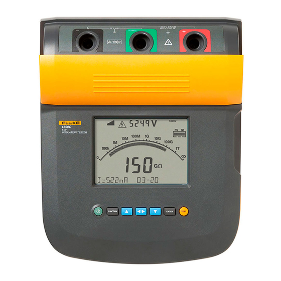
Page 16: Display Test
1550C/1555 Calibration Manual Display Test Turn the UUT on several times while observing the display during power up. Compare the display with the example in Figure 2. Check all segments for clarity and contrast. gHH03f.EPS Item Description Interference present. Readings could be out of specified accuracy range. -
Page 17: Charging Test
Insulation Tester Performance Test Procedures Charging Test 1. With the product switched off, connect a mains supply to the ac supply receptacle and check that the UUT display shows Charging. 2. Disconnect the mains supply and check that the UUT turns off. 3. - Page 18 1550C/1555 Calibration Manual The capacitance reading is obtained by pressing after a test has started. Table 3. Insulation Accuracy Test UUT Display Limits Step Voltage Range Resistance Minimum Maximum 0.1 μF 250 V 0.055 0.145 500 V 250 kΩ...
-
Page 19: Output Voltage Test
Table 5. 5. Push to discontinue the test. Table 5. Short Circuit Current Test Reading Limits Voltage Range Minimum Maximum 1550C 5000 V 1.20 mA 1.80 mA 1555 10000 V 1.20 mA 1.80 mA... -
Page 20: Voltage Measurement Accuracy
1550C/1555 Calibration Manual Voltage Measurement Accuracy To verify voltage measurement accuracy of the Live Circuit Warning function, apply the voltages listed in Table 6 to the + and - terminals of the UUT. Verify that: • The UUT reading is within the display limits of Table 6. -
Page 21: Instrument Setup
Multimeter”. The nominal value for this adjustment is between 502 and 510 V. 5. Press the Cal 500 button. The UUT now increases its output of the 1550C to nominally 5000 V, the output of the 1555 goes to a nominal 10,000 V. -
Page 22: Current Adjustment
1550C/1555 Calibration Manual Current Adjustment 1. Select the Cal Current tab. 2. Attach a 2 mA current source to the LO and GUARD terminals of the UUT, connecting the current source LO to UUT GUARD terminal, as shown in the connection diagram. -
Page 23: Get Diagnostics
Insulation Tester Additional Procedures Get Diagnostics Pressing this button continually gets Raw ADC values from the UUT and updates the Raw ADC Counts boxes (v_counts, i_counts, q_counts), pressing the button again turns this feature off. Query Constants Pressing this button provides an html screen dump of the present opvars obtained from the UUT. - Page 24 A Message From Fluke Corporation Some semiconductors and custom IC's can be damaged by electrostatic discharge during handling. This notice explains how you can minimize the chances of destroying such devices 1. Knowing that there is a problem.
- Page 25 8. WHEN REMOVING PLUG-IN ASSEMBLIES 5. USE STATIC SHIELDING CONTAINERS FOR HANDLE ONLY BY NON-CONDUCTIVE HANDLING AND TRANSPORT. EDGES AND NEVER TOUCH OPEN EDGE CONNECTOR EXCEPT AT STATIC-FREE WORK STATION. PLACING SHORTING STRIPS ON EDGE CONNECTOR HELPS PROTECT INSTALLED S.S. DEVICES. 6.
-
Page 26: Battery Replacement Procedure
1550C/1555 Calibration Manual Battery Replacement Procedure Warning For safe operation and maintenance of the product: • Batteries contain hazardous chemicals that can cause burns or explode. If exposure to chemicals occurs, clean with water and get medical aid. • Remove all probes, test leads, and accessories before the battery door is opened. -
Page 27: Disassembly
Fully charge the battery before storing for extended periods and check, the charge at regular intervals. The product is powered by 12 V lead acid battery, Fluke P/N 2803592. The battery can be recharged using the AC power cord. -
Page 28: Cleaning
769455 AC Power Cord (Continental Europe) 789422 AC Power Cord (North America) 284174 Soft Carrying Case 3592805 Extended Lead Set (5 kV rating) 2032761 1550C/1555 Quick Reference Card 3592822 1550C/1555 CD ROM (includes Users Manuals [English, French, German, 3592810 Spanish]) -
Page 29: Specifications
Insulation Tester Specifications Specifications General Specifications Display 75 mm x 105 mm 12 V lead-acid rechargeable battery. Power 2.6 Ahr 85 V to 250 V ac, 50/60 Hz, 20 VA This Class II (double insulated) instrument is supplied with a Class 1 Charger Input (AC) (grounded) power cord. -
Page 30: Electrical Specifications
1550C/1555 Calibration Manual Electrical Specifications Product accuracy is specified for 1 year after calibration at operating temperatures of 0 °C to 35 °C. For operating temperatures outside the range (-20 °C to 0 °C and 35 °C to 50 °C), add ±0.25 % per °C, except on the 20 % bands add ±1 % per °C. -
Page 31: Principle Of Measurement And Resistance
Insulation Tester Principle of Measurement and Resistance Range Accuracy Leakage Current Measurement ±(20 % + 2 nA) 1 nA to 2 mA Capacitive 0.01 μF to 20.00 μF ±(15 % of reading + 0.03 μF) Measurement Range Resolution Timer Setting: 1 minute 0 to 99 minutes Indication: 1 second Warning Range... - Page 32 1550C/1555 Calibration Manual...
Need help?
Do you have a question about the 1550C and is the answer not in the manual?
Questions and answers