Table of Contents
Advertisement
ITEM #1596996
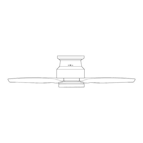
FAIRWIND HUGGER
LED CEILING FAN
MODEL #FWH60BNK3LRS
Español p. 18
ATTACH YOUR RECEIPT HERE
APPROVED FOR USE IN
DAMP LOCATIONS
Purchase Date
Questions, problems, missing parts? Before returning to your retailer, call our customer
service department at
1-800-527-1292, 8:30 a.m. - 5 p.m., CST, Monday - Friday.
1
Advertisement
Table of Contents

Related Manuals for Harbor Breeze FWH60BNK3LRS


Summary of Contents for Harbor Breeze FWH60BNK3LRS
- Page 1 ITEM #1596996 FAIRWIND HUGGER LED CEILING FAN MODEL #FWH60BNK3LRS Español p. 18 ATTACH YOUR RECEIPT HERE APPROVED FOR USE IN DAMP LOCATIONS Purchase Date Questions, problems, missing parts? Before returning to your retailer, call our customer service department at 1-800-527-1292, 8:30 a.m. - 5 p.m., CST, Monday - Friday.
-
Page 2: Table Of Contents
TABLE OF CONTENTS Safety Information ........................2 Package Contents ........................4 Hardware Contents ...........................5 Preparation ...........................5 Initial Installation ........................5 Wiring ............................7 Final Installation ........................9 Operating Instructions .......................13 Care and Maintenance ......................16 Troubleshooting........................16 Limited Lifetime Warranty ....................17 Replacement Parts List .......................17 SAFETY INFORMATION READ AND SAVE THESE INSTRUCTIONS •... - Page 3 SAFETY INFORMATION WARNING WARNING To reduce the risk of fire, electrical shock or personal injury, mount fan to outlet box marked "ACCEPTABLE FOR FAN SUPPORT OF 35 LBS. OR LESS" and use mounting screws provided with the outlet box. Most outlet boxes commonly used for the support of lighting fixtures are not acceptable for fan support and may need to be replaced.
-
Page 4: Package Contents
PACKAGE CONTENTS PART DESCRIPTION PART DESCRIPTION QUANTITY QUANTITY LED Light Kit Mounting Plate Mounting Plate Screw/Washer Shade (preassembled) Blade Ring Blade Plate Motor Housing Fitter Plate Screw (preassembled) Motor Plate Screw (preassembled) Remote Pack Fitter Plate Remote Control Receiver IMPORTANT REMINDER: You must use the parts provided with this fan for proper installation and safety. -
Page 5: Hardware Contents
HARDWARE CONTENTS (shown actual size) Motor Wire Screw/Washer Connector Qty. 6 Qty. 3 + 1 extra + 1 extra PREPARATION Before beginning assembly of product, make sure all parts are present. Place motor on carpet or on foam to avoid damage to finish. Compare parts with package contents list and hardware contents list. If any part is missing or damaged, do not attempt to install, operate or assemble the product. - Page 6 INITIAL INSTALLATION This fan can be mounted as a flushmount on a regular (no-slope) ceiling only. 30 in. Check to make sure blades (I) will be at least min. 30 inches from any obstruction and at least 7 ft. above the floor. 7 ft.
-
Page 7: Wiring
INITIAL INSTALLATION With wider opening facing up, place ring (C) over top of motor housing (D). Allow ring (C) to rest on top of motor, proceed to step 6. Lift motor housing (D) to mounting plate (A). Hang motor housing (D) on J-hook on underside of mounting plate (A). - Page 8 WIRING Make the necessary wiring connections for GROUND (GREEN OR BARE) WHITE SUPPLY WIRE remote control operation as detailed below and GROUND in the figure. For each wire connection, use one (GREEN OR BARE) BLACK SUPPLY WIRE of the wire connectors (AA), (L), making sure to screw wire connector on in a clockwise direction.
-
Page 9: Final Installation
FINAL INSTALLATION Remove motor housing (D) from J-hook. Gently slide remote control receiver (M) flat-side up into top of Antenna motor housing (D), pushing wires, wire connectors and antenna within. NOTE: The remote control included with this fan meets the following requirements: a. - Page 10 FINAL INSTALLATION CAUTION: To reduce the risk of serious bodily injury, DO NOT use power tools to assemble the blades (I). If overtightened, blades (I) may crack and break. Place one blade plate (J) under blade (I), aligning holes. Then, insert one motor screw/washer (BB) into one of the holes at the end of the blade (I), turning until the motor screw/washer (BB) comes through the other side of the blade (I).
- Page 11 FINAL INSTALLATION 6. Partially loosen two fitter plate screws (K) on the underside of the fitter plate (F) and remove the other fitter plate screw (K). 7. Connect WHITE wire from LED light kit (G) to WHITE wire from motor housing (D). Connect BLUE wire from LED light kit (G) to BLUE or (BLACK) wire from motor housing (D).
- Page 12 FINAL INSTALLATION 9. Align slots on shade (H) with protrusions on underside of fitter plate (F). Turn shade (H) clockwise until it no longer turns. NOTE: Pull down gently on shade (H) to make sure it is secured completely. Protrusion Slot 10.
-
Page 13: Operating Instructions
OPERATING INSTRUCTIONS CAUTION: The remote control transmitter can be programmed to multiple receivers or fans. If this is not desired, turn wall switch off to any other programmable receiver or fan. FCC Compliance Notice for Remote Control Modifications not approved by the party responsible for compliance could void the user's authority to operate the equipment. - Page 14 OPERATING INSTRUCTIONS 2. Restore electrical power. Within 30 seconds of restoring electrical power, press and hold the “0” button on the remote control transmitter for 5 seconds or until light on the fan blinks twice. Use the remote control transmitter to test the light and fan functions to confirm the learning process is complete.
- Page 15 OPERATING INSTRUCTIONS 4. Use the fan reverse switch, located on the motor housing (D), to optimize the fan for seasonal performance. A ceiling fan will allow you to raise your thermostat setting in summer and lower your thermostat setting in winter without feeling a difference in your comfort.
-
Page 16: Care And Maintenance
CARE AND MAINTENANCE At least twice each year, check mounting plate screws (E) and then tighten all screws on the fan. Clean motor housing (D) with only a soft brush or lint-free cloth to avoid scratching the finish. Clean blades (I) with a lint-free cloth. IMPORTANT: Shut off main power supply before beginning any maintenance. -
Page 17: Limited Lifetime Warranty
LIMITED LIFETIME WARRANTY The distributor warrants this fan to be free from defects in workmanship and materials present at time of shipment from the factory for Lifetime limited from the date of purchase. This warranty applies only to the original purchaser. The distributor agrees to correct any defect at no charge or, at our option, replace the ceiling fan with a comparable or superior model.
Need help?
Do you have a question about the FWH60BNK3LRS and is the answer not in the manual?
Questions and answers