Table of Contents
Advertisement
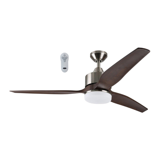
ITEM #1145467
1145466
FAIRWIND CEILING FAN
MODEL #FW60BNK3LRS
FW60LW3LRS
Español p. 19
ATTACH YOUR RECEIPT HERE
APPROVED FOR USE IN
DAMP LOCATIONS
Serial Number
Purchase Date
Questions, problems, missing parts? Before returning to your retailer, call our customer
service department at
1-800-527-1292, 8:30 a.m. - 5 p.m., CST, Monday - Friday.
1
Advertisement
Table of Contents

Related Manuals for Harbor Breeze FAIRWIND


Summary of Contents for Harbor Breeze FAIRWIND
- Page 1 ITEM #1145467 1145466 FAIRWIND CEILING FAN MODEL #FW60BNK3LRS FW60LW3LRS Español p. 19 ATTACH YOUR RECEIPT HERE APPROVED FOR USE IN DAMP LOCATIONS Serial Number Purchase Date Questions, problems, missing parts? Before returning to your retailer, call our customer service department at...
-
Page 2: Table Of Contents
TABLE OF CONTENTS Safety Information ........................2 Package Contents ........................4 Hardware Contents ...........................5 Preparation ...........................5 Initial Installation ........................6 Wiring ............................9 Final Installation ........................11 Operating Instructions .......................14 Care and Maintenance ......................16 Troubleshooting........................17 Limited Lifetime Warranty ....................18 Replacement Parts List .......................18 SAFETY INFORMATION READ AND SAVE THESE INSTRUCTIONS Please read and understand this entire manual before attempting to assemble, install or operate the product. - Page 3 SAFETY INFORMATION WARNING WARNING To reduce the risk of fire, electrical shock or personal injury, mount fan to outlet box marked "ACCEPTABLE FOR FAN SUPPORT OF 35 LBS. OR LESS" and use mounting screws provided with the outlet box. Most outlet boxes commonly used for the support of lighting fixtures are not acceptable for fan support and may need to be replaced.
-
Page 4: Package Contents
PACKAGE CONTENTS PART DESCRIPTION PART DESCRIPTION QUANTITY QUANTITY Downrod Canopy Mounting Screw (preassembled) Canopy Pin (preassembled) Mounting Bracket Clip (preassembled) Motor Housing Fitter Plate Yoke Cover Motor Plate Screw Light Kit Fitter (preassembled) Blade Fitter Plate Screw Canopy Cover (preassembled) Glass Shade Remote Pack Blade Plate... -
Page 5: Hardware Contents
HARDWARE CONTENTS (shown actual size) Motor Wire Screw/Washer Connector Qty. 7 Qty. 9 PREPARATION Before beginning assembly of product, make sure all parts are present. Place motor on carpet or on foam to avoid damage to finish. Compare parts with package contents list and hardware contents list. If any part is missing or damaged, do not attempt to install, operate or assemble the product. -
Page 6: Initial Installation
INITIAL INSTALLATION Turn off circuit breakers or fuse and wall switch to the fan supply line leads. DANGER: Failure to disconnect power supply prior to installation may result in serious injury or death. 2. Determine mounting method to use. A. Standard mount B. - Page 7 INITIAL INSTALLATION Secure mounting bracket (C) to outlet box (not STANDARD MOUNT ANGLE MOUNT included) using screws, spring washers and flat washers provided with the outlet box. *NOTE: It is very important you use the proper hardware when installing the mounting bracket (C) as this will support the fan.
- Page 8 INITIAL INSTALLATION 7. Slip downrod (A) into motor housing yoke, align holes and re-install pin (L) and clip (M). Tighten set screws in motor housing yoke and then tighten preassembled nuts on the set screws. Then, slide yoke cover (E) down until it rests on top of motor housing (D).
-
Page 9: Wiring
INITIAL INSTALLATION Install hanging ball of downrod (A) into opening of mounting bracket (C). Align one of the slots in hanging ball with tab in mounting bracket (C). DANGER: Failure to align one of the slots in the ball with the tab may result in serious injury or death. - Page 10 WIRING (1.) Connect all GROUND (GREEN) wires from fan (on GROUND (GREEN OR BARE) WHITE SUPPLY WIRE downrod (A), if applicable, and mounting bracket (C)) to GROUND BARE/GREEN supply wire from ceiling. (GREEN OR BARE) BLACK SUPPLY WIRE Connect BLACK wire (labeled AC IN L) from remote BLUE WHITE WHITE...
-
Page 11: Final Installation
FINAL INSTALLATION Locate two canopy mounting screws (K) on underside of mounting bracket (C) and remove canopy mounting screw (K) closest to the open end of the mounting bracket (C). Partially loosen the other canopy mounting screw (K). Lift canopy (B) to mounting bracket (C). - Page 12 FINAL INSTALLATION 3. Partially loosen two motor plate screws (O) in motor plate on underside of motor housing (D) and remove the other motor plate screw (O). Align slotted holes in fitter plate (N) with loosened motor plate screws (O), allowing molex connections from Motor motor housing (D) to come through hole in fitter Plate...
- Page 13 FINAL INSTALLATION 6. Carefully arrange wiring within the fitter plate (N) to ensure wires do not get pinched when attaching the light kit fitter (F). Align slotted holes in light kit fitter (F) with loosened fitter plate screws (P) on fitter plate (N). Twist light kit fitter (F) to lock in place.
-
Page 14: Operating Instructions
OPERATING INSTRUCTIONS CAUTION: The remote control transmitter can be programmed to multiple receivers or fans. If this is not desired, turn wall switch off to any other programmable receiver or fan. FCC Compliance Notice for Remote Control Modifications not approved by the party responsible for compliance could void the user's authority to operate the equipment. - Page 15 OPERATING INSTRUCTIONS 2. Restore electrical power. Within 30 seconds of restoring electrical power, press and hold the “0” button on the remote control transmitter for 5 seconds or until light on the fan blinks twice. Use the remote control transmitter to test the light and fan functions to confirm the learning process is complete.
-
Page 16: Care And Maintenance
OPERATING INSTRUCTIONS 4a. In warmer weather, setting the reverse switch in the LEFT position will result in downward airflow creating a wind chill effect. 4b. In cooler weather, setting the reverse switch in the RIGHT position will result in upward airflow that can help move stagnant, hot air off the ceiling area. -
Page 17: Troubleshooting
TROUBLESHOOTING WARNING: Before beginning work, shut off the power supply to avoid electrical shock. PROBLEM POSSIBLE CAUSE CORRECTIVE ACTION Fan does not 1. Reverse switch not engaged. 1. Push switch firmly either up or move. down. 2. Power is off or fuse is blown. 2. -
Page 18: Limited Lifetime Warranty
LIMITED LIFETIME WARRANTY The distributor warrants this fan to be free from defects in workmanship and materials present at time of shipment from the factory for Lifetime limited from the date of purchase. This warranty applies only to the original purchaser. The distributor agrees to correct any defect at no charge or, at our option, replace the ceiling fan with a comparable or superior model.
Need help?
Do you have a question about the FAIRWIND and is the answer not in the manual?
Questions and answers
**** turns on when I flip the wall switch. But when I try to use the remote it doesn’t respond. The indicator light on the remote flickers so I assume that means the battery works fine.
The Harbor Breeze FAIRWIND ceiling fan may not be responding to the remote control due to the following reasons:
1. Incorrect Remote Compatibility – The fan's remote control must meet the required electrical rating (120V / 60 Hz, motor amps: 1.25 MAX). If a different remote is used, it must also meet these specifications.
2. Improper Installation of Remote Receiver – The remote control receiver must be installed correctly, with the antenna hanging to the side.
3. Loose or Improper Wiring Connections – Ensure all wire connections are secure and covered with tape to prevent exposed wires.
4. Battery Issues – The remote control batteries may be depleted or improperly installed.
5. Interference or Signal Blockage – Objects or other electronic devices could be interfering with the remote signal.
To resolve the issue, check the wiring, ensure the correct remote is used, replace the batteries, and verify that there is no interference.
This answer is automatically generated
@Mr. Anderson Remote is the original that came with the ****. It worked for the first 3 years. It all of sudden stopped working. Like I said in my original post, battery light indicator is blinking when button is pressed so that tells me that remote is getting power. I checked wiring and everything appears fine and has worked fine for 3 years. Seems early for transmitter to not be working. **** is only 3 years old