
Related Manuals for LEYBOLD TURBO.CONTROL i


Summary of Contents for LEYBOLD TURBO.CONTROL i
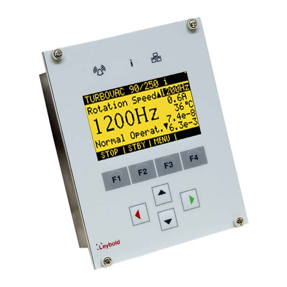
- Page 1 TURBOVAC i/iX TURBO.CONTROL i 24 VDC Display Unit Brief Instructions 300680364_002_C0 Part No. 800100V0004...
- Page 2 Instructions and follow the information so as to ensure optimum and safe working right from the start. The Leybold Display Unit has been designed for safe and efficient operation when used properly and in accordance with these Operating Instructions. It is the responsibility of...
-
Page 3: Important Safety Information
Make the electrical connections only after pump and accessories (e.g. air cooler) have been installed mechanically. 300680364_002_C0 - 12/2017 - © Leybold... -
Page 4: Technical Data
Tool DataViewer. The TURBO.CONTROL i contains a battery (button cell) for data buffering. The TURBO.CONTROL i can be installed in a rack or be mounted in a table housing provided for it. The table hous- ing is available as an accessory. - Page 5 Description 300680364_002_C0 - 12/2017 - © Leybold...
- Page 6 (Software updating, data logging etc.). Max. cable length 30 m Gauge 1 / At the TURBO.CONTROL i two vacuum Gauge 2 gauge heads can be connected. For this, two of the following types can be used: PTR 90, PTR 90N, TTR 91, TTR 91N, TTR101, TTR 101N.
-
Page 7: Conforming Use
Busterminierung Fig. 2 Pin assignment RS 485 Conforming Use The TURBO.CONTROL i is intended for operating the following turbomolecular pumps: TURBOVAC 90 i(X), 250 i(X), (T) 350 i(X), (T) 450 i(X) Part Nos.: 810030V1000 to 810089V9999... -
Page 8: Operation
Operation Operation Switching On The display starts by applying the 24 VDC supply voltage. The communication between TURBO.CONTROL i and a turbo molecular pump can be established via RS485 or USB. TURBO.CONTROL i automatically detects the pump and loads the appropriate setting. This process may take a few seconds. - Page 9 All the values previously changed are saved by confirming the query. The saving procedure may take a few seconds. The ■ pump must not be separated from the supply voltage during the saving procedure. 300680364_002_C0 - 12/2017 - © Leybold...
-
Page 10: Changing The Battery
When the battery is missing or empty, no real time clock can be saved in the Data Logging. The function of the the TURBO.CONTROL i is not affected. Disconnect the device from voltage. Remove the rubber cover on the rear side to replace the battery Use only the intended battery type CR1/3N. -
Page 11: Waste Disposal
Separate clean components according to their materials, and dispose of these accordingly. We offer this service. Further details are available on request. When sending us any equipment, observe the regulations given in Section “Leybold Service”. 300680364_002_C0 - 12/2017 - © Leybold... -
Page 12: Eu Declaration Of Conformity
+1-724-325-3577 Sales: info.ex@leybold.com Malaysia +44-13-7273 7300 Sales: +44-13-7273 7301 +1-724-327-5700 Leybold Malaysia sales.ln@leybold.com +1-724-333-1217 Leybold Singapore Pte Ltd. Service: Service: No. 1 Jalan Hi-Tech 2/6 +44-13-7273 7320 +1-724-327-5700 Kulim Hi-Tech Park +44-13-7273 7303 +1-724-325-3577 Kulim, Kedah Darul service.ln@leybold.com 5 609 0...
Need help?
Do you have a question about the TURBO.CONTROL i and is the answer not in the manual?
Questions and answers